Seat - Dtc/circuit Diagnosis
- B2490-13 Front Seat Heater Lh
- B2490-19 Front Seat Heater Lh
- B2495-13 Rear Seat Heater Lh
- B2495-19 Rear Seat Heater Lh
- U1ca3-08 Seat Heater Communication
- U1ca7-02 Front Seat Heater Lh Communication
- U1ca9-02 Rear Seat Heater Lh Communication
- Front Seat Heater Lh
- Second Row Seat Heater Lh
- Seat Blower Lh
- Walk in Switch
- Seat Angle Sensor
- Seat Walk in Motor
- Power Supply and Ground Circuit. Second Row Seat Power Walk in Control Unit
B2490-13 Front Seat Heater Lh Nissan Pathfinder 2022
DTC Description
DTC DETECTION LOGIC
| DTC No. | CONSULT screen items (Trouble diagnosis content) | DTC detection condition | |
|---|---|---|---|
| B2490-13 | FRONT SEAT HEATER LH (Front seat heater left hand) |
Diagnosis condition | Engine running |
| Signal (terminal) | — | ||
| Threshold | CPU in front seat heater LH detect heating wire resistance more than 2.6 Ω | ||
| Diagnosis delay time | 1.5 seconds or more | ||
POSSIBLE CAUSE
Harness or connectors (front seat heater LH ground circuit is open)
Seat cushion heater LH
Seat back heater LH
FAIL-SAFE
—
DTC CONFIRMATION PROCEDURE
PERFORM DTC CONFIRMATION PROCEDURE
 CONSULT
Start the engine.
Select “Self Diagnostic Result” mode of “HVAC”.
Is DTC detected?
YES>>Refer to DTC Diagnosis Procedure.
NO>>To check malfunction symptom before repair: Refer to Intermittent Incident.
NO>>Confirmation after repair: Inspection End.
DTC Diagnosis Procedure
CHECK FRONT SEAT HEATER LH GROUND CIRCUIT (OPEN)
Ignition switch OFF.
Disconnect front seat heater LH connector.
Check continuity between front seat heater LH harness connector and ground.
With heated seat Front seat heater LH — Continuity Connector Terminal B230 4 Ground Yes With climate controlled seat Front seat heater LH — Continuity Connector Terminal B232 1 Ground Yes 5
Is the inspection result normal?
YES>>GO TO 2.
NO>>Repair the harness or connector.
CHECK SEAT BACK HEATER LH CIRCUIT (OPEN)
Disconnect front seat back heater LH connector.
Check continuity between front seat back heater LH harness connector and front seat heater LH harness connector.
With heated seat Front seat back heater LH Front seat heater LH Continuity Connector Terminal Connector Terminal B235 2 B231 1 Yes With climate controlled seat Front seat back heater LH Front seat heater LH Continuity Connector Terminal Connector Terminal B237 2 B236 2 Yes
Is the inspection result normal?
YES>>GO TO 3.
NO>>Replace seat cushion heater LH. Refer to Seat Cushion.
CHECK SEAT BACK HEATER LH GROUND CIRCUIT (OPEN)
Check continuity between front seat back heater LH harness connector and front seat heater LH harness connector.
| Front seat back heater LH | Front seat heater LH | Continuity | ||
|---|---|---|---|---|
| Connector | Terminal | Connector | Terminal | |
| B235 | 1 | B231 | 4 | Yes |
| Front seat back heater LH | Front seat heater LH | Continuity | ||
|---|---|---|---|---|
| Connector | Terminal | Connector | Terminal | |
| B237 | 1 | B236 | 5 | Yes |
Is the inspection result normal?
YES>>Replace front seat back heater LH. Refer to Seat Back.
NO>>Replace seat cushion heater LH. Refer to Seat Cushion.
B2490-19 Front Seat Heater Lh Nissan Pathfinder 5th Gen
DTC Description
DTC DETECTION LOGIC
| DTC No. | CONSULT screen items (Trouble diagnosis content) | DTC detection condition | |
|---|---|---|---|
| B2490-19 | FRONT SEAT HEATER LH (Front seat heater left hand) |
Diagnosis condition | Engine running |
| Signal (terminal) | — | ||
| Threshold | CPU in front seat heater LH detect heating wire resistance less than 1.3 Ω | ||
| Diagnosis delay time | 1.5 seconds or more | ||
POSSIBLE CAUSE
Seat cushion heater LH
Front seat back heater LH
FAIL-SAFE
—
DTC CONFIRMATION PROCEDURE
PERFORM DTC CONFIRMATION PROCEDURE
 CONSULT
Start the engine.
Select “Self Diagnostic Result” mode of “HVAC”.
Is DTC detected?
YES>>Refer to DTC Diagnosis Procedure.
NO>>To check malfunction symptom before repair: Refer to Intermittent Incident.
NO>>Confirmation after repair: Inspection End.
DTC Diagnosis Procedure
CHECK FRONT SEAT BACK HEATER LH CIRCUIT (SHORT TO GROUND)
Ignition switch OFF.
Disconnect front seat heater LH connector and front seat back heater LH connector.
Check continuity between front seat back heater LH harness connector and ground.
With heated seat Front seat back heater LH — Continuity Connector Terminal B235 2 Ground No With climate controlled seat Front seat back heater LH — Continuity Connector Terminal B237 2 Ground No
Is the inspection result normal?
YES>>Replace front seat back heater LH. Refer to Seat Back.
NO>>Replace seat cushion heater LH. Refer to Seat Cushion.
B2495-13 Rear Seat Heater Lh Nissan Pathfinder 2022
DTC Description
DTC DETECTION LOGIC
| DTC No. | CONSULT screen items (Trouble diagnosis content) | DTC detection condition | |
|---|---|---|---|
| B2495-13 | REAR SEAT HEATER LH (Rear seat heater left hand) |
Diagnosis condition | Engine running |
| Signal (terminal) | — | ||
| Threshold | CPU in second row seat heater LH detect heating wire resistance more than 2.6 Ω | ||
| Diagnosis delay time | 1.5 seconds or more | ||
POSSIBLE CAUSE
Harness or connectors
Second row seat cushion heater LH
Second row seat back heater LH
FAIL-SAFE
—
DTC CONFIRMATION PROCEDURE
PERFORM DTC CONFIRMATION PROCEDURE
 CONSULT
Start the engine.
Select “Self Diagnostic Result” mode of “HVAC”.
Is DTC detected?
YES>>Refer to DTC Diagnosis Procedure.
NO>>To check malfunction symptom before repair: Refer to Intermittent Incident.
NO>>Confirmation after repair: Inspection End.
DTC Diagnosis Procedure
CHECK SECOND ROW SEAT CUSHION HEATER LH GROUND CIRCUIT (OPEN)
Ignition switch OFF.
Disconnect second row seat cushion heater LH connector.
Check continuity between second row seat cushion heater LH harness connector and ground.
Second row seat cushion heater LH — Continuity Connector Terminal B547 4 Ground Yes
Is the inspection result normal?
YES>>GO TO 2.
NO>>Repair the harness or connector.
CHECK SECOND ROW SEAT BACK HEATER LH CIRCUIT (OPEN)
Disconnect second row seat back heater LH connector.
Check continuity between second row seat back heater LH harness connector and second row seat cushion heater LH harness connector.
| Second row seat back heater LH | Second row seat cushion heater LH | Continuity | ||
|---|---|---|---|---|
| Connector | Terminal | Connector | Terminal | |
| B526 | 2 | B547 | 3 | Yes |
Is the inspection result normal?
YES>>GO TO 3.
NO>>Repair the harness or connector.
CHECK SECOND ROW SEAT BACK HEATER LH GROUND CIRCUIT (OPEN)
Check continuity between second row seat back heater LH harness connector and ground.
| Second row seat back heater LH | — | Continuity | |
|---|---|---|---|
| Connector | Terminal | ||
| B526 | 1 | Ground | Yes |
Is the inspection result normal?
YES>>Replace second row seat cushion heater LH. Refer to Removal and Installation.
NO>>Repair the harness or connector.
B2495-19 Rear Seat Heater Lh Nissan Pathfinder
DTC Description
DTC DETECTION LOGIC
| DTC No. | CONSULT screen items (Trouble diagnosis content) | DTC detection condition | |
|---|---|---|---|
| B2495-19 | REAR SEAT HEATER LH (Rear seat heater left hand) |
Diagnosis condition | Engine running |
| Signal (terminal) | — | ||
| Threshold | CPU in second row seat heater LH detect heating wire resistance less than 1.3 Ω | ||
| Diagnosis delay time | 1.5 seconds or more | ||
POSSIBLE CAUSE
Second row seat cushion heater LH
Second row seat back heater LH
FAIL-SAFE
—
DTC CONFIRMATION PROCEDURE
PERFORM DTC CONFIRMATION PROCEDURE
 CONSULT
Start the engine.
Select “Self Diagnostic Result” mode of “HVAC”.
Is DTC detected?
YES>>Refer to DTC Diagnosis Procedure.
NO>>To check malfunction symptom before repair: Refer to Intermittent Incident.
NO>>Confirmation after repair: Inspection End.
DTC Diagnosis Procedure
CHECK SECOND ROW SEAT BACK HEATER LH CIRCUIT (SHORT TO GROUND)
Ignition switch OFF.
Disconnect second row seat cushion heater LH connector and second row seat back heater LH connector.
Check continuity between second row seat back heater LH harness connector and ground.
Second row seat back heater LH — Continuity Connector Terminal B256 2 Ground No
Is the inspection result normal?
YES>>Replace second row seat back heater LH. Refer to Removal and Installation.
NO>>Repair the harness or connector.
U1ca3-08 Seat Heater Communication Nissan Pathfinder 2022
DTC Description
DTC DETECTION LOGIC
| DTC No. | CONSULT screen items (Trouble diagnosis content) | DTC detection condition | |
|---|---|---|---|
| U1CA3-08 | SEAT HEATER COMMUNICATION (Seat heater communication) |
Diagnosis condition | Engine running |
| Signal (terminal) | LIN (heated seat) signal (terminal #45) | ||
| Threshold | A/C auto amp. is not transmitting or receiving LIN communication with each seat heater | ||
| Diagnosis delay time | 2 seconds or more | ||
POSSIBLE CAUSE
Fuse
Harness or connectors (seat heater circuit is open or short to ground)
Each seat cushion heater
A/C auto amp.
FAIL-SAFE
—
DTC CONFIRMATION PROCEDURE
PERFORM DTC CONFIRMATION PROCEDURE
 CONSULT
Start the engine.
Select “Self Diagnostic Result” mode of “HVAC”.
Is DTC detected?
YES>>Refer to DTC Diagnosis Procedure.
NO>>To check malfunction symptom before repair: Refer to Intermittent Incident.
NO>>Confirmation after repair: Inspection End.
DTC Diagnosis Procedure
CHECK DTC
 CONSULT
Start the engine.
Select “Self Diagnostic Result” mode of “HVAC”.
Check following DTC:
DTC Items
(CONSULT screen terms)Reference U1CA6-02 FRONT SEAT HEATER RH COMMUNICATION DTC Description U1CA7-02 FRONT SEAT HEATER LH COMMUNICATION DTC Description U1CA8-02 REAR SEAT HEATER RH COMMUNICATION DTC Description U1CA9-02 REAR SEAT HEATER LH COMMUNICATION DTC Description
Is DTC detected?
YES>>Perform diagnosis procedure for the DTC that is detected.
NO>>Replace A/C auto amp. Refer to Removal and Installation.
U1ca7-02 Front Seat Heater Lh Communication Nissan Pathfinder R53
DTC Description
DTC DETECTION LOGIC
| DTC No. | CONSULT screen items (Trouble diagnosis content) | DTC detection condition | |
|---|---|---|---|
| U1CA7-02 | FRONT SEAT HEATER LH COMMUNICATION (Front seat heater left hand communication) |
Diagnosis condition | Engine running |
| Signal (terminal) | LIN (heated seat) signal (terminal #45) | ||
| Threshold | A/C auto amp. is not transmitting or receiving LIN communication with front seat heater LH | ||
| Diagnosis delay time | 2 seconds or more | ||
POSSIBLE CAUSE
Fuse
Harness or connectors (front seat heater LH circuit is open or short to ground)
Front seat cushion heater LH
A/C auto amp.
FAIL-SAFE
—
DTC CONFIRMATION PROCEDURE
PERFORM DTC CONFIRMATION PROCEDURE
 CONSULT
Start the engine.
Select “Self Diagnostic Result” mode of “HVAC”.
Is DTC detected?
YES>>Refer to DTC Diagnosis Procedure.
NO>>To check malfunction symptom before repair: Refer to Intermittent Incident.
NO>>Confirmation after repair: Inspection End.
DTC Diagnosis Procedure
CHECK FUSE
Ignition switch OFF.
Check that the following fuse is not blown (open):
Signal name Fuse No. Capacity Front seat heater LH power supply 66 30A
Is the fuse blown (open)?
YES>>Replace the blown (open) fuse after repairing the affected circuit if a fuse is blown (open).
NO>>GO TO 2.
CHECK FRONT SEAT HEATER LH POWER SUPPLY VOLTAGE
Disconnect front seat heater LH connector.
Start the engine.
Check voltage between front seat heater LH harness connector and ground.
With heated seat + - Voltage
(Approx.)Front seat heater LH Connector Terminal B230 1 Ground Battery voltage With climate controlled seat + - Voltage
(Approx.)Front seat heater LH Connector Terminal B232 2 Ground Battery voltage
Is the inspection result normal?
YES>>GO TO 3.
NO>>Repair the harness or connector.
CHECK FRONT SEAT HEATER LH GROUND CIRCUIT (OPEN)
Ignition switch OFF.
Check continuity between front seat heater LH harness connector and ground.
With heated seat Front seat heater LH — Continuity Connector Terminal B230 4 Ground Yes With climate controlled seat Front seat heater LH — Continuity Connector Terminal B232 1 Ground Yes 5
Is the inspection result normal?
YES>>GO TO 4.
NO>>Repair the harness or connector.
CHECK FRONT SEAT HEATER LH LIN SIGNAL
Ignition switch ON.
Confirm output waveform between front seat heater LH harness connector and ground with oscilloscope.
With heated seat + - Output waveform Front seat heater RH Connector Terminal B230 2 Ground 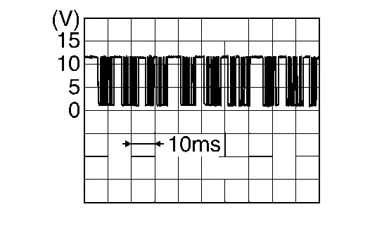
With climate controlled seat + - Output waveform Front seat heater RH Connector Terminal B232 6 Ground 
Is the inspection result normal?
YES>>Replace seat cushion heater LH. Refer to Seat Cushion.
NO>>GO TO 5.
CHECK FRONT SEAT HEATER LH LIN SIGNAL CIRCUIT (OPEN)
Ignition switch OFF.
Disconnect A/C auto amp. connector.
Check continuity between front seat heater LH harness connector and A/C auto amp. harness connector.
With heated seat Front seat heater LH A/C auto amp. Continuity Connector Terminal Connector Terminal B230 2 M60 45 Yes With climate controlled seat Front seat heater LH A/C auto amp. Continuity Connector Terminal Connector Terminal B232 6 M60 45 Yes
Is the inspection result normal?
YES>>GO TO 6.
NO>>Repair the harness or connector.
CHECK FRONT SEAT HEATER LH LIN SIGNAL CIRCUIT (SHORT TO GROUND)
Disconnect the following connectors:
Front seat heater RH
Second row seat cushion heater LH
Second row seat cushion heater RH
Check continuity between front seat heater LH harness connector and ground.
With heated seat Front seat heater LH — Continuity Connector Terminal B230 2 Ground No With climate controlled seat Front seat heater LH — Continuity Connector Terminal B232 6 Ground No
Is the inspection result normal?
YES>>Replace A/C auto amp. Refer to Removal and Installation.
NO>>Repair the harness or connector.
U1ca9-02 Rear Seat Heater Lh Communication Nissan Pathfinder R53
DTC Description
DTC DETECTION LOGIC
| DTC No. | CONSULT screen items (Trouble diagnosis content) | DTC detection condition | |
|---|---|---|---|
| U1CA9-02 | REAR SEAT HEATER LH COMMUNICATION (Rear seat heater left hand communication) |
Diagnosis condition | Engine running |
| Signal (terminal) | LIN (heated seat) signal (terminal #45) | ||
| Threshold | A/C auto amp. is not transmitting or receiving LIN communication with second row seat cushion heater LH | ||
| Diagnosis delay time | 2 seconds or more | ||
POSSIBLE CAUSE
Fuse
Harness or connectors (second row seat cushion heater LH circuit is open or short to ground)
Second row seat cushion heater LH
A/C auto amp.
FAIL-SAFE
—
DTC CONFIRMATION PROCEDURE
PERFORM DTC CONFIRMATION PROCEDURE
 CONSULT
Start the engine.
Select “Self Diagnostic Result” mode of “HVAC”.
Is DTC detected?
YES>>Refer to DTC Diagnosis Procedure.
NO>>To check malfunction symptom before repair: Refer to Intermittent Incident.
NO>>Confirmation after repair: Inspection End.
DTC Diagnosis Procedure
CHECK FUSE
Ignition switch OFF.
Check that the following fuse is not blown (open):
Signal name Fuse No. Capacity Second row seat cushion heater LH power supply 66 30A
Is the fuse blown (open)?
YES>>Replace the blown (open) fuse after repairing the affected circuit if a fuse is blown (open).
NO>>GO TO 2.
CHECK SECOND ROW SEAT CUSHION HEATER LH POWER SUPPLY VOLTAGE
Disconnect second row seat cushion heater LH connector.
Start the engine.
Check voltage between second row seat cushion heater LH harness connector and ground.
+ - Voltage
(Approx.)Second row seat cushion heater LH Connector Terminal B547 1 Ground Battery voltage
Is the inspection result normal?
YES>>GO TO 3.
NO>>Repair the harness or connector.
CHECK SECOND ROW SEAT CUSHION HEATER LH GROUND CIRCUIT (OPEN)
Ignition switch OFF.
Check continuity between second row seat cushion heater LH harness connector and ground.
Second row seat cushion heater LH — Continuity Connector Terminal B547 4 Ground Yes
Is the inspection result normal?
YES>>GO TO 4.
NO>>Repair the harness or connector.
CHECK SECOND ROW SEAT CUSHION HEATER LH LIN SIGNAL
Ignition switch ON.
Confirm output waveform between second row seat cushion heater LH harness connector and ground with oscilloscope.
+ - Output waveform Second row seat cushion heater LH Connector Terminal B547 2 Ground 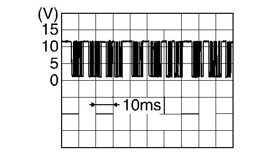
Is the inspection result normal?
YES>>Replace second row seat cushion heater LH. Refer to Removal and Installation.
NO>>GO TO 5.
CHECK SECOND ROW SEAT CUSHION HEATER LH LIN SIGNAL CIRCUIT (OPEN)
Ignition switch OFF.
Disconnect A/C auto amp. connector.
Check continuity between second row seat cushion heater LH harness connector and A/C auto amp. harness connector.
Second row seat cushion heater LH A/C auto amp. Continuity Connector Terminal Connector Terminal B547 2 M60 45 Yes
Is the inspection result normal?
YES>>GO TO 6.
NO>>Repair the harness or connector.
CHECK SECOND ROW SEAT CUSHION HEATER LH LIN SIGNAL CIRCUIT (SHORT TO GROUND)
Disconnect the following connectors:
Front seat heater LH
Front seat heater RH
Second row seat cushion heater RH
Check continuity between second row seat cushion heater LH harness connector and ground.
Second row seat cushion heater LH — Continuity Connector Terminal B547 2 Ground No
Is the inspection result normal?
YES>>Replace A/C auto amp. Refer to Removal and Installation.
NO>>Repair the harness or connector.
Front Seat Heater Lh Nissan Pathfinder Fifth generation
Component Function Check
CHECK FRONT SEAT HEATER LH FUNCTION
Start the engine.
Check that seat cushion and seat back of front seat LH warms when operating the front heated seat switch LH.
Is the inspection result normal?
YES>>Front seat heater LH function is OK.
NO>>Refer to Diagnosis Procedure.
Diagnosis Procedure
CHECK FUSE
Ignition switch OFF.
Check that the following fuse is not blown (open):
Signal name Fuse No. Capacity Front seat heater LH power supply 66 30A
Is the fuse blown (open)?
YES>>Replace the blown (open) fuse after repairing the affected circuit if a fuse is blown (open).
NO>>GO TO 2.
CHECK FRONT SEAT HEATER LH POWER SUPPLY VOLTAGE
Disconnect front seat heater LH connector.
Start the engine.
Check voltage between front seat heater LH harness connector and ground.
With heated seat + - Voltage
(Approx.)Front seat heater LH Connector Terminal B230 1 Ground Battery voltage With climate controlled seat + - Voltage
(Approx.)Front seat heater LH Connector Terminal B232 2 Ground Battery voltage
Is the inspection result normal?
YES>>GO TO 3.
NO>>Repair the harness or connector.
CHECK FRONT SEAT HEATER LH GROUND CIRCUIT (OPEN)
Ignition switch OFF.
Check continuity between front seat heater LH harness connector and ground.
With heated seat Front seat heater LH — Continuity Connector Terminal B230 4 Ground Yes With climate controlled seat Front seat heater LH — Continuity Connector Terminal B232 1 Ground Yes 5
Is the inspection result normal?
YES>>GO TO 4.
NO>>Repair the harness or connector.
CHECK FRONT SEAT HEATER LH LIN SIGNAL
Ignition switch ON.
Confirm output waveform between front seat heater LH harness connector and ground with oscilloscope.
With heated seat + - Output waveform Front seat heater RH Connector Terminal B230 2 Ground 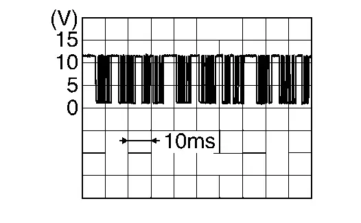
With climate controlled seat + - Output waveform Front seat heater RH Connector Terminal B232 6 Ground 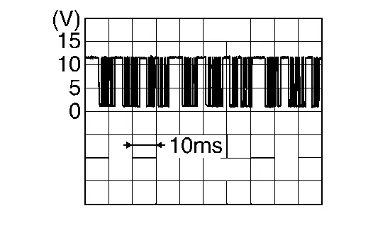
Is the inspection result normal?
YES>>GO TO 7.
NO>>GO TO 5.
CHECK FRONT SEAT HEATER LH LIN SIGNAL CIRCUIT (OPEN)
Ignition switch OFF.
Disconnect A/C auto amp. connector.
Check continuity between front seat heater LH harness connector and A/C auto amp. harness connector.
With heated seat Front seat heater LH A/C auto amp. Continuity Connector Terminal Connector Terminal B230 2 M60 45 Yes With climate controlled seat Front seat heater LH A/C auto amp. Continuity Connector Terminal Connector Terminal B232 6 M60 45 Yes
Is the inspection result normal?
YES>>GO TO 6.
NO>>Repair the harness or connector.
CHECK FRONT SEAT HEATER LH LIN SIGNAL CIRCUIT (SHORT TO GROUND)
Disconnect the following connectors:
Front seat heater RH
Second row seat cushion heater LH
Second row seat cushion heater RH
Check continuity between front seat heater LH harness connector and ground.
With heated seat Front seat heater LH — Continuity Connector Terminal B230 2 Ground No With climate controlled seat Front seat heater LH — Continuity Connector Terminal B232 6 Ground No
Is the inspection result normal?
YES>>Replace A/C auto amp. Refer to Removal and Installation.
NO>>Repair the harness or connector.
CHECK FRONT SEAT BACK HEATER LH CIRCUIT (OPEN)
Ignition switch OFF.
Disconnect front seat back heater LH connector.
Check continuity between front seat back heater LH harness connector and front seat heater LH harness connector.
With heated seat Front seat back heater LH Front seat heater LH Continuity Connector Terminal Connector Terminal B235 2 B231 1 Yes With climate controlled seat Front seat back heater LH Front seat heater LH Continuity Connector Terminal Connector Terminal B237 2 B236 2 Yes
Is the inspection result normal?
YES>>GO TO 8.
NO>>Replace seat cushion heater LH. Refer to Seat Cushion.
CHECK FRONT SEAT BACK HEATER LH GROUND CIRCUIT (OPEN)
Check continuity between front seat back heater LH harness connector and front seat heater LH harness connector.
| Front seat back heater LH | Front seat heater LH | Continuity | ||
|---|---|---|---|---|
| Connector | Terminal | Connector | Terminal | |
| B235 | 1 | B231 | 4 | Yes |
| Front seat back heater LH | Front seat heater LH | Continuity | ||
|---|---|---|---|---|
| Connector | Terminal | Connector | Terminal | |
| B237 | 1 | B236 | 5 | Yes |
Is the inspection result normal?
YES>>Replace front seat back heater LH. Refer to Seat Back.
NO>>Replace seat cushion heater LH. Refer to Seat Cushion.
Second Row Seat Heater Lh Nissan Pathfinder R53
Component Function Check
CHECK SECOND ROW SEAT HEATER LH FUNCTION
Start the engine.
Check that seat cushion and seat back of second row seat LH warms when operating the second row heated seat switch LH.
Is the inspection result normal?
YES>>Second row seat heater LH function is OK.
NO>>Refer to Diagnosis Procedure.
Diagnosis Procedure
CHECK FUSE
Ignition switch OFF.
Check that the following fuse is not blown (open):
Signal name Fuse No. Capacity Second row seat cushion heater LH power supply 66 30A
Is the fuse blown (open)?
YES>>Replace the blown (open) fuse after repairing the affected circuit if a fuse is blown (open).
NO>>GO TO 2.
CHECK SECOND ROW SEAT CUSHION HEATER LH POWER SUPPLY VOLTAGE
Disconnect second row seat cushion heater LH connector.
Start the engine.
Check voltage between second row seat cushion heater LH harness connector and ground.
+ - Voltage
(Approx.)Second row seat cushion heater LH Connector Terminal B547 1 Ground Battery voltage
Is the inspection result normal?
YES>>GO TO 3.
NO>>Repair the harness or connector.
CHECK SECOND ROW SEAT CUSHION HEATER LH GROUND CIRCUIT (OPEN)
Ignition switch OFF.
Check continuity between second row seat cushion heater LH harness connector and ground.
Second row seat cushion heater LH — Continuity Connector Terminal B547 4 Ground Yes
Is the inspection result normal?
YES>>GO TO 4.
NO>>Repair the harness or connector.
CHECK SECOND ROW SEAT CUSHION HEATER LH LIN SIGNAL
Ignition switch ON.
Confirm output waveform between second row seat cushion heater LH harness connector and ground with oscilloscope.
+ - Output waveform Second row seat cushion heater LH Connector Terminal B547 2 Ground 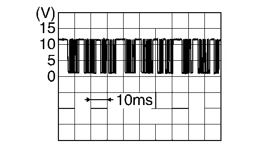
Is the inspection result normal?
YES>>GO TO 7.
NO>>GO TO 5.
CHECK SECOND ROW SEAT CUSHION HEATER LH LIN SIGNAL CIRCUIT (OPEN)
Ignition switch OFF.
Disconnect A/C auto amp. connector.
Check continuity between second row seat cushion heater LH harness connector and A/C auto amp. harness connector.
Second row seat cushion heater LH A/C auto amp. Continuity Connector Terminal Connector Terminal B547 2 M60 45 Yes
Is the inspection result normal?
YES>>GO TO 6.
NO>>Repair the harness or connector.
CHECK SECOND ROW SEAT CUSHION HEATER LH LIN SIGNAL CIRCUIT (SHORT TO GROUND)
Disconnect the following connectors:
Front seat heater LH
Front seat heater RH
Second row seat cushion heater RH
Check continuity between second row seat cushion heater LH harness connector and ground.
Second row seat cushion heater LH — Continuity Connector Terminal B547 2 Ground No
Is the inspection result normal?
YES>>Replace A/C auto amp. Refer to Removal and Installation.
NO>>Repair the harness or connector.
CHECK SECOND ROW SEAT BACK HEATER LH CIRCUIT (OPEN) 1
Ignition switch OFF
Disconnect second row seat back heater LH connector.
Check continuity between second row seat back heater LH harness connector and second row seat cushion heater LH harness connector.
Second row seat back heater LH Second row seat cushion heater LH Continuity Connector Terminal Connector Terminal B526 2 B547 3 Yes
Is the inspection result normal?
YES>>GO TO 8.
NO>>Repair the harness or connector.
CHECK SECOND ROW SEAT BACK HEATER LH CIRCUIT (OPEN) 2
Check continuity between second row seat cushion heater LH harness connector and second row seat cushion heater LH harness connector.
| Second row seat cushion heater LH | Continuity | |||
|---|---|---|---|---|
| Connector | Terminal | Connector | Terminal | |
| B548 | 3 | B548 | 1 | Yes |
Is the inspection result normal?
YES>>GO TO 9.
NO>>Replace second row seat cushion heater LH. Refer to Removal and Installation.
CHECK SECOND ROW SEAT BACK HEATER LH GROUND CIRCUIT (OPEN)
Check continuity between second row seat back heater LH harness connector and ground.
| Second row seat back heater LH | — | Continuity | |
|---|---|---|---|
| Connector | Terminal | ||
| B526 | 1 | Ground | Yes |
Is the inspection result normal?
YES>>Replace second row seat back heater LH. Refer to Removal and Installation.
NO>>Repair the harness or connector.
Seat Blower Lh Nissan Pathfinder
Component Function Check
CHECK FRONT SEAT HEATER LH FUNCTION
Start the engine.
Check that seat cushion heater and seat back heater of the front seat LH warms when operating the front heated seat switch LH.
Is the inspection result normal?
YES>>GO TO 2.
NO>>Refer to Diagnosis Procedure.
CHECK SEAT BLOWER LH FUNCTION
Start the engine.
Check that there is ventilation from the seat cushion blower and seat back blower when operating the climate controlled seat switch LH.
Is the inspection result normal?
YES>>Seat blower LH function is OK.
NO>>Refer to Diagnosis Procedure.
Diagnosis Procedure
CHECK FUSE
Ignition switch OFF.
Check that the following fuse is not blown (open):
Signal name Fuse No. Capacity Seat blower LH power supply 66 30A
Is the fuse blown (open)?
YES>>Replace the blown (open) fuse after repairing the affected circuit if a fuse is blown (open).
NO>>GO TO 2.
CHECK SEAT BLOWER LH POWER SUPPLY VOLTAGE
Disconnect seat cushion blower LH connector and seat back blower LH connector.
Start the engine.
Check voltage between seat cushion blower LH harness connector, seat back blower LH harness connector and ground.
Seat cushion blower + - Voltage
(Approx.)Seat cushion blower LH Connector Terminal B233 3 Ground Battery voltage Seat back blower + - Voltage
(Approx.)Seat back blower LH Connector Terminal B234 3 Ground Battery voltage
Is the inspection result normal?
YES>>GO TO 3.
NO>>Repair the harness or connector.
CHECK SEAT BLOWER LH GROUND CIRCUIT (OPEN)
Ignition switch OFF.
Check continuity between seat cushion blower LH harness connector, seat back blower LH harness connector and ground.
Seat cushion blower Seat cushion blower LH — Continuity Connector Terminal B233 1 Ground Yes Seat back blower Seat back blower LH — Continuity Connector Terminal B234 1 Ground Yes
Is the inspection result normal?
YES>>GO TO 4.
NO>>Repair the harness or connector.
CHECK SEAT BLOWER LH SIGNAL
Ignition switch ON.
Confirm output waveform between seat cushion blower LH harness connector, seat back blower LH harness connector and ground with oscilloscope.
Seat cushion blower + - Output waveform Seat cushion blower LH Connector Terminal B233 2 Ground 
Seat back blower + - Output waveform Seat back blower LH Connector Terminal B234 2 Ground 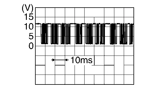
Is the inspection result normal?
YES>>Replace corresponding seat blower LH. Refer to Removal and Installation (seat back blower) or Removal and Installation (seat cushion blower).
NO>>GO TO 5.
CHECK SEAT BLOWER LH SIGNAL CIRCUIT (OPEN)
Ignition switch OFF.
Disconnect front seat heater LH connector.
Check continuity between seat cushion blower LH harness connector, seat back blower LH harness connector and front seat heater LH harness connector.
Seat cushion blower Seat cushion blower LH Front seat heater LH Continuity Connector Terminal Connector Terminal B233 2 B232 4 Yes Seat cushion blower Seat back blower LH Front seat heater LH Continuity Connector Terminal Connector Terminal B234 2 B232 4 Yes
Is the inspection result normal?
YES>>GO TO 6.
NO>>Repair the harness or connector.
CHECK SEAT BLOWER LH SIGNAL CIRCUIT (SHORT TO GROUND)
Check continuity between seat cushion blower LH harness connector, seat back blower LH harness connector and ground.
| Seat cushion blower LH | — | Continuity | |
|---|---|---|---|
| Connector | Terminal | ||
| B233 | 2 | Ground | No |
| Seat cushion blower LH | — | Continuity | |
|---|---|---|---|
| Connector | Terminal | ||
| B234 | 2 | Ground | No |
Is the inspection result normal?
YES>>Replace seat cushion heater LH. Refer to Seat Cushion.
NO>>Repair the harness or connector.
Walk in Switch Nissan Pathfinder Fifth generation
Component Function Check
CHECK WALK IN SWITCH FUNCTION
Open door.
Ignition switch ON.
Check that the second row seat power walk in system operates when using the walk in side switch and walk in back switch.
Is the inspection result normal?
YES>>Walk in switch function is OK.
NO>>Refer to Diagnosis Procedure.
Diagnosis Procedure
CHECK WALK IN SWITCH SIGNAL CIRCUIT
Open door.
Ignition switch OFF.
Disconnect walk in side switch (left) connector, walk in side switch (right) connector, walk in back switch (left) connector and walk in back switch (right) connector.
Ignition switch ON.
Check voltage between walk in side switch (left) harness connector, walk in side switch (right) harness connector, walk in back switch (left) harness connector, walk in back switch (right) harness connector and ground.
Walk in side switch (+) (-) Voltage
(Approx.)Walk in side switch Connector Terminal LH B528 2 Ground Battery voltage RH B561 Walk in back switch (+) (-) Voltage
(Approx.)Walk in back switch Connector Terminal LH B529 2 Ground Battery voltage RH B562
Is the inspection result normal?
YES>>GO TO 4.
NO>>GO TO 2.
CHECK WALK IN SWITCH SIGNAL CIRCUIT (OPEN)
Ignition switch OFF.
Disconnect second row seat power walk in control unit connector.
Check continuity between walk in side switch (left) harness connector, walk in side switch (right) harness connector, walk in back switch (left) harness connector, walk in back switch (right) harness connector and second row seat power walk in control unit harness connector.
Walk in side switch Walk in side switch Second row seat power walk in control unit Continuity Connector Terminal Connector Terminal LH B528 2 B555 5 Yes RH B561 21 Walk in back switch Walk in back switch Second row seat power walk in control unit Continuity Connector Terminal Connector Terminal LH B529 2 B555 20 Yes RH B562 13
Is the inspection result normal?
YES>>GO TO 3.
NO>>Repair the harness or connector.
CHECK WALK IN SWITCH SIGNAL CIRCUIT (SHORT TO GROUND)
Check continuity between walk in side switch (left) harness connector, walk in side switch (right) harness connector, walk in back switch (left) harness connector, walk in back switch (right) harness connector and ground.
| Walk in side switch | (-) | Continuity | ||
|---|---|---|---|---|
| Connector | Terminal | |||
| LH | B528 | 2 | Ground | No |
| RH | B561 | |||
| Walk in back switch | (-) | Continuity | ||
|---|---|---|---|---|
| Connector | Terminal | |||
| LH | B529 | 2 | Ground | No |
| RH | B562 | |||
Is the inspection result normal?
YES>>Replace second row seat power walk in control unit. Refer to Removal and Installation.
NO>>Repair the harness or connector.
CHECK WALK IN SWITCH GROUND CIRCUIT (OPEN)
Ignition switch OFF.
Disconnect second row seat power walk in control unit connector.
Check continuity between walk in side switch (left) harness connector, walk in side switch (right) harness connector, walk in back switch (left) harness connector, walk in back switch (right) harness connector and second row seat power walk in control unit harness connector.
Walk in side switch Walk in side switch Second row seat power walk in control unit Continuity Connector Terminal Connector Terminal LH B528 1 B555 4 Yes RH B561 Walk in back switch Walk in back switch Second row seat power walk in control unit Continuity Connector Terminal Connector Terminal LH B529 1 B555 4 Yes RH B562
Is the inspection result normal?
YES>>GO TO 5.
NO>>Repair the harness or connector.
CHECK WALK IN SWITCH
Check walk in switch. Refer to Component Inspection.
Is the inspection result normal?
YES>>GO TO 6.
NO>>Replace corresponding walk in switch. Refer to Removal and Installation (walk in side switch) or Removal and Installation (walk in back switch).
CHECK WALK IN SWITCH INDICATOR SIGNAL CIRCUIT
Connect walk in switch connector and second row seat power walk in control unit connector.
Fold the second row seat back flat using the manual adjuster.
Ignition switch ON.
Check voltage between walk in side switch (left) harness connector, walk in side switch (right) harness connector, walk in back switch (left) harness connector, walk in back switch (right) harness connector and ground while pressing the walk in switch.
Walk in side switch (+) (-) Voltage
(Approx.)Walk in side switch Connector Terminal LH B528 4 Ground Blinking: 0 V <–> Battery voltage RH B561 Walk in back switch (+) (-) Voltage
(Approx.)Walk in back switch Connector Terminal LH B529 4 Ground Blinking: 0 V <–> Battery voltage RH B562
Is the inspection result normal?
YES>>GO TO 9.
NO>>GO TO 7.
CHECK WALK IN SWITCH INDICATOR SIGNAL CIRCUIT (OPEN)
Ignition switch OFF.
Disconnect walk in side switch (left) connector, walk in side switch (right) connector, walk in back switch (left) connector, walk in back switch (right) connector and second row seat power walk in control unit connector.
Check continuity between walk in side switch (left) harness connector, walk in side switch (right) harness connector, walk in back switch (left) harness connector, walk in back switch (right) harness connector and second row seat power walk in control unit harness connector.
Walk in side switch Walk in side switch Second row seat power walk in control unit Continuity Connector Terminal Connector Terminal LH B528 4 B555 22 Yes RH B561 Walk in back switch Walk in back switch Second row seat power walk in control unit Continuity Connector Terminal Connector Terminal LH B529 4 B555 22 Yes RH B562
Is the inspection result normal?
YES>>GO TO 8.
NO>>Repair the harness or connector.
CHECK WALK IN SWITCH INDICATOR CIRCUIT (SHORT TO GROUND)
Check continuity between walk in side switch (left) harness connector, walk in side switch (right) harness connector, walk in back switch (left) harness connector, walk in back switch (right) harness connector and ground.
| Walk in side switch | (-) | Continuity | ||
|---|---|---|---|---|
| Connector | Terminal | |||
| LH | B528 | 4 | Ground | No |
| RH | B561 | |||
| Walk in back switch | (-) | Continuity | ||
|---|---|---|---|---|
| Connector | Terminal | |||
| LH | B529 | 4 | Ground | No |
| RH | B562 | |||
Is the inspection result normal?
YES>>Replace second row seat power walk in control unit. Refer to Removal and Installation.
NO>>Repair the harness or connector.
CHECK WALK IN SWITCH INDICATOR GROUND CIRCUIT (OPEN)
Ignition switch OFF.
Disconnect walk in side switch (left) connector, walk in side switch (right) connector, walk in back switch (left) connector and walk in back switch (right) connector.
Check continuity between walk in side switch (left) harness connector, walk in side switch (right) harness connector, walk in back switch (left) harness connector, walk in back switch (right) harness connector and ground.
Walk in side switch Walk in side switch (-) Continuity Connector Terminal LH B528 3 Ground Yes RH B561 Walk in back switch Walk in back switch (-) Continuity Connector Terminal LH B529 3 Ground Yes RH B562
Is the inspection result normal?
YES>>Replace corresponding walk in switch. Refer to Removal and Installation (walk in side switch) or Removal and Installation (walk in back switch).
NO>>Repair the harness or connector.
Component Inspection
CHECK WALK IN SWITCH
Ignition switch OFF.
Disconnect walk in switch connector.
Check continuity between walk in switch terminals.
Walk in switch Condition Continuity Terminal 2 1 Pressed Yes Not pressed No
Is the inspection result normal?
YES>>Inspection End.
NO>>Replace corresponding walk in switch. Refer to Removal and Installation (walk in side switch) or Removal and Installation (walk in back switch).
Seat Angle Sensor Nissan Pathfinder 2022
Component Function Check
CHECK SECOND ROW SEAT POWER WALK IN FUNCTION
Open door.
Ignition switch ON
Check that the second row seat power walk in system operates when using the walk in side switch or walk in back switch.
Is the inspection result normal?
YES>>Seat angle sensor function is OK.
NO>>Refer to Diagnosis Procedure.
Diagnosis Procedure
CHECK SEAT ANGLE SENSOR SIGNAL CIRCUIT
Open door.
Ignition switch OFF.
Disconnect seat angle sensor (left) connector and seat angle sensor (right) connector.
Ignition switch ON.
Check voltage between seat angle sensor (left) harness connector, seat angle sensor (right) harness connector and ground.
(+) (-) Voltage
(Approx.)Seat angle sensor Connector Terminal LH B524 1 Ground Battery voltage RH B563
Is the inspection result normal?
YES>>GO TO 4.
NO>>GO TO 2.
CHECK SEAT ANGLE SENSOR SIGNAL CIRCUIT (OPEN)
Ignition switch OFF.
Disconnect second row seat power walk in control unit connector.
Check continuity between seat angle sensor (left) harness connector, seat angle sensor (right) harness connector and second row seat power walk in control unit harness connector.
Seat angle sensor Second row seat power walk in control unit Continuity Connector Terminal Connector Terminal LH B524 1 B555 11 Yes RH B563 10
Is the inspection result normal?
YES>>GO TO 3.
NO>>Repair the harness or connector.
CHECK SEAT ANGLE SENSOR SIGNAL CIRCUIT (SHORT TO GROUND)
Check continuity between seat angle sensor (left) harness connector, seat angle sensor (right) harness connector and ground.
| Seat angle sensor | (-) | Continuity | ||
|---|---|---|---|---|
| Connector | Terminal | |||
| LH | B524 | 1 | Ground | No |
| RH | B563 | |||
Is the inspection result normal?
YES>>Replace second row seat power walk in control unit. Refer to Removal and Installation.
NO>>Repair the harness or connector.
CHECK SEAT ANGLE SENSOR GROUND CIRCUIT (OPEN)
Ignition switch OFF.
Disconnect second row seat power walk in control unit connector.
Check continuity between seat angle sensor (left) harness connector, seat angle sensor (right) harness connector and second row seat power walk in control unit harness connector.
Seat angle sensor Second row seat power walk in control unit Continuity Connector Terminal Connector Terminal LH B524 2 B555 2 Yes RH B563 3
Is the inspection result normal?
YES>>GO TO 5.
NO>>Repair the harness or connector.
CHECK SEAT ANGLE SENSOR
Check seat angle sensor. Refer to Component Inspection.
Is the inspection result normal?
YES>>Check intermittent incident. Refer to Intermittent Incident.
NO>>Replace corresponding seat angle sensor. Refer to Exploded View.
Component Inspection
CHECK SEAT ANGLE SENSOR
Ignition switch OFF.
Disconnect seat angle sensor connector.
Check continuity between seat angle sensor terminals with the second row seat back folded flat and upright.
Walk in switch Condition Continuity Terminal 1 2 Flat No Upright Yes
Is the inspection result normal?
YES>>Inspection End.
NO>>Replace corresponding seat angle sensor. Refer to Exploded View.
Seat Walk in Motor Nissan Pathfinder 5th Gen
Component Function Check
CHECK SECOND ROW SEAT POWER WALK IN FUNCTION
Open door.
Ignition switch ON
Check that the second row seat power walk in system operates when using the walk in side switch or walk in back switch.
Is the inspection result normal?
YES>>Seat walk in motor function is OK.
NO>>Refer to Diagnosis Procedure.
Diagnosis Procedure
CHECK SEAT WALK IN MOTOR POWER SUPPLY CIRCUIT
Open door.
Ignition switch OFF.
Disconnect seat walk in motor (left) connector and seat walk in motor (right) connector.
Ignition switch ON.
With operating the walk in switch, check voltage between seat walk in motor (left) harness connector, seat walk in motor (right) harness connector and ground.
(+) (-) Condition Voltage
(Approx.)Seat walk in motor Connector Terminal LH B525 2 Ground Walk in switch Pressed Battery voltage RH B564 Released 0 V
Is the inspection result normal?
YES>>GO TO 4.
NO>>GO TO 2.
CHECK SEAT WALK IN MOTOR POWER SUPPLY CIRCUIT (OPEN)
Ignition switch OFF.
Disconnect second row seat power walk in control unit connector.
Check continuity between seat walk in motor (left) harness connector, seat walk in motor (right) harness connector and second row seat power walk in control unit harness connector.
Seat walk in motor Second row seat power walk in control unit Continuity Connector Terminal Connector Terminal LH B525 2 B555 16 Yes RH B564 8
Is the inspection result normal?
YES>>GO TO 3.
NO>>Repair the harness or connector.
CHECK SEAT WALK IN MOTOR POWER SUPPLY CIRCUIT (SHORT TO GROUND)
Check continuity between seat walk in motor (left) harness connector, seat walk in motor (right) harness connector and ground.
| Seat walk in motor | (-) | Continuity | ||
|---|---|---|---|---|
| Connector | Terminal | |||
| LH | B525 | 2 | Ground | No |
| RH | B564 | |||
Is the inspection result normal?
YES>>Replace second row seat power walk in control unit. Refer to Removal and Installation.
NO>>Repair the harness or connector.
CHECK SEAT WALK IN MOTOR GROUND CIRCUIT (OPEN)
Ignition switch OFF.
Disconnect second row seat power walk in control unit connector.
Check continuity between seat walk in motor (left) harness connector, seat walk in motor (right) harness connector and second row seat power walk in control unit harness connector.
Seat walk in motor Second row seat power walk in control unit Continuity Connector Terminal Connector Terminal LH B525 1 B555 1 Yes RH B564 9
Is the inspection result normal?
YES>>Replace corresponding seat walk in motor. Refer to Removal and Installation.
NO>>Repair the harness or connector.
Power Supply and Ground Circuit. Second Row Seat Power Walk in Control Unit Nissan Pathfinder R53
Diagnosis Procedure
CHECK FUSE
Check that the following fuse is not blown:
| Terminal No. | Signal name | Fuse No. | Capacity |
|---|---|---|---|
| 24 | Battery power supply | 58 | 15A |
Is the fuse or fusible link blown?
YES>>Replace the blown fuse after repairing the affected circuit.
NO>>GO TO 2.
CHECK POWER SUPPLY CIRCUIT
Disconnect second row seat power walk in control unit connector.
Check voltage between second row seat power walk in control unit harness connector and ground.
+ – Voltage
(Approx.)Second row seat power walk in control unit Connector Terminal B555 24 Ground Battery voltage
Is the inspection result normal?
YES>>GO TO 3.
NO>>Repair harness or connector.
CHECK GROUND CIRCUIT
Check continuity between second row seat power walk in control unit harness connector and ground.
| Second row seat power walk in control unit | — | Continuity | |
|---|---|---|---|
| Connector | Terminal | ||
| B555 | 17 | Ground | Yes |
Is the inspection result normal?
YES>>Inspection End.
NO>>Repair harness or connector.