Fuel System - Removal and Installation

In this manual: Fuel System - Removal and Installation
General Information — 8Engine :: Engine Mechanical — 19Engine Lubrication System - Precautions. Preparation — 1Engine Lubrication System - Lubrication System (System Description). Engine Oil Pressure (Basic Inspection). Service Data and Specifications (SDS) — 1Engine Cooling System - Precautions. Preparation. Service Data and Specifications (SDS) — 1Engine Cooling System - Engine Coolant — 1Engine Control System - System Description — 1System Description - Component Parts ++ — 1System Description - System ++ — 1Engine Control System - Ecu Diagnosis Information — 1Ecu Diagnosis Information - Ecm ++ — 1Engine Control System - Basic Inspection — 1Basic Inspection - Diagnosis and Repair Workflow ++ — 1Basic Inspection - Basic Inspection ++ — 1Basic Inspection - Additional Service When Replacing Ecm ++ — 1Basic Inspection - Fuel Pressure Check ++ — 1Basic Inspection - How to Set Srt Code ++ — 1Basic Inspection - How to Erase Permanent Dtc ++ — 1Engine Control System - Dtc/circuit Diagnosis — 1Engine Control System - Symptom Diagnosis — 1Engine Control System - Periodic Maintenance — 1Engine Control System - Removal and Installation — 1Fuel System - Precautions. Preparation. Service Data and Specifications (SDS) — 1Fuel System - Fuel System (Periodic Maintenance). Fuel Level Sensor Unit (Disassembly and Assembly) — 1Exhaust System - Precautions. Preparation — 1Exhaust System - Exhaust System (Periodic Maintenance). Exhaust System (Removal and Installation) — 1Starting System - Precautions. Preparation. Starter Motor (Service Data and Specifications (sds)) — 1Starting System - Diagnosis and Repair Work Flow — 1Starting System - Starting System (Symptom Diagnosis). Starter Motor (Removal and Installation) — 1Accelerator Control System - Precautions. Service Data and Specifications (SDS) — 1Accelerator Control System - Accelerator Pedal Assembly — 1Transmission & Driveline :: Transaxle & Transmission — 21Driveline - System Description — 1Transfer: Ty92b - Ecu Diagnosis Information. Awd Control Unit ++ — 1Driveline - Basic Inspection — 1Driveline - Dtc/circuit Diagnosis — 1Driveline - Symptom Diagnosis — 1Driveline - Removal and Installation — 1Transfer: Ty92b - Unit Removal and Installation. Transfer Assembly ++ — 1Driveline - Unit Disassembly and Assembly — 1Driveline - Basic Inspection — 1Driveline - Removal and Installation — 1Driveline - Unit Disassembly and Assembly — 1Front Axle - Precautions. Preparation — 1Front Axle - Noise, Vibration and Harshness (nvh) Troubleshooting (Symptom Diagnosis). Service Data and Specifications (SDS) — 1Front Axle - Front Drive Shaft Boot — 1Front Axle - Front Drive Shaft — 1Rear Axle - Precautions. Preparation. Service Data and Specifications (SDS) — 1Rear Axle - Noise, Vibration and Harshness (nvh) Troubleshooting — 1Rear Axle - Rear Drive Shaft — 1Suspension :: Front Suspension — 7Rear Suspension - Precautions. Preparation — 1Rear Suspension - Noise, Vibration and Harshness (nvh) Troubleshooting (Symptom Diagnosis). Service Data and Specifications (SDS) — 1Rear Suspension - Rear Suspension Assembly — 1Road Wheels & Tires - Precautions — 1Road Wheels & Tires - Preparation. Bcm (Ecu Diagnosis Information). Service Data and Specifications (SDS) — 1Road Wheels & Tires - System — 1Brakes :: Brake System — 9Parking Brake System - Precautions. Preparation — 1Parking Brake System - System — 1Vdc/tcs/abs - Precautions ++ — 1Brake Control System - System Description — 1System Description - Component Parts ++ — 1System Description - System ++ — 1Brake Control System - Basic Inspection — 1Brake Control System - Symptom Diagnosis — 1Brake Control System - Removal and Installation — 1Brake Control System - System Description — 1Brake Control System - Dtc/circuit Diagnosis — 1Brake Control System - Removal and Installation — 1Brake Control System - System Description — 1Brake Control System - Basic Inspection — 1Brake Control System - Symptom Diagnosis — 1Brake Control System - System Description — 1Brake Control System - Basic Inspection — 1Brake Control System - Symptom Diagnosis — 1Steering :: Steering System — 9Steering Control System - Precautions — 1Steering Control System - System — 1Steering Control System - Eps Control Unit (Ecu Diagnosis Information. Removal and Installation) — 1Restraints :: Seat Belt — 7Srs Air Bag - Precautions. Preparation — 1Srs Air Bag - Collision Diagnosis — 1Srs Air Bag - Occupant Classification System — 1Srs Air Bag Control System - Precautions — 1Srs Air Bag Control System - System — 1Srs Air Bag Control System - Diagnosis Sensor Unit — 1Srs Air Bag Control System - Inspection and Adjustment — 1Ventilation, Heater & Air Conditioner :: Ventilation System — 6Heater & Air Conditioning System - Precautions — 1Heater & Air Conditioning System - Preparation — 1Heater & Air Conditioning System - Component Parts — 1Heater & Air Conditioning System - Diagnosis and Repair Work Flow — 1Heater & Air Conditioning System - Compressor — 1Heater & Air Conditioning System - Cooler Pipe and Hose — 1Heater & Air Conditioning System - Condenser. Condenser — 1Heater & Air Conditioning System - Heating and Cooling Unit Assembly — 1Heater & Air Conditioning System - Service Data and Specifications (SDS) — 1Heater & Air Conditioning Control System - System Description — 1System Description - Component Parts ++ — 1System Description - System ++ — 1System Description - Operation ++ — 1Heater & Air Conditioning Control System - Ecu Diagnosis Information — 1Heater & Air Conditioning Control System - Basic Inspection — 1Heater & Air Conditioning Control System - Dtc/circuit Diagnosis — 1Heater & Air Conditioning Control System - Symptom Diagnosis — 1Heater & Air Conditioning Control System - Removal and Installation — 1Body Interior :: Interior — 8Instrument Panel - Precautions. Preparation. Clip List — 1Instrument Panel - Squeak and Rattle Trouble Diagnoses — 1Instrument Panel - Cluster Lid C — 1Seat - Precautions — 1Seat - Preparation. Clip List — 1Seat - Component Parts — 1Seat - System — 1Seat - Diagnosis and Repair Work Flow — 1Seat - Front Seat — 1Seat - Second Row Seats — 1Seat - Third Row Seats — 1Seat - Front Seat — 1Seat - Second Row Seat — 1Seat - Third Row Seat — 1Automatic Drive Positioner - Precautions. Preparation — 1Automatic Drive Positioner - System — 1Automatic Drive Positioner - Diagnosis and Repair Work Flow — 1Automatic Drive Positioner - Inspection and Adjustment — 1Body Exterior, Doors, Roof & Vehicle Security :: Door & Lock — 38Security Control System - Precautions — 1Security Control System - System — 1Security Control System - Ecm, Bcm, Intelligent Key Unit, Ipdm E/r — 1Security Control System - Vehicle Security System Cannot Be Set — 1Glass & Window System - Precautions. Preparation — 1Glass & Window System - Squeak and Rattle Trouble Diagnoses — 1Power Window Control System - Precautions. Preparation — 1Power Window Control System - Power Supply and Ground Circuit — 1Power Window Control System - Power Window Motor Circuit — 1Power Window Control System - Front Power Window Rh Alone Does Not Operate — 1Power Window Control System - Rear Lh Side Power Window Alone Does Not Operate — 1Power Window Control System - Rear Rh Side Power Window Alone Does Not Operate — 1Roof - Precautions. Preparation — 1Roof - Power Supply and Ground Circuit — 1Roof - Moonroof Switch Assembly — 1Roof - Lin Communication Circuit — 1Roof - Auto Operation Does Not Operate — 1Roof - Anti-Pinch Function Does Not Operate — 1Exterior - Precautions. Preparation. Clip List (Preparation) — 1Exterior - Squeak and Rattle Trouble Diagnoses — 1Exterior - Fender Protector — 1Exterior - Over Fender — 1Exterior - Under Cover — 1Exterior - Roof Side Rail — 1Body Repair - Service Information — 1Service Information - Sheet Metal Work ++ — 1Service Information - Body Welding and Precautions ++ — 1Service Information - Safety and Health ++ — 1Service Information - Repairing Procedures and Precautions ++ — 1Body Repair - Precaution — 1Body Repair - Preparation — 1Body Repair - Removal and Installation — 1Driver Controls :: Mirrors — 8Exterior Lighting System - System Description — 1System Description - Component Parts ++ — 1Exterior Lighting System - Basic Inspection — 1Exterior Lighting System - Dtc/circuit Diagnosis — 1Exterior Lighting System - Symptom Diagnosis — 1Exterior Lighting System - Periodic Maintenance — 1Exterior Lighting System - Removal and Installation — 1Interior Lighting System - Precautions. Preparation — 1Interior Lighting System - Component Parts. Interior Lighting System — 1Interior Lighting System - System — 1Interior Lighting System - Diagnosis and Repair Work Flow — 1Interior Lighting System - Interior Lighting System Symptoms (Symptom Diagnosis). Bcm (Ecu Diagnosis Information). Service Data and Specifications (SDS) — 1Interior Lighting System - Foot Lamp — 1Wiper & Washer - Precautions — 1Wiper & Washer - Preparation. Bcm, Ipdm E/r (Ecu Diagnosis Information). Service Data and Specifications (SDS) — 1Wiper & Washer - System — 1Wiper & Washer - Diagnosis and Repair Work Flow — 1Defogger - Precautions. Bcm, A/c Auto Amp. (Ecu Diagnosis Information) — 1Defogger - Diagnosis and Repair Work Flow — 1Horn - Precautions — 1Electrical & Power Control :: Power Outlet — 13Body Control System - Precautions. Preparation — 1Body Control System - Component Parts — 1Body Control System - System — 1Body Control System - Diagnosis System (bcm) — 1Body Control System - Bcm — 1Lan System - System Description — 1Lan System - System Description — 1Lan System - Dtc/circuit Diagnosis — 1Lan System - System Description — 1Lan System - Dtc/circuit Diagnosis — 1Power Control System - System Description — 1Power Control System - Basic Inspection — 1Power Control System - Dtc/circuit Diagnosis — 1Power Control System - System Description — 1Power Control System - Basic Inspection — 1Power Control System - Dtc/circuit Diagnosis — 1Power Control System - Removal and Installation — 1Charging System - Precautions. Preparation. Ecm, Ipdm E/r (Ecu Diagnosis Information) — 1Charging System - Diagnosis and Repair Work Flow — 1Charging System - Charging System (Symptom Diagnosis). Generator (Removal and Installation). Service Data and Specifications (SDS) — 1Power Supply, Ground & Circuit Elements - Precautions. Preparation. Service Data and Specifications (SDS) — 1Driver Information & Multimedia :: Meter, Warning Lamp & Indicator — 25Warning Chime System - Application Notice (How to Use This Manual). Precautions — 1Warning Chime System - System — 1Warning Chime System - Diagnosis System (combination Meter) — 1Warning Chime System - Bcm, Combination Meter (Ecu Diagnosis Information). Diagnosis and Repair Work Flow (Basic Inspection) — 1Sonar System - Precautions. Preparation — 1Sonar System - Sonar Control Unit — 1Dtc/circuit Diagnosis - B2720 Corner Sensor [rl] ++ — 1Audio, Visual & Navigation System - System Description — 1System Description - Component Parts ++ — 1System Description - System ++ — 1Audio, Visual & Navigation System - Ecu Diagnosis Information — 1Audio, Visual & Navigation System - Basic Inspection — 1Audio, Visual & Navigation System - Dtc/circuit Diagnosis — 1Dtc/circuit Diagnosis - Multi Av (av Control Unit) ++ — 1Audio, Visual & Navigation System - Symptom Diagnosis — 1Symptom Diagnosis - Multi Av System ++ — 1Audio, Visual & Navigation System - Removal and Installation — 1Audio, Visual & Navigation System - System Description — 1Audio, Visual & Navigation System - Ecu Diagnosis Information — 1Audio, Visual & Navigation System - Basic Inspection — 1Audio, Visual & Navigation System - Dtc/circuit Diagnosis — 1Audio, Visual & Navigation System - Symptom Diagnosis — 1Audio, Visual & Navigation System - Removal and Installation — 1Audio, Visual & Navigation System - System Description — 1Audio, Visual & Navigation System - Basic Inspection — 1Audio, Visual & Navigation System - Dtc/circuit Diagnosis — 1Audio, Visual & Navigation System - Symptom Diagnosis — 1Audio, Visual & Navigation System - Removal and Installation — 1Audio, Visual & Navigation System - System Description — 1Audio, Visual & Navigation System - Basic Inspection — 1Audio, Visual & Navigation System - Dtc/circuit Diagnosis — 1Audio, Visual & Navigation System - Symptom Diagnosis — 1Audio, Visual & Navigation System - Removal and Installation — 1Cruise Control & Driver Assistance :: Cruise Control System — 17Driver Assistance System - System Description — 1Driver Assistance System - Basic Inspection — 1Driver Assistance System - Dtc/circuit Diagnosis — 1Driver Assistance System - System Description — 1System Description - Component Parts ++ — 1System Description - System ++ — 1System Description - Operation ++ — 1System Description - Handling Precaution ++ — 1Driver Assistance System - Ecu Diagnosis Information — 1Driver Assistance System - Basic Inspection — 1Basic Inspection - Distance Sensor Alignment ++ — 1Basic Inspection - Camera Aiming Adjustment ++ — 1Basic Inspection - Action Test ++ — 1Driver Assistance System - Dtc/circuit Diagnosis — 1Dtc/circuit Diagnosis - Laser/radar (distance Sensor) ++ — 1Dtc/circuit Diagnosis - Lane Camera (front Camera Unit) ++ — 1Driver Assistance System - Symptom Diagnosis — 1Driver Assistance System - Removal and Installation — 1Driver Assistance System - System Description — 1System Description - System ++ — 1Driver Assistance System - Basic Inspection — 1Driver Assistance System - Dtc/circuit Diagnosis — 1Drive Mode System - Precautions — 1Drive Mode System - Component Parts. Drive Mode System — 1Drive Mode System - System — 1Drive Mode System - Diagnosis and Repair Work Flow — 1Drive Mode System - Drive Mode Select Switch Circuit — 1Maintenance - Precautions. Preparation — 1Maintenance - General Maintenance — 1Maintenance - Periodic Maintenance — 1Maintenance - Recommended Fluids and Lubricants — 1Maintenance - Engine Maintenance — 1Maintenance - Chassis and Body Maintenance — 1Engine Lubrication System - Periodic Maintenance — 1Engine Lubrication System - Removal and Installation — 1Engine Cooling System - System Description — 1Engine Cooling System - Removal and Installation — 1Engine Control System - Vq35dd — 1Fuel System - Removal and Installation — 1Starting System - System Description — 1Starting System - Dtc/circuit Diagnosis — 1Driveline - Transfer: Ty92b — 1Driveline - Rear Propeller Shaft: 3fcj-Cvj — 1Driveline - Rear Final Drive: R145 — 1Front Axle - Periodic Maintenance — 1Front Axle - Removal and Installation — 1Rear Axle - Periodic Maintenance — 1Rear Axle - Removal and Installation — 1Rear Suspension - Removal and Installation — 1Road Wheels & Tires - System Description — 1Road Wheels & Tires - Basic Inspection — 1Road Wheels & Tires - Dtc/circuit Diagnosis — 1Road Wheels & Tires - Symptom Diagnosis — 1Road Wheels & Tires - Periodic Maintenance — 1Road Wheels & Tires - Removal and Installation — 1Parking Brake System - System Description — 1Parking Brake System - Basic Inspection — 1Parking Brake System - Dtc/circuit Diagnosis — 1Parking Brake System - Symptom Diagnosis — 1Parking Brake System - Removal and Installation — 1Brake Control System - Vdc/tcs/abs — 1Brake Control System - Automatic Brake Hold — 1Brake Control System - Automatic Emergency Braking — 1Brake Control System - Rear Automatic Braking — 1Steering Control System - System Description — 1Steering Control System - Basic Inspection — 1Steering Control System - Dtc/circuit Diagnosis — 1Steering Control System - Symptom Diagnosis — 1Srs Air Bag - Removal and Installation — 1Srs Air Bag Control System - System Description — 1Srs Air Bag Control System - Basic Inspection — 1Srs Air Bag Control System - Symptom Diagnosis — 1Heater & Air Conditioning System - Symptom Diagnosis — 1Heater & Air Conditioning System - Periodic Maintenance — 1Heater & Air Conditioning Control System - Automatic Air Conditioning — 1Instrument Panel - Removal and Installation — 1Instrument Panel - Unit Disassembly and Assembly — 1Seat - Ecu Diagnosis Information — 1Seat - Dtc/circuit Diagnosis — 1Seat - Symptom Diagnosis — 1Automatic Drive Positioner - System Description — 1Automatic Drive Positioner - Ecu Diagnosis Information — 1Automatic Drive Positioner - Dtc/circuit Diagnosis — 1Automatic Drive Positioner - Symptom Diagnosis — 1Automatic Drive Positioner - Removal and Installation — 1Security Control System - System Description — 1Security Control System - Basic Inspection — 1Security Control System - Dtc/circuit Diagnosis — 1Security Control System - Symptom Diagnosis — 1Security Control System - Removal and Installation — 1Glass & Window System - Removal and Installation — 1Power Window Control System - System Description — 1Power Window Control System - Ecu Diagnosis Information — 1Power Window Control System - Basic Inspection — 1Power Window Control System - Dtc/circuit Diagnosis — 1Power Window Control System - Symptom Diagnosis — 1Power Window Control System - Removal and Installation — 1Roof - System Description — 1Roof - Ecu Diagnosis Information — 1Roof - Basic Inspection — 1Roof - Dtc/circuit Diagnosis — 1Roof - Symptom Diagnosis — 1Roof - Removal and Installation — 1Exterior - System Description — 1Exterior - Removal and Installation — 1Body Repair - Repair Information — 1Exterior Lighting System - Led Headlamp — 1Interior Lighting System - Dtc/circuit Diagnosis — 1Interior Lighting System - Removal and Installation — 1Wiper & Washer - System Description — 1Wiper & Washer - Dtc/circuit Diagnosis — 1Wiper & Washer - Symptom Diagnosis — 1Wiper & Washer - Removal and Installation — 1Defogger - System Description — 1Defogger - Dtc/circuit Diagnosis — 1Defogger - Symptom Diagnosis — 1Defogger - Removal and Installation — 1Horn - Removal and Installation — 1Body Control System - Basic Inspection — 1Body Control System - Dtc/circuit Diagnosis — 1Body Control System - Symptom Diagnosis — 1Body Control System - Removal and Installation — 1Lan System - Can Fundamental — 1Lan System - Can — 1Lan System - Can Gateway — 1Power Control System - Ipdm E/r — 1Power Control System - Power Distribution System — 1Charging System - System Description — 1Charging System - Dtc/circuit Diagnosis — 1Power Supply, Ground & Circuit Elements - System Description — 1Power Supply, Ground & Circuit Elements - Basic Inspection — 1Power Supply, Ground & Circuit Elements - Removal and Installation — 1Warning Chime System - System Description — 1Warning Chime System - Dtc/circuit Diagnosis — 1Warning Chime System - Symptom Diagnosis — 1Sonar System - System Description — 1Sonar System - Basic Inspection — 1Sonar System - Dtc/circuit Diagnosis — 1Sonar System - Symptom Diagnosis — 1Sonar System - Removal and Installation — 1Audio, Visual & Navigation System - Nissanconnect — 1Audio, Visual & Navigation System - Intelligent Around View Monitor System — 1Audio, Visual & Navigation System - Rear View Monitor System — 1Audio, Visual & Navigation System - Telematics System — 1Driver Assistance System - Adas Control Unit 2 — 1Driver Assistance System - Driver Assistance System — 1Driver Assistance System - Chassis Control — 1Drive Mode System - Removal and Installation — 1Dtc/circuit Diagnosis (C053c Wheel Speed Sensor ... U2141 Can Comm Circuit) — 1Dtc/circuit Diagnosis (P0011 Intake Valve Timing Control ... P0111 Iat Sensor) — 1Dtc/circuit Diagnosis (P0116 Engine Coolant Temperature Sensor ... P025b Fuel Pump Module a) — 1Dtc/circuit Diagnosis (P026b Injection Timing ... P0420 Three Way Catalyst Function) — 1Dtc/circuit Diagnosis (P0441 Evap Control System ... P0524 Engine Oil Pressure) — 1Dtc/circuit Diagnosis (P0532 A/c Refrigerant Pressure Sensor ... P064d Ecm) — 1Dtc/circuit Diagnosis (P06da Engine Oil Pressure Control Solenoid Valve ... P1217 Engine Over Temperature) — 1Dtc/circuit Diagnosis (P1220 Fuel Pump Control Module (fpcm) ... P1574 Ascd Vehicle Speed Sensor) — 1Dtc/circuit Diagnosis (P1575 Brake Switch ... P2101 Electric Throttle Control Function) — 1Dtc/circuit Diagnosis (P2118 Throttle Control Motor ... P34ac Electric Intake Valve Timing Control Actuator) — 1Dtc/circuit Diagnosis (Active Grille Shutter ... High Pressure Fuel Pump) — 1Dtc/circuit Diagnosis (Ignition Signal ... Variable Induction Air System) — 14012 C1040 Emergency Brake — 14013 C106a Wheel Sensor — 14014 C1078-55 Not Configuration — 14015 C10b4-98 Overheat — 14016 B1001 Lap Pre-Tensioner Lh — 14017 B0001 Driver Air Bag Module — 14018 B100e Knee Air Bag Module Rh — 14019 B142x Collision Detection — 1Dtc/circuit Diagnosis (B20c7-11 A/c Clutch ... B24a6-11 in-Vehicle Sensor) — 1Dtc/circuit Diagnosis (B24a6-15 in-Vehicle Sensor ... U2140-87 Can Comm Err (ecm)) — 1Dtc/circuit Diagnosis (C1f00-1c Control Unit ... C1f04-61 Brake Sw/stop Lamp Sw) — 1Dtc/circuit Diagnosis (C1f05-49 Front Camera Unit ... C1f70-87 Ethernet Circuit) — 1
~22min read
0204060801004030N·mlb·ft
Tightening torque found on this page
  • Fuel Level Sensor Unit, Fuel Filter and Fuel Pump Assembly
  • Fuel Tank
  • Evap Canister
  • Evap Canister Filter
  • Evap Canister Vent Control Valve
  • Evap Control System Pressure Sensor
  • Evap Canister Volume Control Solenoid Valve

Fuel Level Sensor Unit, Fuel Filter and Fuel Pump Assembly Nissan Pathfinder 2022

Exploded View
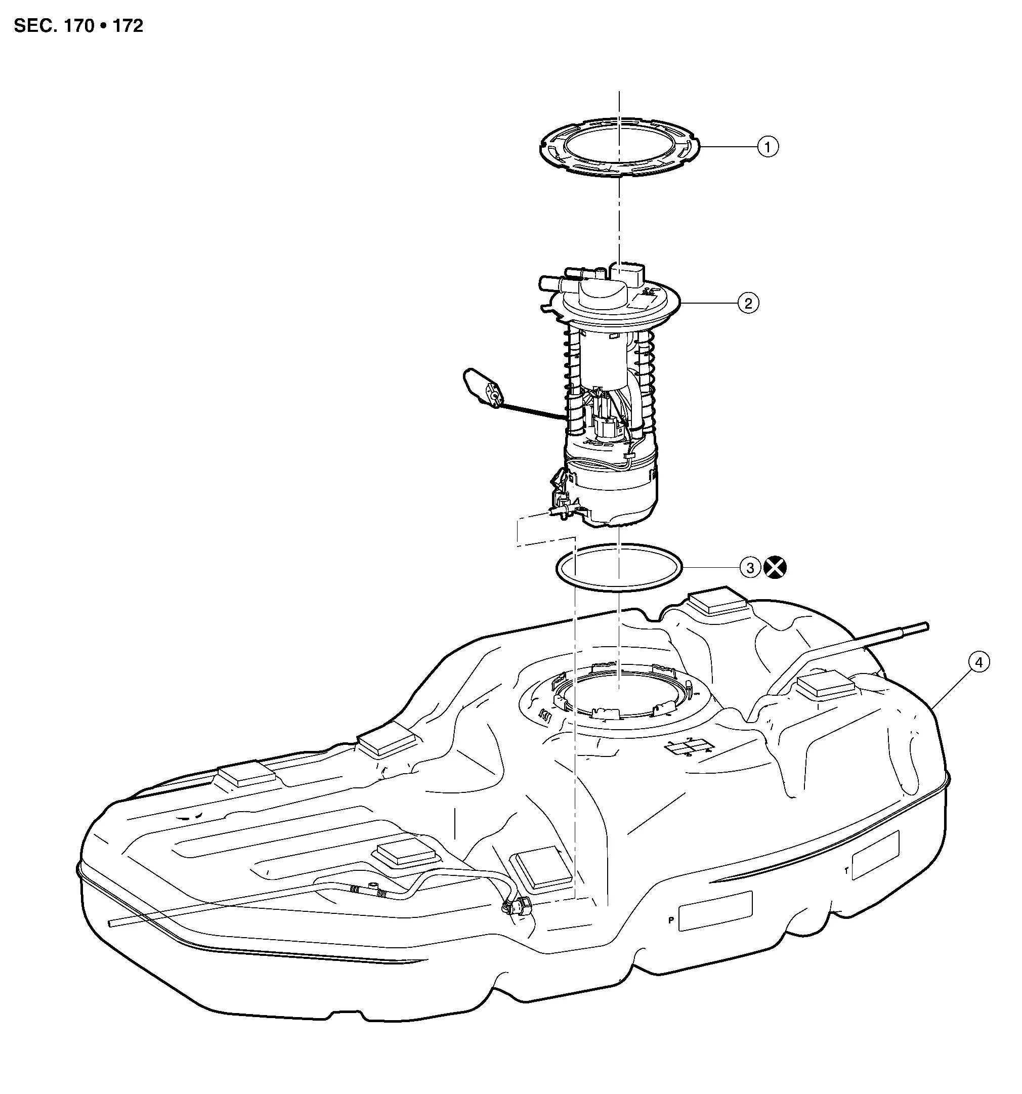
1. Lock ring 2. Fuel level sensor unit, fuel filter and fuel pump assembly 3. O-ring
4. Fuel tank

Removal and Installation

REMOVAL

Using suitable tool open filler neck valve to release the pressure inside the fuel tank.

Release the fuel pressure from the fuel lines. Refer to Work Procedure.

Remove second row seat (LH). Refer to Removal and Installation.

Position and secure the carpet to gain access to the fuel pump inspection hole cover.

Turn the four retainers (A) 90 degrees to disengage the clips and remove the fuel pump inspection hole cover.
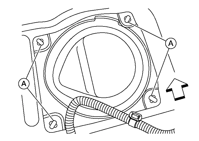
: Front

Disconnect the fuel level sensor unit, fuel filter, and fuel pump assembly harness connector (C), EVAP hose connector (A), and the fuel feed hose connector (B) from the fuel level sensor unit, fuel filter, and fuel pump assembly.
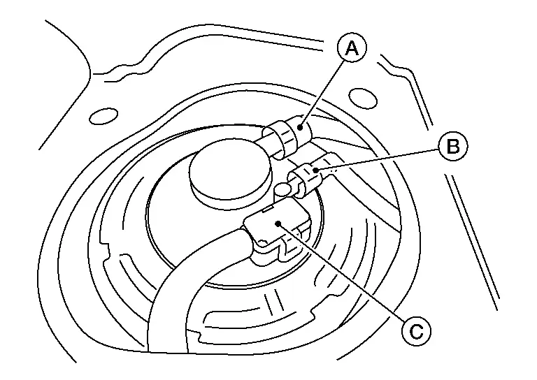
  • Disconnect the quick connector as follows:
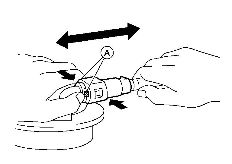
    • Hold the sides of the connector, push in tabs (A) and pull out the tube.

    • If the connector and the tube are stuck together, push and pull several times until they start to move. Then disconnect them by pulling.

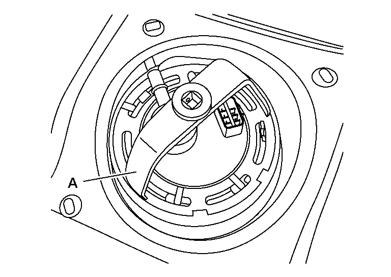
Remove the lock ring from the fuel level sensor unit, fuel filter, and fuel pump assembly.

  • Remove the lock ring using Tool (A).

    Tool number (A)

    : — (NI-45722) (shown)

    : KV101207S0 ( — )
    : Front
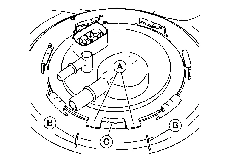
  • Prior to removal, observe the alignment between the fuel level sensor unit, fuel filter, and fuel pump assembly tabs (A) and the matching marks (B) on the fuel tank as shown. This alignment is necessary for proper installation.
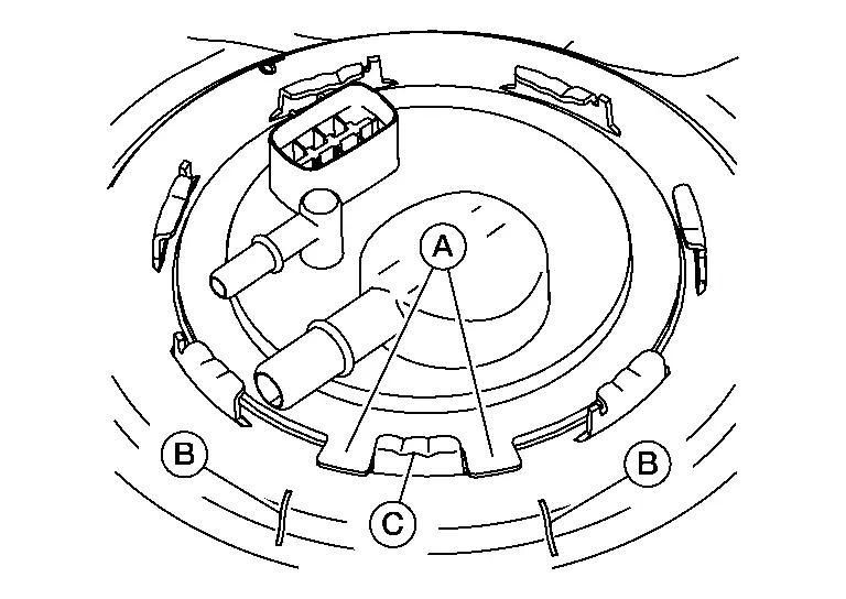
    (C) : Retainer pawl

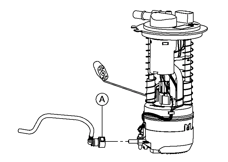
Raise the fuel level sensor unit, fuel filter, and fuel pump assembly high enough to gain access and disconnect the transfer tube connector (A).
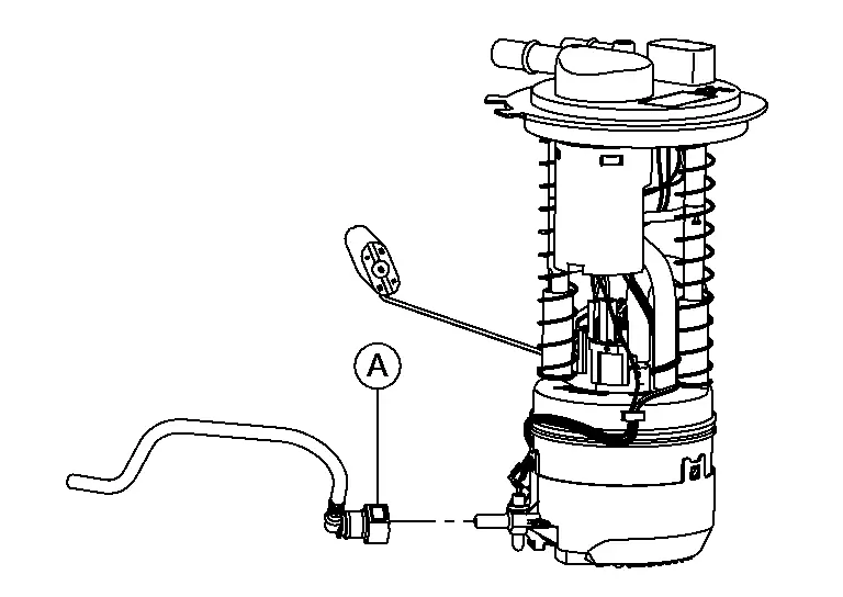
Remove the fuel level sensor unit, fuel filter, and fuel pump assembly and O-ring. Discard the O-ring.

INSPECTION AFTER REMOVAL

Inspect the fuel level sensor unit, fuel filter, and fuel pump for any defects and foreign materials. Replace as necessary.

INSTALLATION

Install the fuel level sensor, fuel filter, and fuel pump assembly with the following procedure:

  • Do not bend the float arm during installation.

Obtain a piece of plastic or nylon packing strap approximately 91cm (35.8 in).
  • Packing strap is commonly used to reinforce boxes for shipping.

Loop the packing strap (2) around the transfer hose as shown.
  • Position the strap ends toward the passenger side.

  • Use your fingers to put a bend (1) in the strap near the transfer hose (3). This will help keep the strap in place.
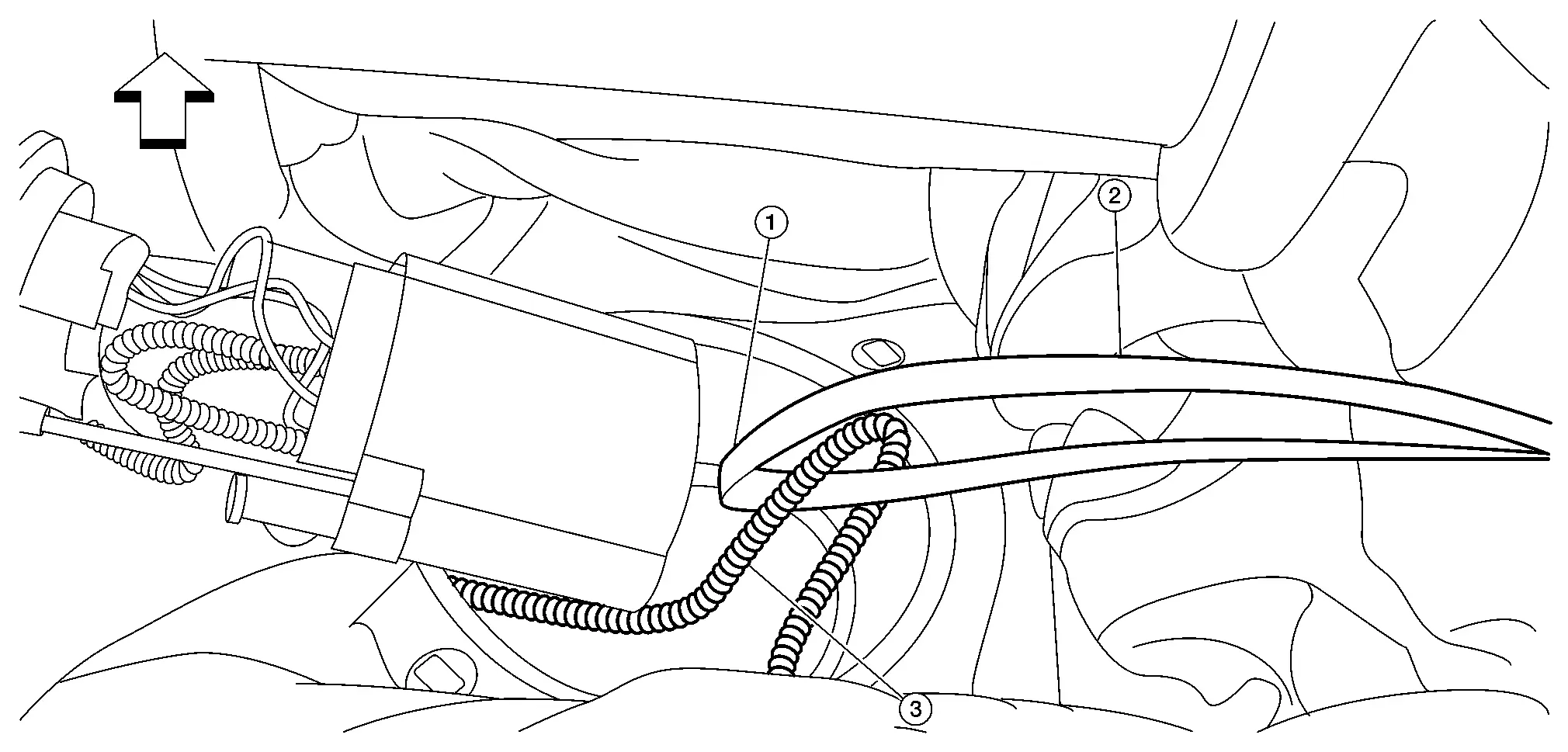
: Front

Lower the transfer hose and fuel level sensor unit, fuel filter and fuel pump assembly into the tank keeping the strap looped around the transfer hose. With the fuel level sensor unit, fuel filter and fuel pump assembly in the tank, turn 1/4 turn clockwise so the fuel feed port is pointing toward the passenger side.
  • The fuel level sensor unit, fuel filter and fuel pump assembly should now be oriented to the installed position.

Tilt the top of the fuel pump toward the driver side. Pull up on the packing strap (pull the transfer hose up) just enough to see the transfer hose. Hold the fuel pump down so the bottom of the pump stays against the bottom of the tank. While holding the pump down, pull out the packing strap, pull towards the passenger side.
  • Make sure the O-ring is still in place.

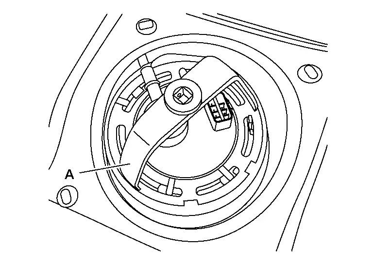
Continue to hold down the fuel pump while installing the fuel pump lock ring (turn clockwise) using Tool (A).
Tool number (A)

: — (NI-45722) (shown)

: KV101207S0 ( — )

: Front

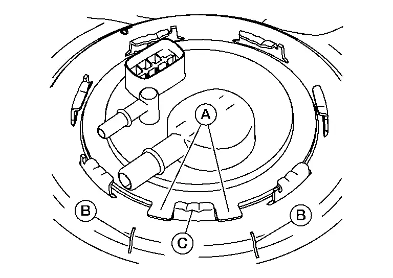
Align the tabs (A) of the fuel level sensor unit, fuel filter, and fuel pump assembly to the matching marks (B) of the fuel tank for proper installation.

(C) : Retainer pawl

Reconnect the EVAP hose (A), fuel feed hose (B) and harness connector (C).
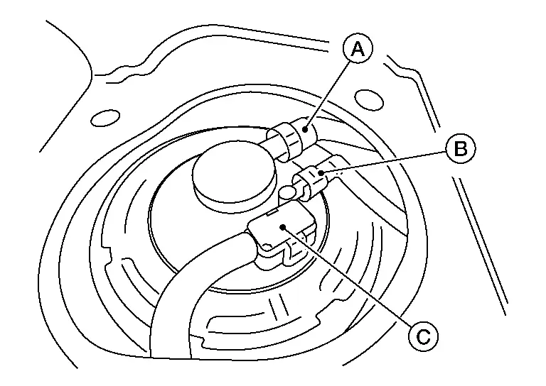
  • Check the connection for damage or any foreign materials.

  • Align the connector with the tube, then insert the connector straight into the tube until a “click” sound is heard.

  • After connecting, check that the connection is secured with following procedures.

    • Visually confirm that the two tabs are connected to the connector.

    • Pull (A) the tube and the connector to check that they are securely connected.

  • After the tube is connected, make sure the connection is secure by performing the following checks:

    1. Pull the tube and the connector to make sure they are securely connected.

    2. Visually confirm that the two retainer tabs (3) are connected to the quick connector (2).
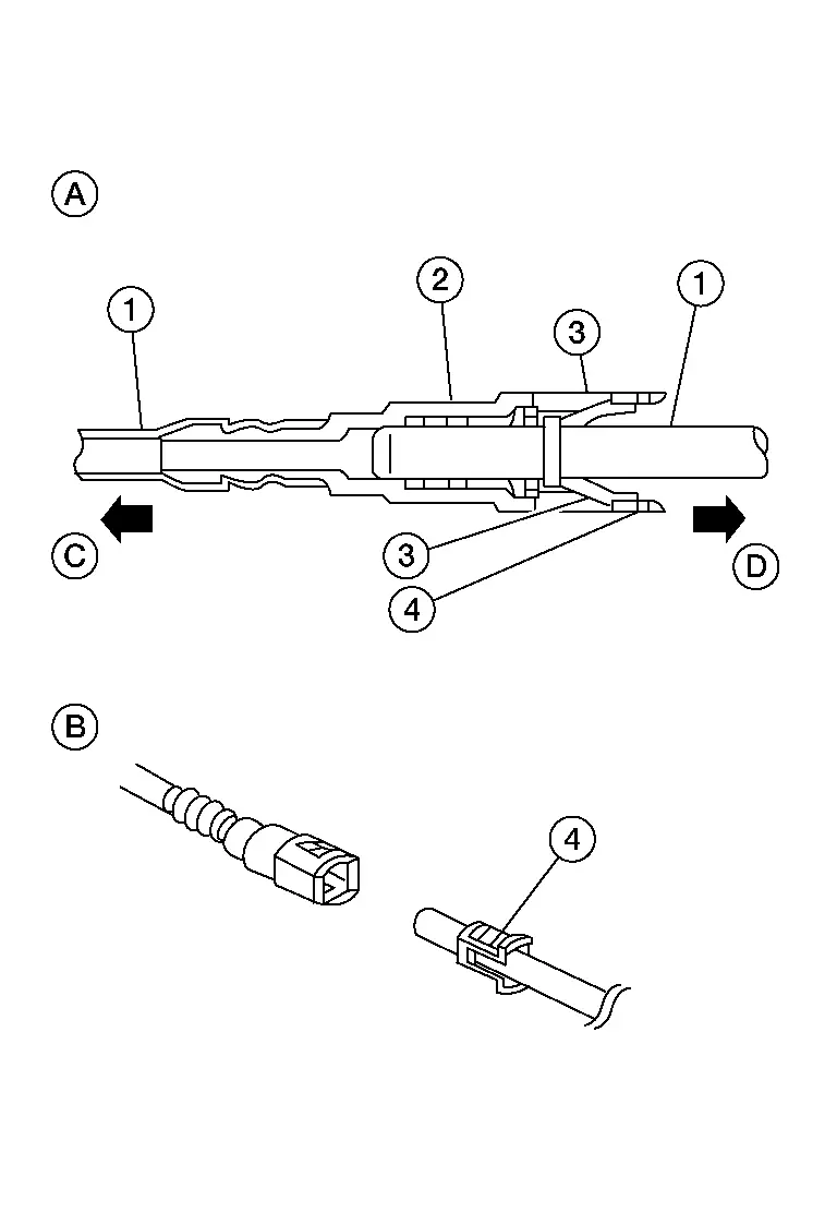
      (1) Resin tube

      (4) Retainer

      (A): Connector (cross section)

      (B): Disconnection

      (C): To under floor fuel line

      (D): To fuel tank

Installation of the remaining components is in the reverse order of removal.

INSPECTION AFTER INSTALLATION

Use the following procedure to check for fuel leaks.

With the ignition in the ON position (without starting the engine) to apply fuel pressure to the fuel system, then check the connections for fuel leaks.

Start engine, raise idle, and verify there are no fuel leaks at the fuel system connections.

Fuel Tank Nissan Pathfinder

Exploded View

For USA and Canada
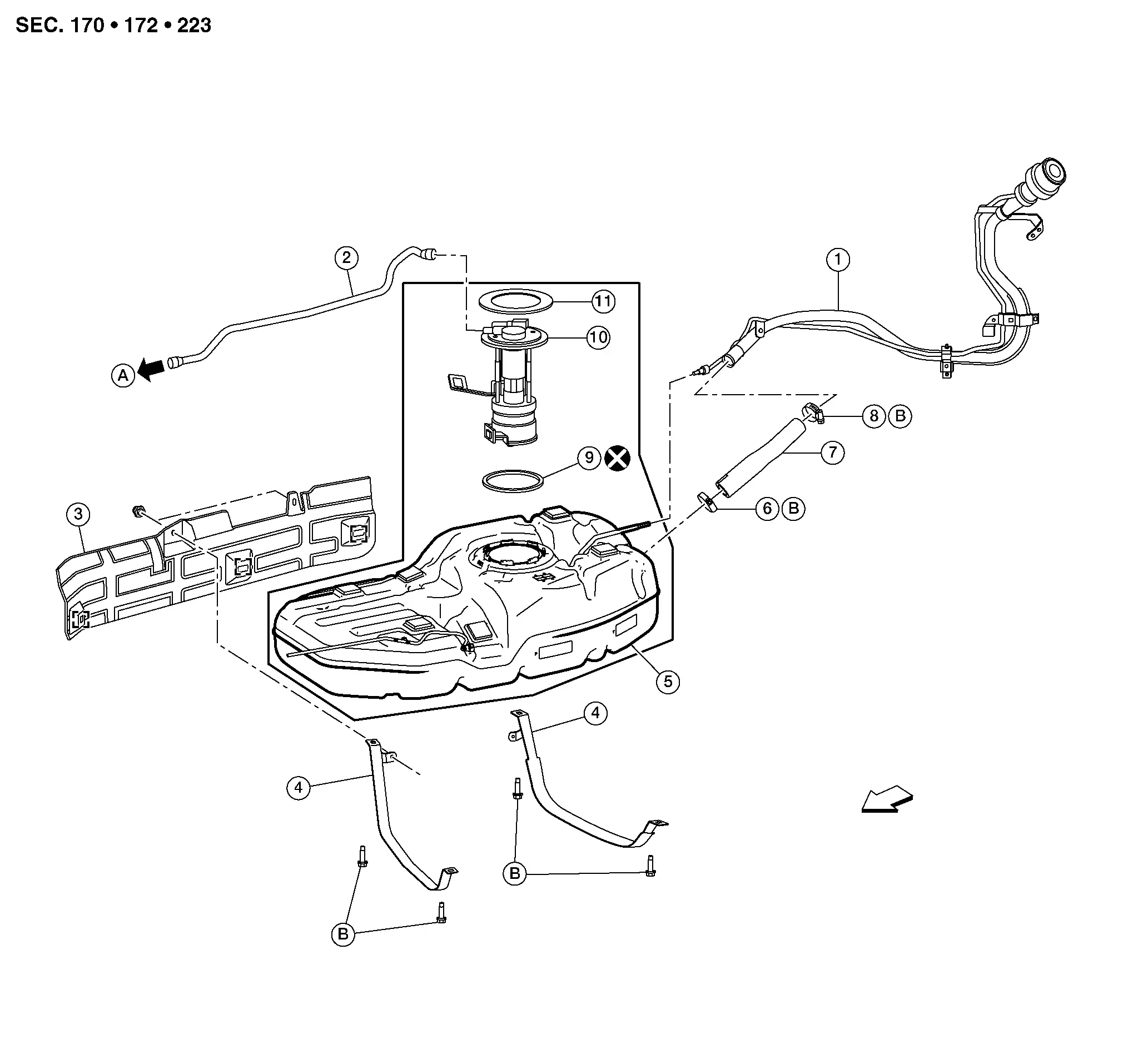
1. Fuel filler tube 2. EVAP vent tube 3. Fuel tank protector
4. Fuel tank mounting straps 5. Fuel tank assembly 6. Clamp
7. Fuel filler hose 8. Clamp 9. O-ring
10. Fuel level sensor unit, fuel filter and fuel pump assembly 11. Lock ring A. To EVAP canister. Refer to Exploded View.
B. Refer to Removal and Installation. Front

For Mexico

1. Fuel filler tube 2. EVAP vent tube 3. Fuel tank protector
4. Fuel tank mounting straps 5. Fuel tank assembly 6. Clamp
7. Fuel filler hose 8. Clamp 9. Clamp
10. Vent hose 11. O-ring 12. Fuel level sensor unit, fuel filter and fuel pump assembly
13. Lock ring A. To EVAP canister. Refer to Exploded View. B. Refer to Removal and Installation.
Front

Removal and Installation

REMOVAL

Using suitable tool open filler neck valve to release the pressure inside the fuel tank.

Check the fuel level with the Nissan Pathfinder vehicle on a level surface. If the fuel gauge indicates more than the level as shown (1/2 full), drain the fuel from the fuel tank until the fuel gauge indicates a level at or below as shown (1/2 full).
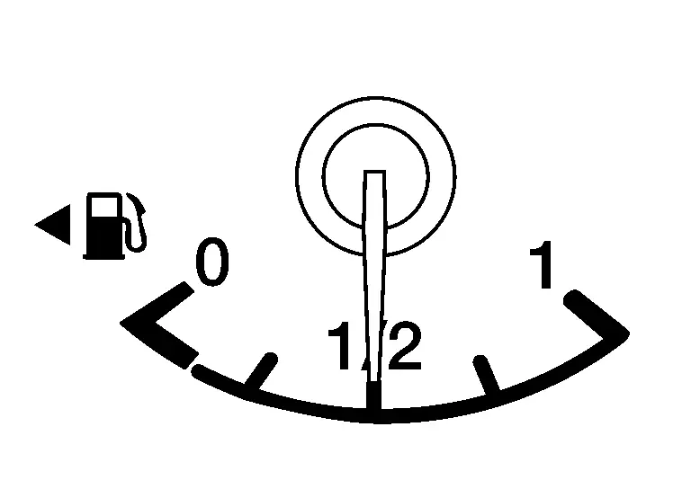
  • In case the fuel pump does not operate, use the following procedure.

Insert fuel tubing of less than 25 mm (0.98 in) diameter into the fuel filler tube through the fuel filler opening to drain fuel from the fuel filler tube. Disconnect the fuel filler hose from the fuel filler tube. Insert fuel tubing into the fuel tank through the fuel filler hose to drain fuel from the fuel tank.
  • As a guide, if the fuel tank is full, drain approximately 35 (9-1/4 US gal, 7-3/4 Imp gal) to reach 1/2 full or less.

Release fuel pressure from fuel line. Refer to Work Procedure.

Disconnect the battery negative terminal. Refer to Battery disconnect.

Remove second row seat (LH). Refer to Removal and Installation.

Position and secure the carpet to gain access to the fuel pump inspection hole cover.

Turn the four retainers (A) 90 degrees to disengage the clips and remove the fuel pump inspection hole cover.
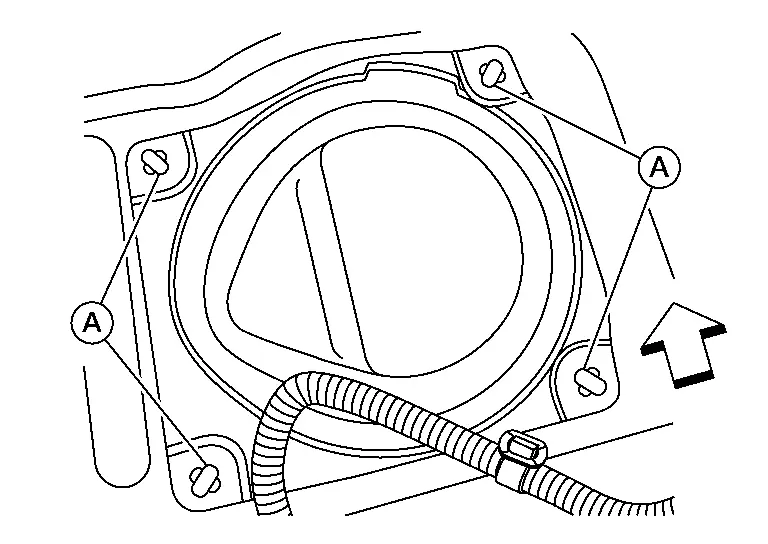
: Front

Disconnect the fuel level sensor unit, fuel filter, and fuel pump assembly harness connector (C) and the fuel feed hose connector (B) from the fuel level sensor unit, fuel filter, and fuel pump assembly.
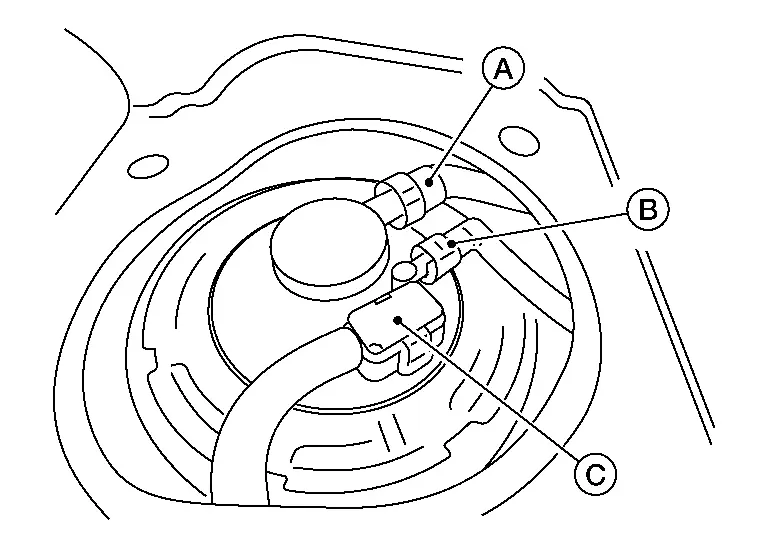
(A) : EVAP vent tube

  • Disconnect the quick connector as follows:
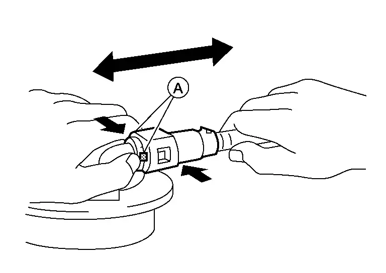
    • Hold the sides of the connector, push in tabs (A) and pull out the tube.

    • If the connector and the tube are stuck together, push and pull several times until they start to move. Then disconnect them by pulling.

Remove the floor under cover (LH). Refer to Removal and Installation.

Remove the EVAP vent tube from the EVAP canister.

Remove bolts and remove the rear exhaust tube heat shield.

Remove nuts securing rear propeller shaft assembly at center bearing. Refer to Exploded View.

Remove nuts and release metal clips and remove fuel tank protector from the fuel tank.

Remove the bolts and the outer reinforcement bar (if equipped).

Loosen clamp and remove the fuel filler hose from the fuel tank.

Disconnect the EVAP tube quick connector from the fuel filler tube (For USA and Canada models only).

Release clamp and remove EVAP hose from fuel filler tube (For Mexico models only).

Support the center part of the fuel tank using a suitable jack.

Remove fuel tank mounting strap bolts in reverse of the sequence shown while supporting the fuel tank with a suitable jack and remove fuel tank.
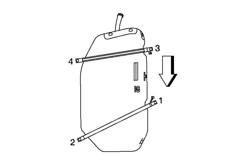
: Front

Lower suitable jack carefully to remove the fuel tank.

If replacing the fuel tank, remove the fuel level sensor unit, fuel filter and fuel pump assembly to transfer to the new fuel tank using the following procedure:Remove the lock ring using Tool.

Tool number

: — (NI-45722)

: KV101207S0 ( — )
Prior to removal, observe the alignment between the fuel level sensor unit, fuel filter, and fuel pump assembly tabs (A) and the matching marks (B) on the fuel tank as shown. This alignment is necessary for proper installation.

(C) : Retainer pawl

Raise the fuel level sensor unit, fuel filter, and fuel pump assembly high enough to gain access and disconnect the transfer tube connector (A).
Remove the fuel level sensor unit, fuel filter, and fuel pump assembly and O-ring. Discard the O-ring.

INSTALLATION

Installation is in the reverse order of removal.

  • Tighten the fuel tank mounting strap bolts to the specified torque in the sequence shown.
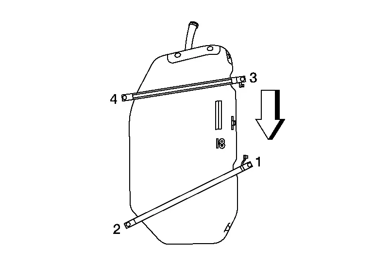
    Fuel tank mounting strap bolts : 40 N·m

    : Front
  • When installing fuel filler hose clamp (fuel tank side), the clamp should be positioned on paint mark located on fuel filler hose.

  • For USA and Canada models, tighten fuel filler hose clamp (fuel tank side) until bolt head is located on paint mark of band.

  • For Mexico models, tighten the fuel filler hose clamp (fuel tank side) to the specified torque.

    Clamp : 24 N·m
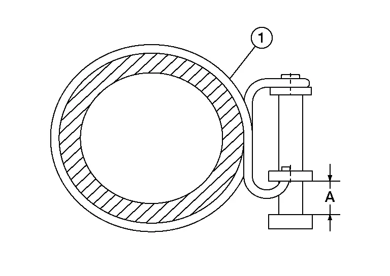
    Dimension (A) : 5 – 9 mm (0.20 – 0.35 in)

  • If fuel tank has been replaced, install the fuel level sensor unit, fuel filter, and fuel pump assembly using the following procedure:

    1. Connect the transfer tube (A) to the fuel level sensor unit, fuel filter, and fuel pump assembly.
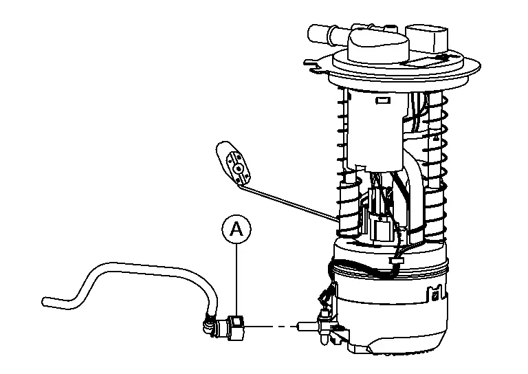
    2. Install a new O-ring on to fuel tank and install the fuel level sensor unit, fuel filter, and fuel pump assembly.

    3. Align the tabs (A) of the fuel level sensor unit, fuel filter, and fuel pump assembly to the matching marks (B) of the fuel tank for proper installation.
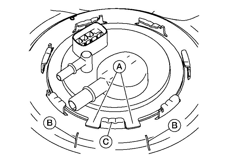
      (C) : Retainer pawl
    4. Install lock ring and turn clockwise using Tool.

      Tool number

      : — (NI-45722)

      : KV101207S0 ( — )
  • Connect the quick connector as follows:
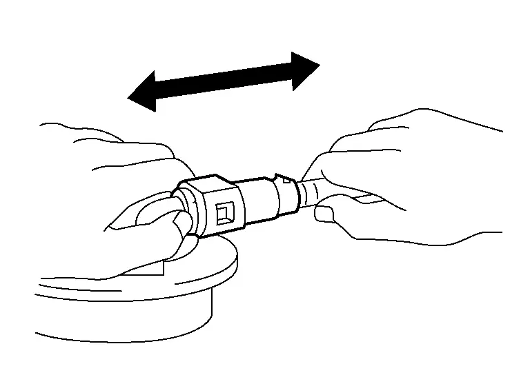
    1. Check the connection for damage or any foreign materials.

    2. Align the connector with the tube, then insert the connector straight into the tube until a click is heard.

  • After the tube is connected, make sure the connection is secure by performing the following checks:

    1. Pull the tube and the connector to make sure they are securely connected.

    2. Visually confirm that the two retainer tabs (3) are connected to the quick connector (2).

      (1): Resin tube

      (4): Retainer

      (A): Connection (cross-section)

      (B): Disconnection

      (C): To under floor fuel line

      (D): To fuel tank

INSPECTION AFTER INSTALLATION

Use the following procedure to check for fuel leaks.

With the ignition in the ON position (without starting the engine) to apply fuel pressure to the fuel system, then check the connections for fuel leaks.

Start engine, raise idle and verify there are no leaks at the fuel system connections.

Evap Canister Nissan Pathfinder R53

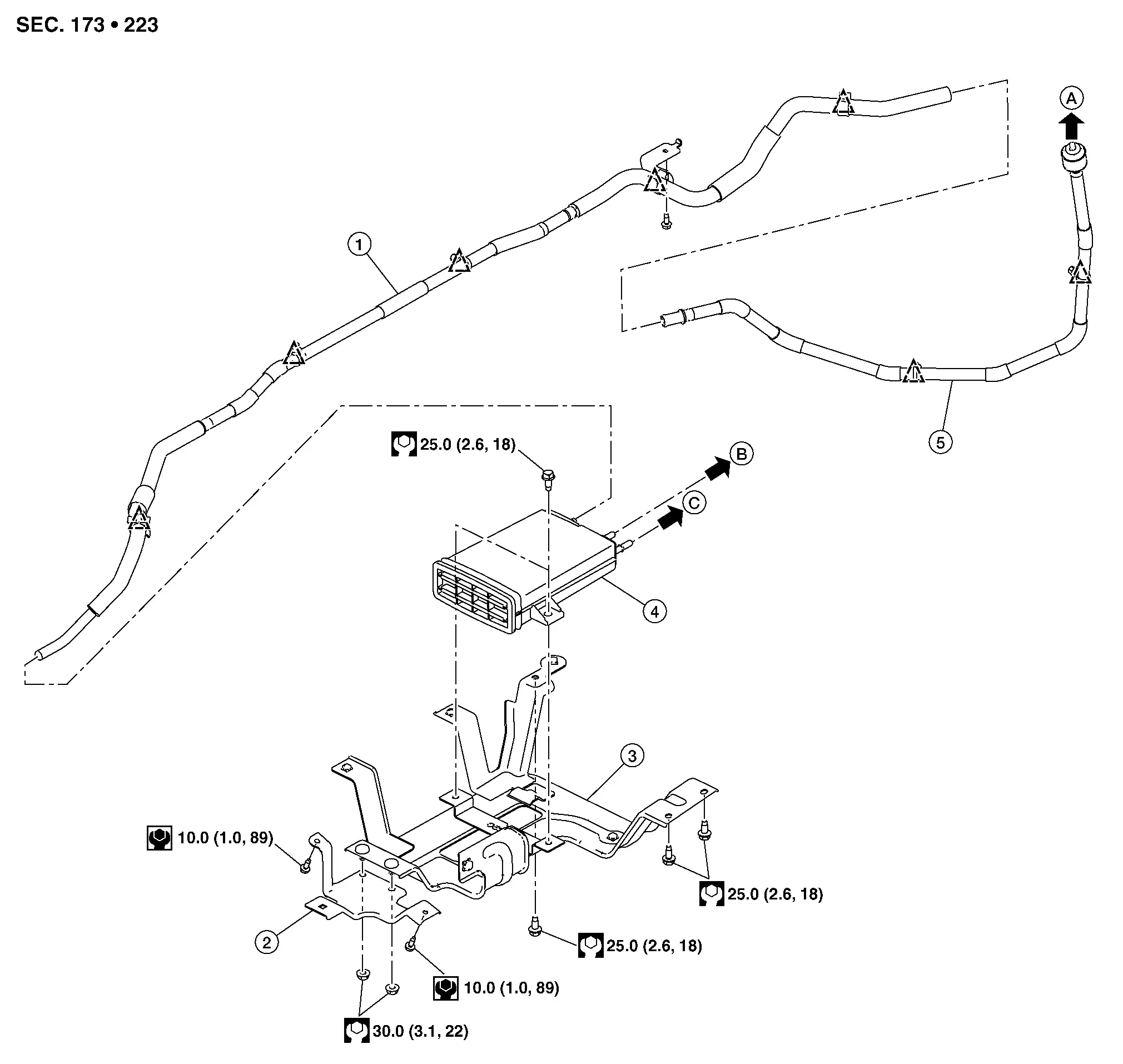
Exploded View

For USA and Canada
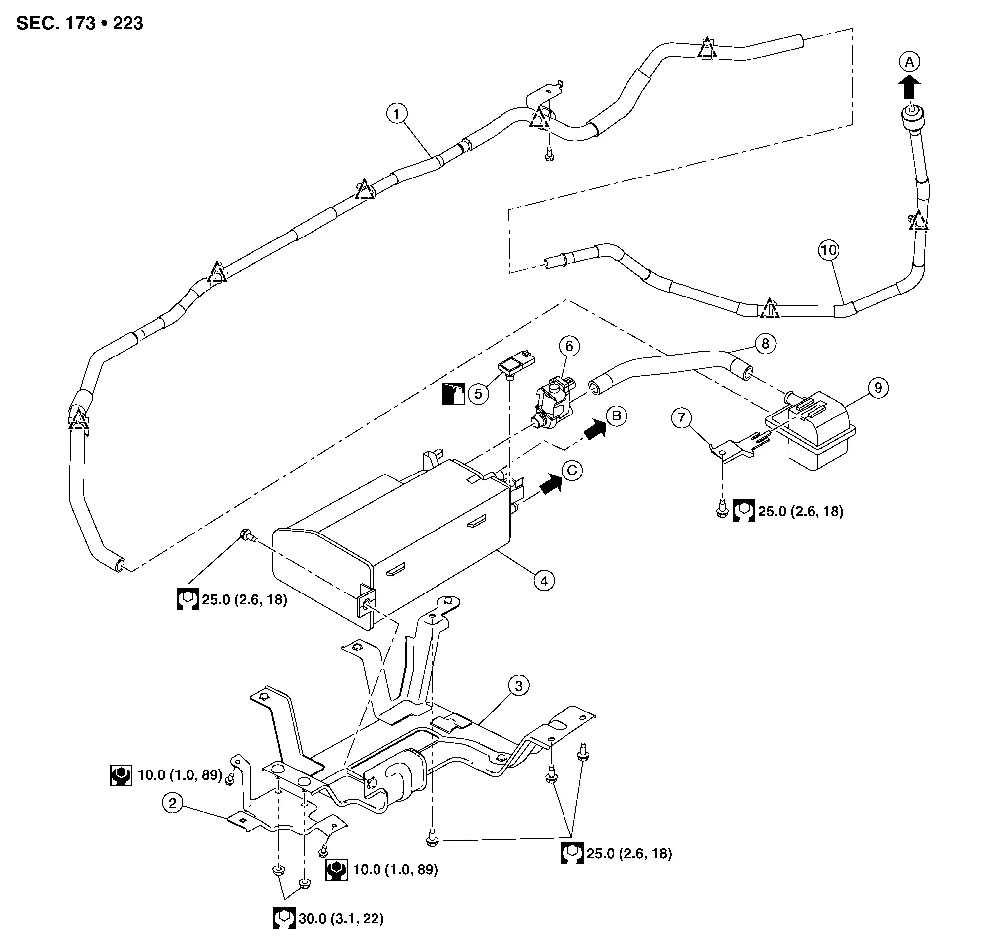
1. EVAP canister filter hose 2. EVAP canister bracket A 3. EVAP canister bracket B
4. EVAP canister 5. EVAP control system pressure sensor 6. EVAP canister vent control valve
7. EVAP canister vent control valve bracket 8. EVAP canister vent control valve hose 9. EVAP canister filter
10. EVAP canister filter hose A. To fuel filler tube. Refer to Exploded View. B. To EVAP vent tube. Refer to Exploded View.
C. To EVAP vacuum delay valve. Refer to Exploded View. Clip

For Mexico

1. EVAP canister hose 2. EVAP canister bracket A 3. EVAP canister bracket B
4. EVAP canister 5. EVAP canister hose A. To fuel filler tube. Refer to Exploded View.
B. To EVAP vent tube. Refer to Exploded View. C. To EVAP vacuum delay valve. Refer to Exploded View. Clip

Removal and Installation

For USA and Canada

REMOVAL

Remove the floor under cover (LH). Refer to Removal and Installation.

Disconnect the harness connectors from EVAP canister control pressure sensor and the EVAP canister vent control valve.

Remove the EVAP canister purge hose, the EVAP vent tube and the EVAP canister vent control valve hose.

Remove nuts securing EVAP canister bracket A to EVAP canister bracket B.

Remove EVAP canister bracket bolts and remove EVAP canister bracket and EVAP canister.

Remove bolt securing EVAP canister to EVAP canister bracket and remove EVAP canister.

Remove the EVAP canister vent control valve and EVAP canister control system pressure sensor from EVAP canister (if necessary).

INSTALLATION

Installation is in the reverse order of removal.

For Mexico

REMOVAL

Remove the floor under cover (LH). Refer to Removal and Installation.

Remove the EVAP canister hoses from the EVAP canister.

Remove nuts securing EVAP canister bracket A to EVAP canister bracket B.

Remove EVAP canister bracket bolts and remove EVAP canister bracket and EVAP canister.

Remove bolt securing EVAP canister to EVAP canister bracket and remove EVAP canister.

INSTALLATION

Installation is in the reverse order of removal.

Inspection

Check EVAP canister as follows:

Block port (A).

Blow air into port (B) and check that it flows freely out of port (C).

Release blocked port (A).

Apply vacuum pressure to port (A) and check that vacuum pressure exists at the ports (B) and (C).

Block port (B) and (A).

Apply pressure to port (C) and check that there is no leakage.

Evap Canister Filter Nissan Pathfinder 2026

Exploded View
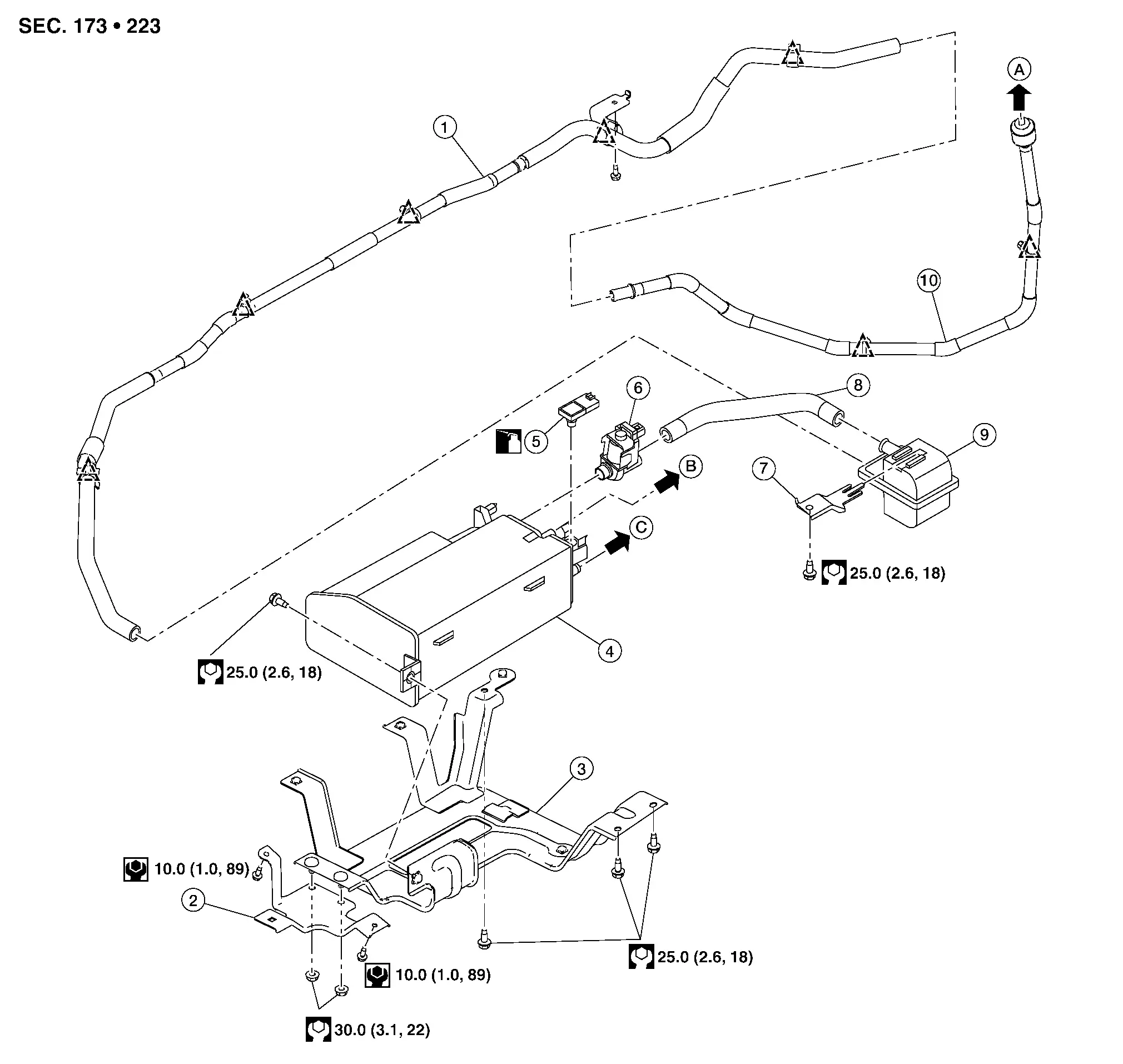
1. EVAP canister filter hose 2. EVAP canister bracket A 3. EVAP canister bracket B
4. EVAP canister 5. EVAP control system pressure sensor 6. EVAP canister vent control valve
7. EVAP canister vent control valve bracket 8. EVAP canister vent control valve hose 9. EVAP canister filter
10. EVAP canister filter hose A. To fuel filler tube. Refer to Exploded View. B. To EVAP vent tube. Refer to Exploded View.
C. To EVAP vacuum delay valve. Refer to Exploded View. Clip

Removal and Installation

REMOVAL

Remove the floor under cover (LH). Refer to Removal and Installation.

Remove EVAP canister vent control valve hose from EVAP canister filter.

Remove EVAP canister filter hose from EVAP canister filter.

Remove the bolt and remove the EVAP canister filter and EVAP canister filter bracket.

Remove the EVAP canister filter from the EVAP canister filter bracket (if necessary).

INSTALLATION

Installation is in the reverse order of removal.

Evap Canister Vent Control Valve Nissan Pathfinder Fifth generation

Exploded View
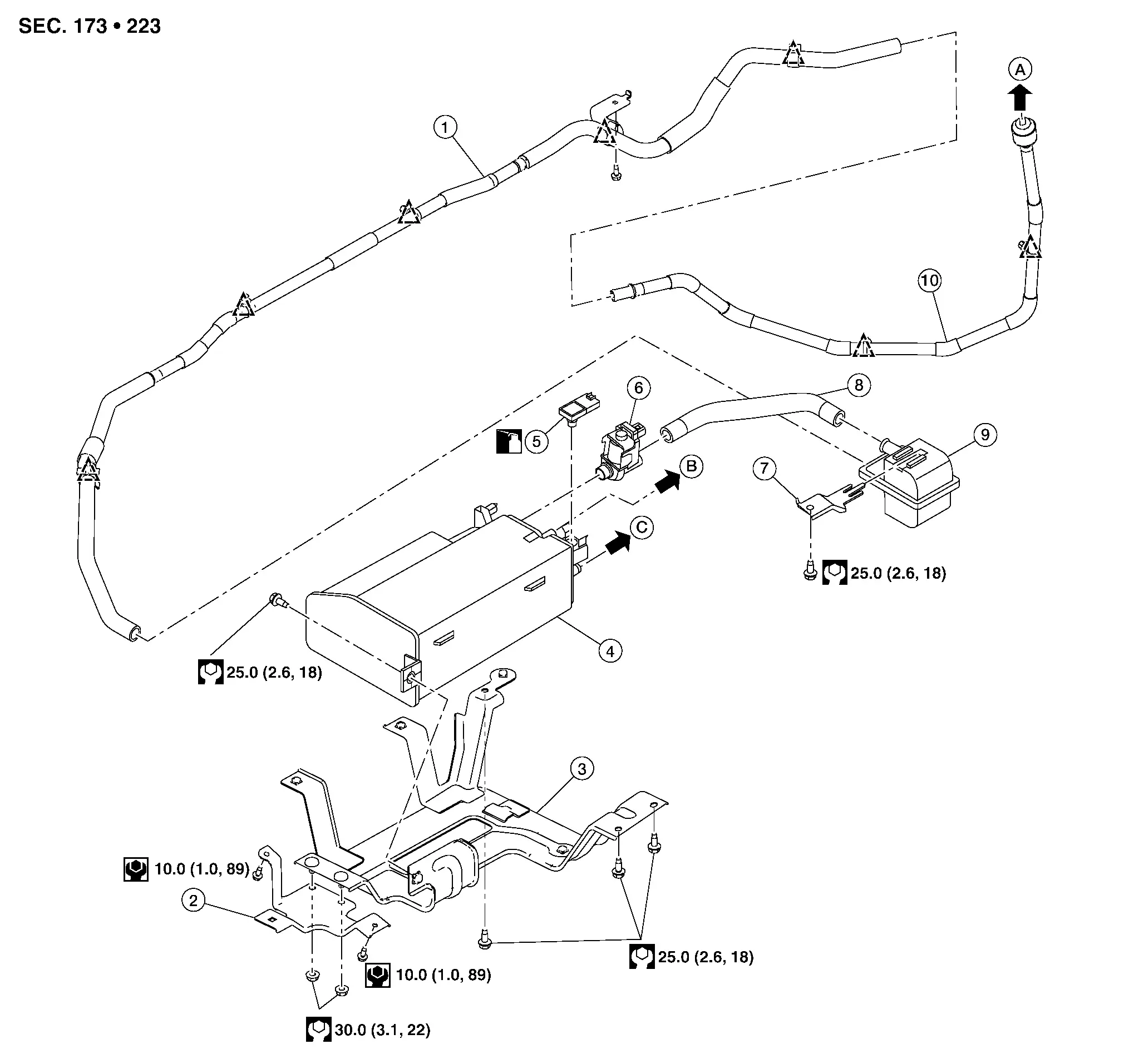
1. EVAP canister filter hose 2. EVAP canister bracket A 3. EVAP canister bracket B
4. EVAP canister 5. EVAP control system pressure sensor 6. EVAP canister vent control valve
7. EVAP canister vent control valve bracket 8. EVAP canister vent control valve hose 9. EVAP canister filter
10. EVAP canister filter hose A. To fuel filler tube. Refer to Exploded View. B. To EVAP vent tube. Refer to Exploded View.
C. To EVAP vacuum delay valve. Refer to Exploded View. Clip

Removal and Installation

REMOVAL

Remove the floor under cover (LH). Refer to Removal and Installation.

Remove EVAP canister vent control valve hose from EVAP canister vent control valve.

Disconnect the harness connector from EVAP canister vent control valve.

Turn EVAP canister vent control valve (1) counterclockwise.
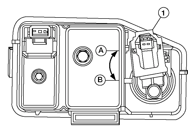
(A) : Lock
(B) : Unlock

Remove the EVAP canister vent control valve and O-ring.

INSTALLATION

Installation is in the reverse order of removal.

Evap Control System Pressure Sensor Nissan Pathfinder 2026

Exploded View

1. EVAP canister filter hose 2. EVAP canister bracket A 3. EVAP canister bracket B
4. EVAP canister 5. EVAP control system pressure sensor 6. EVAP canister vent control valve
7. EVAP canister vent control valve bracket 8. EVAP canister vent control valve hose 9. EVAP canister filter
10. EVAP canister filter hose A. To fuel filler tube. Refer to Exploded View. B. To EVAP vent tube. Refer to Exploded View.
C. To EVAP vacuum delay valve. Refer to Exploded View. Clip

Removal and Installation

REMOVAL

Remove the floor under cover (LH). Refer to Removal and Installation.

Disconnect the harness connector from EVAP canister control pressure sensor.

Remove EVAP canister control pressure sensor and O-ring.

INSTALLATION

Installation is in the reverse order of removal.

Evap Canister Volume Control Solenoid Valve Nissan Pathfinder 2022

Exploded View

1. EVAP canister purge volume control solenoid valve 2. Clamp 3. EVAP hose A
4. EVAP hose B 5. Clamp 6. EVAP vacuum delay valve
A. To intake manifold fitting. Refer to Exploded View. B. To EVAP canister. Refer to Exploded View.

Removal and Installation

REMOVAL

Remove engine cover. Refer to Removal and Installation.

Disconnect harness connector from EVAP canister purge volume control solenoid valve.

Release clamps and remove EVAP hose A and EVAP hose B from EVAP canister purge volume control solenoid valve.

Remove nut then remove EVAP canister purge volume control solenoid valve.

INSTALLATION

Installation is in the reverse order of removal.