Seat - System

In this manual: Seat - System
General Information — 8Engine :: Engine Mechanical — 19Engine Lubrication System - Precautions. Preparation — 1Engine Lubrication System - Lubrication System (System Description). Engine Oil Pressure (Basic Inspection). Service Data and Specifications (SDS) — 1Engine Cooling System - Precautions. Preparation. Service Data and Specifications (SDS) — 1Engine Cooling System - Engine Coolant — 1Engine Control System - System Description — 1System Description - Component Parts ++ — 1System Description - System ++ — 1Engine Control System - Ecu Diagnosis Information — 1Ecu Diagnosis Information - Ecm ++ — 1Engine Control System - Basic Inspection — 1Basic Inspection - Diagnosis and Repair Workflow ++ — 1Basic Inspection - Basic Inspection ++ — 1Basic Inspection - Additional Service When Replacing Ecm ++ — 1Basic Inspection - Fuel Pressure Check ++ — 1Basic Inspection - How to Set Srt Code ++ — 1Basic Inspection - How to Erase Permanent Dtc ++ — 1Engine Control System - Dtc/circuit Diagnosis — 1Engine Control System - Symptom Diagnosis — 1Engine Control System - Periodic Maintenance — 1Engine Control System - Removal and Installation — 1Fuel System - Precautions. Preparation. Service Data and Specifications (SDS) — 1Fuel System - Fuel System (Periodic Maintenance). Fuel Level Sensor Unit (Disassembly and Assembly) — 1Exhaust System - Precautions. Preparation — 1Exhaust System - Exhaust System (Periodic Maintenance). Exhaust System (Removal and Installation) — 1Starting System - Precautions. Preparation. Starter Motor (Service Data and Specifications (sds)) — 1Starting System - Diagnosis and Repair Work Flow — 1Starting System - Starting System (Symptom Diagnosis). Starter Motor (Removal and Installation) — 1Accelerator Control System - Precautions. Service Data and Specifications (SDS) — 1Accelerator Control System - Accelerator Pedal Assembly — 1Transmission & Driveline :: Transaxle & Transmission — 21Driveline - System Description — 1Transfer: Ty92b - Ecu Diagnosis Information. Awd Control Unit ++ — 1Driveline - Basic Inspection — 1Driveline - Dtc/circuit Diagnosis — 1Driveline - Symptom Diagnosis — 1Driveline - Removal and Installation — 1Transfer: Ty92b - Unit Removal and Installation. Transfer Assembly ++ — 1Driveline - Unit Disassembly and Assembly — 1Driveline - Basic Inspection — 1Driveline - Removal and Installation — 1Driveline - Unit Disassembly and Assembly — 1Front Axle - Precautions. Preparation — 1Front Axle - Noise, Vibration and Harshness (nvh) Troubleshooting (Symptom Diagnosis). Service Data and Specifications (SDS) — 1Front Axle - Front Drive Shaft Boot — 1Front Axle - Front Drive Shaft — 1Rear Axle - Precautions. Preparation. Service Data and Specifications (SDS) — 1Rear Axle - Noise, Vibration and Harshness (nvh) Troubleshooting — 1Rear Axle - Rear Drive Shaft — 1Suspension :: Front Suspension — 7Rear Suspension - Precautions. Preparation — 1Rear Suspension - Noise, Vibration and Harshness (nvh) Troubleshooting (Symptom Diagnosis). Service Data and Specifications (SDS) — 1Rear Suspension - Rear Suspension Assembly — 1Road Wheels & Tires - Precautions — 1Road Wheels & Tires - Preparation. Bcm (Ecu Diagnosis Information). Service Data and Specifications (SDS) — 1Road Wheels & Tires - System — 1Brakes :: Brake System — 9Parking Brake System - Precautions. Preparation — 1Parking Brake System - System — 1Vdc/tcs/abs - Precautions ++ — 1Brake Control System - System Description — 1System Description - Component Parts ++ — 1System Description - System ++ — 1Brake Control System - Basic Inspection — 1Brake Control System - Symptom Diagnosis — 1Brake Control System - Removal and Installation — 1Brake Control System - System Description — 1Brake Control System - Dtc/circuit Diagnosis — 1Brake Control System - Removal and Installation — 1Brake Control System - System Description — 1Brake Control System - Basic Inspection — 1Brake Control System - Symptom Diagnosis — 1Brake Control System - System Description — 1Brake Control System - Basic Inspection — 1Brake Control System - Symptom Diagnosis — 1Steering :: Steering System — 9Steering Control System - Precautions — 1Steering Control System - System — 1Steering Control System - Eps Control Unit (Ecu Diagnosis Information. Removal and Installation) — 1Restraints :: Seat Belt — 7Srs Air Bag - Precautions. Preparation — 1Srs Air Bag - Collision Diagnosis — 1Srs Air Bag - Occupant Classification System — 1Srs Air Bag Control System - Precautions — 1Srs Air Bag Control System - System — 1Srs Air Bag Control System - Diagnosis Sensor Unit — 1Srs Air Bag Control System - Inspection and Adjustment — 1Ventilation, Heater & Air Conditioner :: Ventilation System — 6Heater & Air Conditioning System - Precautions — 1Heater & Air Conditioning System - Preparation — 1Heater & Air Conditioning System - Component Parts — 1Heater & Air Conditioning System - Diagnosis and Repair Work Flow — 1Heater & Air Conditioning System - Compressor — 1Heater & Air Conditioning System - Cooler Pipe and Hose — 1Heater & Air Conditioning System - Condenser. Condenser — 1Heater & Air Conditioning System - Heating and Cooling Unit Assembly — 1Heater & Air Conditioning System - Service Data and Specifications (SDS) — 1Heater & Air Conditioning Control System - System Description — 1System Description - Component Parts ++ — 1System Description - System ++ — 1System Description - Operation ++ — 1Heater & Air Conditioning Control System - Ecu Diagnosis Information — 1Heater & Air Conditioning Control System - Basic Inspection — 1Heater & Air Conditioning Control System - Dtc/circuit Diagnosis — 1Heater & Air Conditioning Control System - Symptom Diagnosis — 1Heater & Air Conditioning Control System - Removal and Installation — 1Body Interior :: Interior — 8Instrument Panel - Precautions. Preparation. Clip List — 1Instrument Panel - Squeak and Rattle Trouble Diagnoses — 1Instrument Panel - Cluster Lid C — 1Seat - Precautions — 1Seat - Preparation. Clip List — 1Seat - Component Parts — 1Seat - System — 1Seat - Diagnosis and Repair Work Flow — 1Seat - Front Seat — 1Seat - Second Row Seats — 1Seat - Third Row Seats — 1Seat - Front Seat — 1Seat - Second Row Seat — 1Seat - Third Row Seat — 1Automatic Drive Positioner - Precautions. Preparation — 1Automatic Drive Positioner - System — 1Automatic Drive Positioner - Diagnosis and Repair Work Flow — 1Automatic Drive Positioner - Inspection and Adjustment — 1Body Exterior, Doors, Roof & Vehicle Security :: Door & Lock — 38Security Control System - Precautions — 1Security Control System - System — 1Security Control System - Ecm, Bcm, Intelligent Key Unit, Ipdm E/r — 1Security Control System - Vehicle Security System Cannot Be Set — 1Glass & Window System - Precautions. Preparation — 1Glass & Window System - Squeak and Rattle Trouble Diagnoses — 1Power Window Control System - Precautions. Preparation — 1Power Window Control System - Power Supply and Ground Circuit — 1Power Window Control System - Power Window Motor Circuit — 1Power Window Control System - Front Power Window Rh Alone Does Not Operate — 1Power Window Control System - Rear Lh Side Power Window Alone Does Not Operate — 1Power Window Control System - Rear Rh Side Power Window Alone Does Not Operate — 1Roof - Precautions. Preparation — 1Roof - Power Supply and Ground Circuit — 1Roof - Moonroof Switch Assembly — 1Roof - Lin Communication Circuit — 1Roof - Auto Operation Does Not Operate — 1Roof - Anti-Pinch Function Does Not Operate — 1Exterior - Precautions. Preparation. Clip List (Preparation) — 1Exterior - Squeak and Rattle Trouble Diagnoses — 1Exterior - Fender Protector — 1Exterior - Over Fender — 1Exterior - Under Cover — 1Exterior - Roof Side Rail — 1Body Repair - Service Information — 1Service Information - Sheet Metal Work ++ — 1Service Information - Body Welding and Precautions ++ — 1Service Information - Safety and Health ++ — 1Service Information - Repairing Procedures and Precautions ++ — 1Body Repair - Precaution — 1Body Repair - Preparation — 1Body Repair - Removal and Installation — 1Driver Controls :: Mirrors — 8Exterior Lighting System - System Description — 1System Description - Component Parts ++ — 1Exterior Lighting System - Basic Inspection — 1Exterior Lighting System - Dtc/circuit Diagnosis — 1Exterior Lighting System - Symptom Diagnosis — 1Exterior Lighting System - Periodic Maintenance — 1Exterior Lighting System - Removal and Installation — 1Interior Lighting System - Precautions. Preparation — 1Interior Lighting System - Component Parts. Interior Lighting System — 1Interior Lighting System - System — 1Interior Lighting System - Diagnosis and Repair Work Flow — 1Interior Lighting System - Interior Lighting System Symptoms (Symptom Diagnosis). Bcm (Ecu Diagnosis Information). Service Data and Specifications (SDS) — 1Interior Lighting System - Foot Lamp — 1Wiper & Washer - Precautions — 1Wiper & Washer - Preparation. Bcm, Ipdm E/r (Ecu Diagnosis Information). Service Data and Specifications (SDS) — 1Wiper & Washer - System — 1Wiper & Washer - Diagnosis and Repair Work Flow — 1Defogger - Precautions. Bcm, A/c Auto Amp. (Ecu Diagnosis Information) — 1Defogger - Diagnosis and Repair Work Flow — 1Horn - Precautions — 1Electrical & Power Control :: Power Outlet — 13Body Control System - Precautions. Preparation — 1Body Control System - Component Parts — 1Body Control System - System — 1Body Control System - Diagnosis System (bcm) — 1Body Control System - Bcm — 1Lan System - System Description — 1Lan System - System Description — 1Lan System - Dtc/circuit Diagnosis — 1Lan System - System Description — 1Lan System - Dtc/circuit Diagnosis — 1Power Control System - System Description — 1Power Control System - Basic Inspection — 1Power Control System - Dtc/circuit Diagnosis — 1Power Control System - System Description — 1Power Control System - Basic Inspection — 1Power Control System - Dtc/circuit Diagnosis — 1Power Control System - Removal and Installation — 1Charging System - Precautions. Preparation. Ecm, Ipdm E/r (Ecu Diagnosis Information) — 1Charging System - Diagnosis and Repair Work Flow — 1Charging System - Charging System (Symptom Diagnosis). Generator (Removal and Installation). Service Data and Specifications (SDS) — 1Power Supply, Ground & Circuit Elements - Precautions. Preparation. Service Data and Specifications (SDS) — 1Driver Information & Multimedia :: Meter, Warning Lamp & Indicator — 25Warning Chime System - Application Notice (How to Use This Manual). Precautions — 1Warning Chime System - System — 1Warning Chime System - Diagnosis System (combination Meter) — 1Warning Chime System - Bcm, Combination Meter (Ecu Diagnosis Information). Diagnosis and Repair Work Flow (Basic Inspection) — 1Sonar System - Precautions. Preparation — 1Sonar System - Sonar Control Unit — 1Dtc/circuit Diagnosis - B2720 Corner Sensor [rl] ++ — 1Audio, Visual & Navigation System - System Description — 1System Description - Component Parts ++ — 1System Description - System ++ — 1Audio, Visual & Navigation System - Ecu Diagnosis Information — 1Audio, Visual & Navigation System - Basic Inspection — 1Audio, Visual & Navigation System - Dtc/circuit Diagnosis — 1Dtc/circuit Diagnosis - Multi Av (av Control Unit) ++ — 1Audio, Visual & Navigation System - Symptom Diagnosis — 1Symptom Diagnosis - Multi Av System ++ — 1Audio, Visual & Navigation System - Removal and Installation — 1Audio, Visual & Navigation System - System Description — 1Audio, Visual & Navigation System - Ecu Diagnosis Information — 1Audio, Visual & Navigation System - Basic Inspection — 1Audio, Visual & Navigation System - Dtc/circuit Diagnosis — 1Audio, Visual & Navigation System - Symptom Diagnosis — 1Audio, Visual & Navigation System - Removal and Installation — 1Audio, Visual & Navigation System - System Description — 1Audio, Visual & Navigation System - Basic Inspection — 1Audio, Visual & Navigation System - Dtc/circuit Diagnosis — 1Audio, Visual & Navigation System - Symptom Diagnosis — 1Audio, Visual & Navigation System - Removal and Installation — 1Audio, Visual & Navigation System - System Description — 1Audio, Visual & Navigation System - Basic Inspection — 1Audio, Visual & Navigation System - Dtc/circuit Diagnosis — 1Audio, Visual & Navigation System - Symptom Diagnosis — 1Audio, Visual & Navigation System - Removal and Installation — 1Cruise Control & Driver Assistance :: Cruise Control System — 17Driver Assistance System - System Description — 1Driver Assistance System - Basic Inspection — 1Driver Assistance System - Dtc/circuit Diagnosis — 1Driver Assistance System - System Description — 1System Description - Component Parts ++ — 1System Description - System ++ — 1System Description - Operation ++ — 1System Description - Handling Precaution ++ — 1Driver Assistance System - Ecu Diagnosis Information — 1Driver Assistance System - Basic Inspection — 1Basic Inspection - Distance Sensor Alignment ++ — 1Basic Inspection - Camera Aiming Adjustment ++ — 1Basic Inspection - Action Test ++ — 1Driver Assistance System - Dtc/circuit Diagnosis — 1Dtc/circuit Diagnosis - Laser/radar (distance Sensor) ++ — 1Dtc/circuit Diagnosis - Lane Camera (front Camera Unit) ++ — 1Driver Assistance System - Symptom Diagnosis — 1Driver Assistance System - Removal and Installation — 1Driver Assistance System - System Description — 1System Description - System ++ — 1Driver Assistance System - Basic Inspection — 1Driver Assistance System - Dtc/circuit Diagnosis — 1Drive Mode System - Precautions — 1Drive Mode System - Component Parts. Drive Mode System — 1Drive Mode System - System — 1Drive Mode System - Diagnosis and Repair Work Flow — 1Drive Mode System - Drive Mode Select Switch Circuit — 1Maintenance - Precautions. Preparation — 1Maintenance - General Maintenance — 1Maintenance - Periodic Maintenance — 1Maintenance - Recommended Fluids and Lubricants — 1Maintenance - Engine Maintenance — 1Maintenance - Chassis and Body Maintenance — 1Engine Lubrication System - Periodic Maintenance — 1Engine Lubrication System - Removal and Installation — 1Engine Cooling System - System Description — 1Engine Cooling System - Removal and Installation — 1Engine Control System - Vq35dd — 1Fuel System - Removal and Installation — 1Starting System - System Description — 1Starting System - Dtc/circuit Diagnosis — 1Driveline - Transfer: Ty92b — 1Driveline - Rear Propeller Shaft: 3fcj-Cvj — 1Driveline - Rear Final Drive: R145 — 1Front Axle - Periodic Maintenance — 1Front Axle - Removal and Installation — 1Rear Axle - Periodic Maintenance — 1Rear Axle - Removal and Installation — 1Rear Suspension - Removal and Installation — 1Road Wheels & Tires - System Description — 1Road Wheels & Tires - Basic Inspection — 1Road Wheels & Tires - Dtc/circuit Diagnosis — 1Road Wheels & Tires - Symptom Diagnosis — 1Road Wheels & Tires - Periodic Maintenance — 1Road Wheels & Tires - Removal and Installation — 1Parking Brake System - System Description — 1Parking Brake System - Basic Inspection — 1Parking Brake System - Dtc/circuit Diagnosis — 1Parking Brake System - Symptom Diagnosis — 1Parking Brake System - Removal and Installation — 1Brake Control System - Vdc/tcs/abs — 1Brake Control System - Automatic Brake Hold — 1Brake Control System - Automatic Emergency Braking — 1Brake Control System - Rear Automatic Braking — 1Steering Control System - System Description — 1Steering Control System - Basic Inspection — 1Steering Control System - Dtc/circuit Diagnosis — 1Steering Control System - Symptom Diagnosis — 1Srs Air Bag - Removal and Installation — 1Srs Air Bag Control System - System Description — 1Srs Air Bag Control System - Basic Inspection — 1Srs Air Bag Control System - Symptom Diagnosis — 1Heater & Air Conditioning System - Symptom Diagnosis — 1Heater & Air Conditioning System - Periodic Maintenance — 1Heater & Air Conditioning Control System - Automatic Air Conditioning — 1Instrument Panel - Removal and Installation — 1Instrument Panel - Unit Disassembly and Assembly — 1Seat - Ecu Diagnosis Information — 1Seat - Dtc/circuit Diagnosis — 1Seat - Symptom Diagnosis — 1Automatic Drive Positioner - System Description — 1Automatic Drive Positioner - Ecu Diagnosis Information — 1Automatic Drive Positioner - Dtc/circuit Diagnosis — 1Automatic Drive Positioner - Symptom Diagnosis — 1Automatic Drive Positioner - Removal and Installation — 1Security Control System - System Description — 1Security Control System - Basic Inspection — 1Security Control System - Dtc/circuit Diagnosis — 1Security Control System - Symptom Diagnosis — 1Security Control System - Removal and Installation — 1Glass & Window System - Removal and Installation — 1Power Window Control System - System Description — 1Power Window Control System - Ecu Diagnosis Information — 1Power Window Control System - Basic Inspection — 1Power Window Control System - Dtc/circuit Diagnosis — 1Power Window Control System - Symptom Diagnosis — 1Power Window Control System - Removal and Installation — 1Roof - System Description — 1Roof - Ecu Diagnosis Information — 1Roof - Basic Inspection — 1Roof - Dtc/circuit Diagnosis — 1Roof - Symptom Diagnosis — 1Roof - Removal and Installation — 1Exterior - System Description — 1Exterior - Removal and Installation — 1Body Repair - Repair Information — 1Exterior Lighting System - Led Headlamp — 1Interior Lighting System - Dtc/circuit Diagnosis — 1Interior Lighting System - Removal and Installation — 1Wiper & Washer - System Description — 1Wiper & Washer - Dtc/circuit Diagnosis — 1Wiper & Washer - Symptom Diagnosis — 1Wiper & Washer - Removal and Installation — 1Defogger - System Description — 1Defogger - Dtc/circuit Diagnosis — 1Defogger - Symptom Diagnosis — 1Defogger - Removal and Installation — 1Horn - Removal and Installation — 1Body Control System - Basic Inspection — 1Body Control System - Dtc/circuit Diagnosis — 1Body Control System - Symptom Diagnosis — 1Body Control System - Removal and Installation — 1Lan System - Can Fundamental — 1Lan System - Can — 1Lan System - Can Gateway — 1Power Control System - Ipdm E/r — 1Power Control System - Power Distribution System — 1Charging System - System Description — 1Charging System - Dtc/circuit Diagnosis — 1Power Supply, Ground & Circuit Elements - System Description — 1Power Supply, Ground & Circuit Elements - Basic Inspection — 1Power Supply, Ground & Circuit Elements - Removal and Installation — 1Warning Chime System - System Description — 1Warning Chime System - Dtc/circuit Diagnosis — 1Warning Chime System - Symptom Diagnosis — 1Sonar System - System Description — 1Sonar System - Basic Inspection — 1Sonar System - Dtc/circuit Diagnosis — 1Sonar System - Symptom Diagnosis — 1Sonar System - Removal and Installation — 1Audio, Visual & Navigation System - Nissanconnect — 1Audio, Visual & Navigation System - Intelligent Around View Monitor System — 1Audio, Visual & Navigation System - Rear View Monitor System — 1Audio, Visual & Navigation System - Telematics System — 1Driver Assistance System - Adas Control Unit 2 — 1Driver Assistance System - Driver Assistance System — 1Driver Assistance System - Chassis Control — 1Drive Mode System - Removal and Installation — 1Dtc/circuit Diagnosis (C053c Wheel Speed Sensor ... U2141 Can Comm Circuit) — 1Dtc/circuit Diagnosis (P0011 Intake Valve Timing Control ... P0111 Iat Sensor) — 1Dtc/circuit Diagnosis (P0116 Engine Coolant Temperature Sensor ... P025b Fuel Pump Module a) — 1Dtc/circuit Diagnosis (P026b Injection Timing ... P0420 Three Way Catalyst Function) — 1Dtc/circuit Diagnosis (P0441 Evap Control System ... P0524 Engine Oil Pressure) — 1Dtc/circuit Diagnosis (P0532 A/c Refrigerant Pressure Sensor ... P064d Ecm) — 1Dtc/circuit Diagnosis (P06da Engine Oil Pressure Control Solenoid Valve ... P1217 Engine Over Temperature) — 1Dtc/circuit Diagnosis (P1220 Fuel Pump Control Module (fpcm) ... P1574 Ascd Vehicle Speed Sensor) — 1Dtc/circuit Diagnosis (P1575 Brake Switch ... P2101 Electric Throttle Control Function) — 1Dtc/circuit Diagnosis (P2118 Throttle Control Motor ... P34ac Electric Intake Valve Timing Control Actuator) — 1Dtc/circuit Diagnosis (Active Grille Shutter ... High Pressure Fuel Pump) — 1Dtc/circuit Diagnosis (Ignition Signal ... Variable Induction Air System) — 14012 C1040 Emergency Brake — 14013 C106a Wheel Sensor — 14014 C1078-55 Not Configuration — 14015 C10b4-98 Overheat — 14016 B1001 Lap Pre-Tensioner Lh — 14017 B0001 Driver Air Bag Module — 14018 B100e Knee Air Bag Module Rh — 14019 B142x Collision Detection — 1Dtc/circuit Diagnosis (B20c7-11 A/c Clutch ... B24a6-11 in-Vehicle Sensor) — 1Dtc/circuit Diagnosis (B24a6-15 in-Vehicle Sensor ... U2140-87 Can Comm Err (ecm)) — 1Dtc/circuit Diagnosis (C1f00-1c Control Unit ... C1f04-61 Brake Sw/stop Lamp Sw) — 1Dtc/circuit Diagnosis (C1f05-49 Front Camera Unit ... C1f70-87 Ethernet Circuit) — 1
~19min read
  • Power Seat System
  • 2 Way Lumbar Support System
  • Heated Seat System
  • Second Row Heated Seat System
  • Climate Controlled Seat System
  • Second Row Seat Power Walk in System

Power Seat System Nissan Pathfinder R53

System Description

Power seat can be operated regardless of the ignition switch status, because power is always supplied to the power seat switch.

SLIDING OPERATION

While operating the sliding switch located in the power seat switch, the sliding motor operates and makes forward and backward position adjustment of the seat possible.

RECLINING OPERATION

While operating the reclining switch located in the power seat switch, the reclining motor operates and makes forward and backward position adjustment of the seat back possible.

LIFTING OPERATION

While operating the lifting switch located in the power seat switch, the lifting motor (front) and lifting motor (rear) operate and make seat up and down position adjustment possible.

2 Way Lumbar Support System Nissan Pathfinder SUV

System Description

  • 2 way lumbar support can operate regardless of the ignition switch status, because power supply is always supplied to the lumbar support switch.

  • While operating the lumbar support switch, the lumbar support motor operates which makes forward and backward position adjustment of the seat back support possible.

Heated Seat System Nissan Pathfinder Fifth generation

System Description

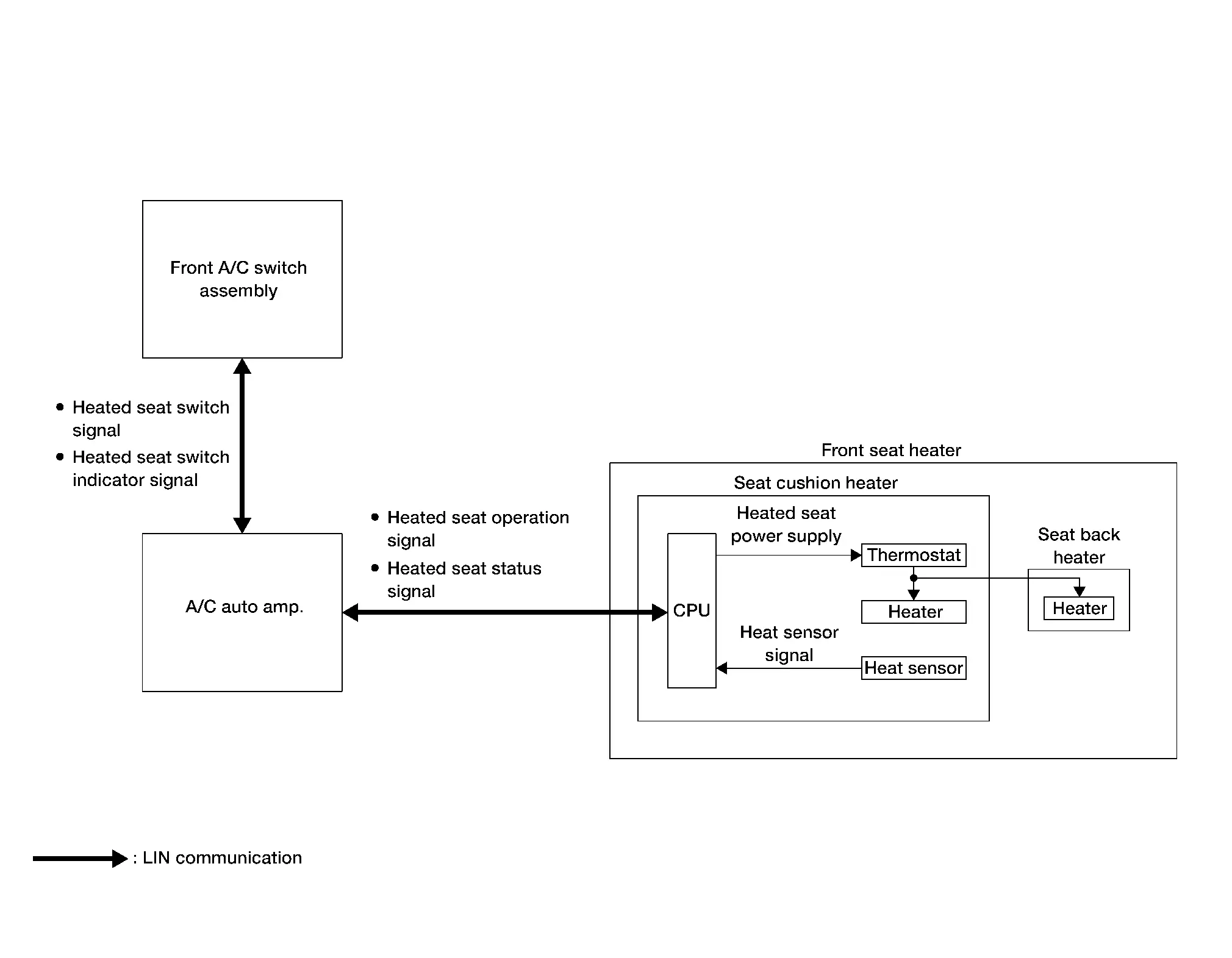
SYSTEM DIAGRAM
ComponentFunction
A/C auto amp. A/C auto amp. receives the switch operation signals transmitted from the front A/C switch assembly via LIN communication and transmits the switch operation signals to the front seat heater via LIN communication.
Front seat heater Refer to Front Seat Heater.
Front A/C switch assembly
  • Front heated seat switch is integrated in the front A/C switch assembly and is used to activate/deactivate the front seat heaters LH and RH, and set the temperature (Low, Mid, or High).

  • Front A/C switch assembly receives a switch indicator signal, it illuminates the indicator lamp on the front heated seat switch.

Signal transmission function list

Signal nameInputOutputDescription
Heated seat switch signal Front A/C switch assembly A/C auto amp. (LIN) Transmits the heated seat switch signal via LIN communication.
Heated seat switch indicator signal A/C auto amp. Front A/C switch assembly (LIN) Transmits the heated seat switch indicator signal via LIN communication.
Heated seat operation signal A/C auto amp. Front seat heater (LIN) Transmits the heated seat operation signal via LIN communication.
Heated seat status signal Front seat heater A/C auto amp. (LIN) Transmits the heated seat status signal via LIN communication.

DESCRIPTION

  • Heated seat system is activated by the front heated seat switch while engine is running.

  • The seat heater temperature can be adjusted at 3 levels (Low, Mid, High) respective to the heating function by operating the front heated seat switch.

  • The operation status of the heated seat system can be checked by checking the indicators of the front heated seat switch.

OPERATION DESCRIPTION

  • When the front heated seat switch is operated, the front A/C switch assembly recognizes switch operation.

  • The front A/C switch assembly transmits a switch operation signal to the A/C auto amp. via LIN communication.

  • When A/C auto amp. receives a switch operation signal, it operates the heated seat system.

  • The A/C auto amp. operates the heated seat system and simultaneously sends the switch indicator signal to the front A/C switch assembly via LIN communication.

  • When the front A/C switch assembly receives a switch indicator signal, it illuminates the indicator lamp on the front heated seat switch.

Heating Control

  • The seat cushion heater is integrated with a heat sensor that detects seat temperature. The heat sensor transmits the seat temperature as the heat sensor signal to the CPU integrated with the seat cushion heater.

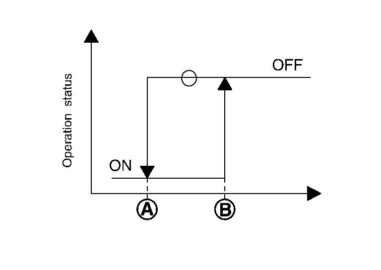
  • The CPU recognizes the seat temperature from heat sensor signal. It adjusts the seat temperature by stopping operation when the seat temperature reaches the operation stop temperature , and starting operation when the seat temperature reaches the operation start temperature .
Preset temperatureTemperature °F (°C)
Temperature at operation stopTemperature at operation start
Low 101.3 (38.5) 95.9 (35.5)
Mid 104.9 (40.5) 99.5 (37.5)
High 108.5 (42.5) 103.1 (39.5)

Fail-safe

  • Seat heater equips fail-safe function.

  • When a malfunction occurs in the systems shown below, seat heater performs fail-safe control:

Malfunction conditionFail-safeReset condition
Seat heater output circuit short or open Seat heater operation is suspended. Ignition switch OFF
Heat sensor circuit short or open Seat heater operation is suspended. Ignition switch OFF
The high temperature of the seat heater is detected by the heat sensor Seat heater operation is suspended. Ignition switch OFF
The thermostat integrated into the seat heater detects a malfunction Seat heater operation is suspended. Ignition switch OFF
The seat heater output circuit short to the ground (detected 800 times) All operations are suspended. ―
The CPU integrated into the seat cushion heater is hot All operations are suspended. Ignition switch OFF
The data that configures the software of the CPU integrated into the seat cushion heater is in an abnormal condition The program is initialized. Ignition switch ON
The power supplied to the seat heater is in an abnormal condition (less than 8.5 V, or 16.5 V or more) Seat heater operation is suspended. The power supply is normalized (10.5 V - 15.5 V or less)
An abnormal LIN communication has occurred Seat heater operation is suspended. The LIN communication is normalized

Second Row Heated Seat System Nissan Pathfinder SUV

System Description

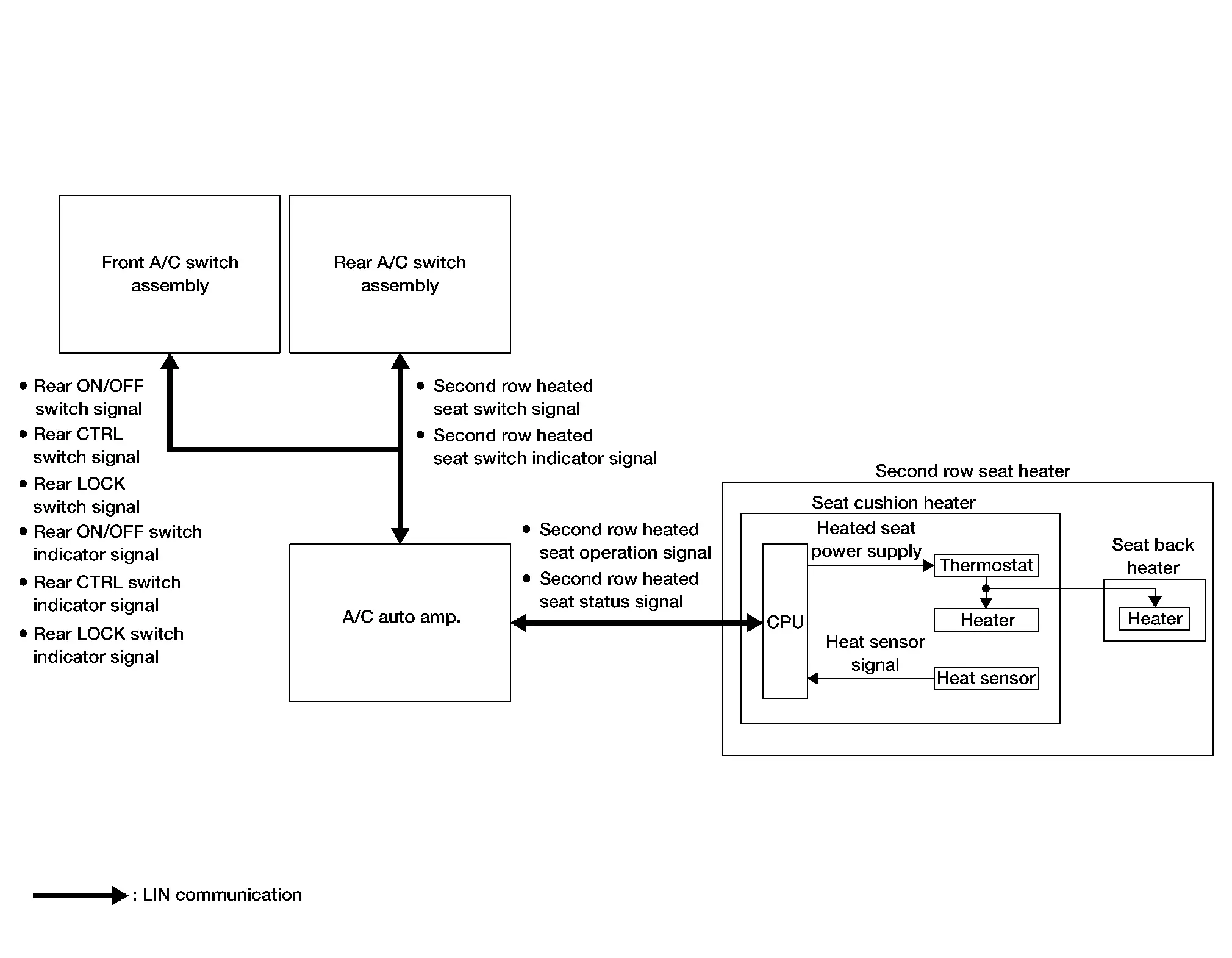
SYSTEM DIAGRAM
ComponentFunction
A/C auto amp. A/C auto amp. receives the switch operation signals transmitted from the front and rear A/C switch assemblies via LIN communication and transmits the switch operation signals to the second row seat heater via LIN communication.
Second row seat heater Refer to Second Row Seat Heater.
Front A/C switch assembly
  • Rear control switches are integrated in the front A/C switch assembly, and are used to turn ON/OFF, and to lock the rear A/C switch assembly.

  • Front A/C switch assembly receives a switch indicator signal, it illuminates the indicator lamp on the rear control switches.

Rear A/C switch assembly
  • Second row heated seat switch is integrated in the rear A/C switch assembly, and is used to activate/deactivate the second row seat heaters and set the temperature (Low, Mid, or High).

  • Rear A/C switch assembly receives a switch indicator signal, it illuminates the indicator lamp on the second row heated seat switch.

Signal transmission function list

Signal nameInputOutputDescription
Rear ON/OFF switch signal Front A/C switch assembly Rear A/C switch assembly (LIN) Transmits the rear ON/OFF switch signal via LIN communication.
Rear CTRL switch signal Front A/C switch assembly Rear A/C switch assembly (LIN) Transmits the rear CTRL switch signal via LIN communication.
Rear LOCK switch signal Front A/C switch assembly Rear A/C switch assembly (LIN) Transmits the rear LOCK switch signal via LIN communication.
Rear ON/OFF switch indicator signal Rear A/C switch assembly Front A/C switch assembly (LIN) Transmits the rear ON/OFF switch indicator signal via LIN communication.
Rear CTRL switch indicator signal Rear A/C switch assembly Front A/C switch assembly (LIN) Transmits the rear CTRL switch indicator signal via LIN communication.
Rear LOCK switch indicator signal Rear A/C switch assembly Front A/C switch assembly (LIN) Transmits the rear LOCK switch indicator signal via LIN communication.
Second row heated seat switch signal Rear A/C switch assembly A/C auto amp. (LIN) Transmits the second row heated seat switch signal via LIN communication.
Second row heated seat switch indicator signal A/C auto amp. Rear A/C switch assembly (LIN) Transmits the second row heated seat switch indicator signal via LIN communication.
Second row heated seat operation signal A/C auto amp Second row seat heater (LIN) Transmits the second row heated seat operation signal via LIN communication.
Second row heated seat status signal Second row seat heater A/C auto amp. (LIN) Transmits the second row heated seat status signal via LIN communication.

DESCRIPTION

  • Second row heated seat system is activated by the second row heated seat switch while the engine is running.

  • The seat heater temperature can be adjusted at 3 levels (Low, Mid, High) respective to the heating function by operating the second row heated seat switch.

  • The operation status of the second row heated seat system can be checked by checking the indicators of the second row heated seat switch.

OPERATION DESCRIPTION

  • When the second row heated seat switch is operated, the rear A/C switch assembly recognizes switch operation.

  • The rear A/C switch assembly transmits a switch operation signal to the A/C auto amp. via LIN communication.

  • When A/C auto amp. receives a switch operation signal, it operates the second row heated seat system.

  • The A/C auto amp. operates the second row heated seat system and simultaneously sends the switch indicator signal to the rear A/C switch assembly via LIN communication.

  • When the rear A/C switch assembly receives a switch indicator signal, it illuminates the indicator lamp on the second row heated seat switch.

Heating Control

  • The seat cushion heater is integrated with a heat sensor that detects the seat temperature. The heat sensor transmits the seat temperature as the heat sensor signal to the CPU integrated with the seat cushion heater.

  • The CPU recognizes the seat temperature from the heat sensor signal. It adjusts the seat temperature by stopping operation when the seat temperature reaches the operation stop temperature , and starting operation when the seat temperature reaches the operation start temperature .

Preset temperatureTemperature °F (°C)
Temperature at operation stopTemperature at operation start
Low 101.3 (38.5) 95.9 (35.5)
Mid 104.9 (40.5) 99.5 (37.5)
High 108.5 (42.5) 103.1 (39.5)

Fail-safe

  • Seat heater equips fail-safe function.

  • When a malfunction occurs in the systems shown below, seat heater performs fail-safe control:

Malfunction conditionFail-safeReset condition
Seat heater output circuit short or open Seat heater operation is suspended. Ignition switch OFF
Heat sensor circuit short or open Seat heater operation is suspended. Ignition switch OFF
The high temperature of the seat heater is detected by the heat sensor Seat heater operation is suspended. Ignition switch OFF
The thermostat integrated into the seat heater detects a malfunction Seat heater operation is suspended. Ignition switch OFF
The seat heater output circuit short to ground (detected 800 times) All operations are suspended. ―
The CPU integrated into the seat cushion heater is hot All operations are suspended. Ignition switch OFF
The data that configures the software of the CPU integrated into the seat cushion heater is in an abnormal condition The program is initialized. Ignition switch ON
The power supplied to the seat heater is in an abnormal condition (less than 8.5 V, or 16.5 V or more) Seat heater operation is suspended. The power supply is normalized (10.5 V - 15.5 V or less)
An abnormal LIN communication has occurred Seat heater operation is suspended. The LIN communication is normalized

Climate Controlled Seat System Nissan Pathfinder

System Description

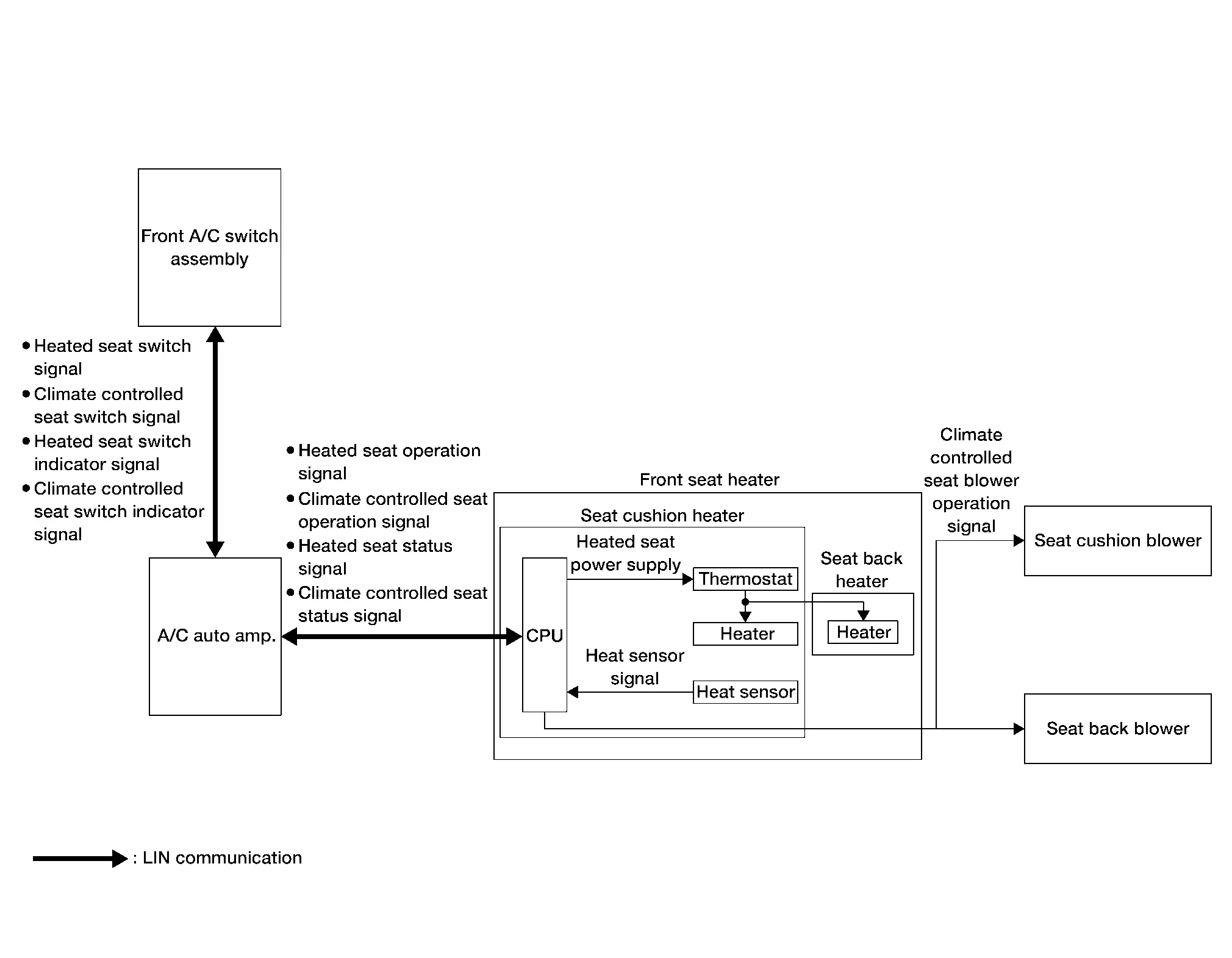
SYSTEM DIAGRAM
ComponentFunction
A/C auto amp. A/C auto amp. receives the switch operation signals transmitted from the front A/C switch assembly via LIN communication and transmits the switch operation signals to the front seat heater via LIN communication.
Front seat heater Refer to Front Seat Heater.
Seat cushion blower Refer to Seat Cushion Blower.
Seat back blower Refer to Seat Back Blower.
Front A/C switch assembly
  • Front heated seat switch is integrated in the front A/C switch assembly and is used to activate/deactivate the front seat heaters LH and RH, and set the temperature (Low, Mid, or High).

  • Front A/C switch assembly receives a switch indicator signal, it illuminates the indicator lamp on the front heated seat switch.

  • Climate controlled seat switch is integrated in the front A/C switch assembly and is used to activate/deactivate the front seat LH and RH seat cushion and seat back blowers, and set the temperature (Low, Mid, or High).

  • Front A/C switch assembly receives a switch indicator signal, it illuminates the indicator lamp on the climate controlled seat switch.

Signal transmission function list

Signal nameInputOutputDescription
Heated seat switch signal Front A/C switch assembly A/C auto amp. (LIN) Transmits the heated seat switch signal via LIN communication.
Climate controlled seat switch signal Front A/C switch assembly A/C auto amp. (LIN) Transmits the climate controlled seat switch signal via LIN communication.
Heated seat switch indicator signal A/C auto amp. Front A/C switch assembly (LIN) Transmits the heated seat switch indicator signal via LIN communication.
Climate controlled seat switch indicator signal A/C auto amp. (LIN) Front A/C switch assembly Transmits the climate controlled seat switch indicator signal via LIN communication.
Heated seat operation signal A/C auto amp. Front seat heater (LIN) Transmits the heated seat operation signal via LIN communication.
Climate controlled seat operation signal A/C auto amp. Front seat heater (LIN) Transmits the climate controlled seat operation signal via LIN communication.
Heated seat status signal Front seat heater A/C auto amp. (LIN) Transmits the heated seat status signal via LIN communication.
Climate controlled seat status signal Front seat heater A/C auto amp. (LIN) Transmits the climate controlled seat seat status signal via LIN communication.

HEATED SEAT DESCRIPTION

  • Heated seat system is activated by the front heated seat switch while the engine is running.

  • The seat heater temperature can be adjusted at 3 levels (Low, Mid, High) respective to the heating function by operating the front heated seat switch.

  • The operation status of the heated seat system can be checked by checking the indicators of the front heated seat switch.

HEATED SEAT OPERATION DESCRIPTION

  • When the front heated seat switch is operated, the front A/C switch assembly recognizes switch operation.

  • The front A/C switch assembly transmits a switch operation signal to the A/C auto amp. via LIN communication.

  • When A/C auto amp. receives a switch operation signal, it operates the heated seat system.

  • The A/C auto amp. operates the heated seat system and simultaneously sends the switch indicator signal to the front A/C switch assembly via LIN communication.

  • When the front A/C switch assembly receives a switch indicator signal, it illuminates the indicator lamp on the front heated seat switch.

Heating Control

  • The seat cushion heater is integrated with a heat sensor that detects seat temperature. The heat sensor transmits the seat temperature as the heat sensor signal to the CPU integrated with the seat cushion heater.

  • The CPU recognizes the seat temperature from the heat sensor signal. It adjusts the seat temperature by stopping operation when the seat temperature reaches the operation stop temperature , and starting operation when the seat temperature reaches the operation start temperature .
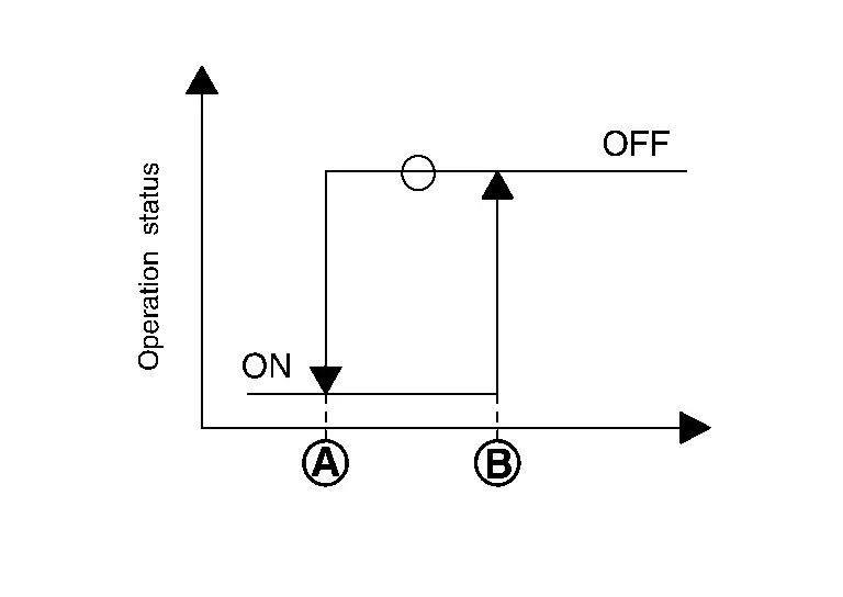
Preset temperatureTemperature °F (°C)
Temperature at operation stopTemperature at operation start
Low 101.3 (38.5) 95.9 (35.5)
Mid 104.9 (40.5) 99.5 (37.5)
High 108.5 (42.5) 103.1 (39.5)

CLIMATE CONTROLLED SEAT DESCRIPTION

  • The climate controlled seat system is controlled by the CPU integrated in the seat cushion heater.

  • Operation of the climate controlled seat switch sends ventilated airflow and adjusts the seat temperature.

CLIMATE CONTROLLED SEAT CUSHION AND SEAT BACK VENTILATION ADJUSTMENT FUNCTION

  • A seat blower is installed in the seat cushion and seat back for climate controlled seat ventilation operation.

  • The seat blower provides ventilated seat operation of the seat cushion and seat back. The seat blower speed can be adjusted at 3 levels (Low, Mid, High) in accordance with the climate controlled seat switch for different levels of climate controlled seat ventilation.

Fail-safe

  • Seat heater equips fail-safe function.

  • When a malfunction occurs in the systems shown below, seat heater performs fail-safe control:

Malfunction conditionFail-safeReset condition
Seat heater output circuit short or open Seat heater operation is suspended. Ignition switch OFF
Heat sensor circuit short or open Seat heater operation is suspended. Ignition switch OFF
The high temperature of the seat heater is detected by the heat sensor Seat heater operation is suspended. Ignition switch OFF
The thermostat integrated into the seat heater detects malfunction Seat heater operation is suspended. Ignition switch OFF
The seat heater output circuit short to ground (detected 800 times) All operations are suspended. ―
The CPU integrated into the seat cushion heater is hot All operations are suspended. Ignition switch OFF
The data that configures the software of the CPU integrated into the seat cushion heater is in an abnormal condition The program is initialized. Ignition switch ON
The power supplied to the seat heater is in an abnormal condition (less than 8.5 V, or 16.5 V or more) Seat heater operation is suspended. The power supply is normalized (10.5 V - 15.5 V or less)
An abnormal LIN communication has occurred Seat heater operation is suspended. The LIN communication is normalized

Second Row Seat Power Walk in System Nissan Pathfinder R53

System Description

SYSTEM DIAGRAM

ComponentFunction
Second row seat power walk in control unit Refer to Second Row Seat Power Walk In Control Unit.
Combination meter Combination meter transmits the Nissan Pathfinder vehicle speed signal to the second row seat power walk in control unit.
Rear door lock assembly (door switch) Door switch transmits the rear door LH and RH signals to the second row seat power walk in control unit.
Seat angle sensor Refer to Seat Angle Sensor.
Walk in side switch Refer to Walk In Switch.
Walk in back switch
Seat walk in motor Refer to Seat Walk In Motor.

OUTLINE

The second row seat power walk in system is controlled by the second row seat power walk in control unit, and allows the second row seat to be pitched forward with a child seat installed for easy third row seat entry.

Signal transmission function list

Signal nameInputOutputDescription
Nissan Pathfinder Vehicle speed signal Combination Meter Second row seat power walk in control unit Transmits the Nissan Pathfinder vehicle speed signal to the second row seat power walk in control unit.
Door switch signal Rear door lock assembly (door switch) Second row seat power walk in control unit Transmits the door switch signal to the second row seat power walk in control unit.
Seat angle sensor signal Seat angle sensor Second row seat power walk in control unit Transmits the seat angle sensor signal to the second row seat power walk in control unit.
Walk in side switch signal Walk in side switch Second row seat power walk in control unit Transmits the walk in side switch signal to the second row seat power walk in control unit.
Walk in back switch signal Walk in back switch Second row seat power walk in control unit Transmits the walk in back switch signal to the second row seat power walk in control unit.

DESCRIPTION

  • The second row seat power walk in system is controlled by the second row seat power walk in control unit.

  • The second row seat power walk in system is activated by the walk in side switch and walk in back switch.

  • The operation status of the second row seat power walk in system can be checked by checking the indicators of the walk in side switch and walk in back switch.

OPERATION DESCRIPTION

  • When the walk in side switch or walk in back switch are operated the second row seat power walk in control unit recognizes switch operation.

  • When the second row seat power walk in control unit receives the walk in side switch or walk in back switch signal the seat angle sensor signals are monitored by the second row seat power walk in control unit.

  • When the second row seat back is folded flat the seat angle sensor is activated.

  • If the second row seat power walk in control unit receives a seat angle sensor signal indicating the second row seat back is folded flat second row seat power walk in operation is inhibited.

  • When second row seat power walk in system operation is inhibited seat walk in motor operation isn’t permitted and the second row seat power walk in control unit blinks the walk in side switch and seat walk in back switch indicators.

  • If the second row seat power walk in control unit receives a seat angle sensor signal indicating the second row seat back is upright second row seat power walk in operation is permitted and the second row seat power walk in control unit activates the seat walk in motor.

  • When the seat walk in motor is activated the second row seat unlatches from the floor and pitches forward.

  • Manual operation of the second row seat is needed to return the second row seat to the normal position.

FAIL-SAFE

The fail-safe function is adopted for the second row seat power walk in control unit. Refer to Fail-safe.