Driver Assistance System - System Description
- Component Parts
- System ➤
- Diagnosis System (chassis Control Module)
Component Parts Nissan Pathfinder R53
Chassis Control System
Component Parts Location
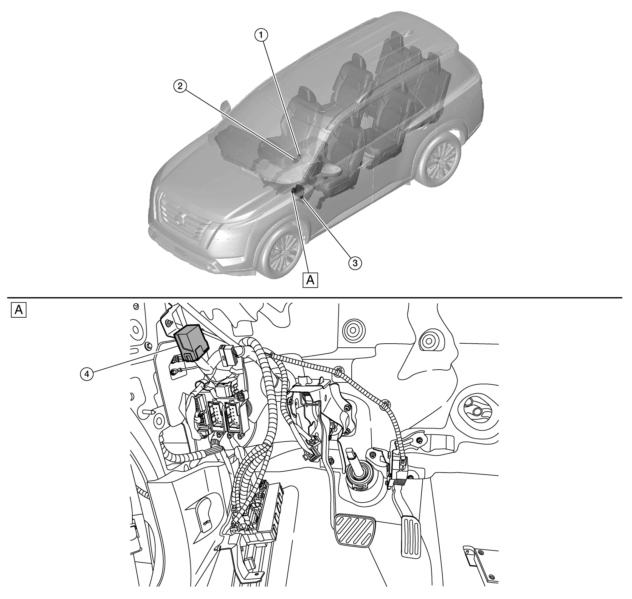
| A. | View with instrument panel assembly removed |
| No. | Component | Function |
|---|---|---|
| 1. | Drive mode select switch (with 2WD system) | Transmits the drive mode select switch status signal to BCM. BCM transmits the signal to ADAS control unit 2 via CAN communication. Refer to Component Parts Location for detailed component location. |
| Drive mode select switch (with 4WD system) | ||
| 2. | Parking brake switch | Transmits parking brake switch operation signal to chassis control module. Refer to Component Parts Location for detailed component location. |
| 3. | BCM (Body Control Module) | Transmits the drive mode select switch signal to chassis control module via CAN communication. Refer to Component Parts Location for detailed component location. |
| 4. | Chassis control module | Refer to Chassis Control Module. |
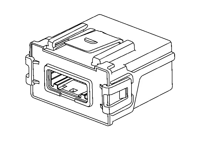
Chassis Control Module
FUNCTIONS WITHIN THE SYSTEM
Chassis control module controls the following systems based on the signals from each sensor, each switch, and each control unit.
Intelligent trace control function
Active ride control function (if equipped)
Automatic brake hold function
Drive mode selector function
INDIVIDUAL FUNCTIONS WITHIN THE SYSTEM
Receives the signals from each control unit via CAN communication.
Transmits the signals to each control unit via CAN communication.
INDIVIDUAL OPERATION
Intelligent trace control function: Refer to System Description.
Active ride control function (if equipped): Refer to System Description.
Automatic brake hold function: Refer to System Description.
Drive mode selector function
2WD models: Refer to System Description (2WD Models).
4WD models: Refer to System Description (4WD Models).
PARTS LOCATION
Refer to Component Parts Location.
System ➤ Nissan Pathfinder R53
Diagnosis System (chassis Control Module) Nissan Pathfinder 2022
CONSULT Function
APPLICATION ITEMS
CONSULT can display each diagnostic item using the diagnostic test modes as follows.
| Diagnosis mode | CGW Status | Description | ||
|---|---|---|---|---|
| Restricted Mode | Diag Test Mode | Open Mode | ||
| Self Diagnostic Result | Display | Display | Display | Display non-network DTC which chassis control module memorizes |
| CGW Information*1 | Display*1 | Display*1 | Display*1 |
|
| Data Monitor | Display | Display | Display | Displays chassis control module input/output data in real time |
| Active Test*1 | Nondisplay*1 | Display*1 | Display*1 | Enables an operational check of a load by transmitting a driving signal from the chassis control module to the load |
| ECU Identification | Display | Display | Display | Displays chassis control module part number |
| Re/programming, Configuration*2 | Display | Display | Display |
|
| Network-DTC*2 | Display | Display | Display | Display network DTC which chassis control module memorizes when performing "Diagnosis (All System)". |
| CAN Diag Support Monitor*2 | Display | Display | Display | |
| MAC Diagnosis*2 | Display | Display | Display | Display MAC diagnosis result divided into the following two inspection priorities.
|
*1: In some vehicles, it is not malfunctioning in case of no display of "CGW Information". In this case, it is not necessary to switch the CGW status.
In vehicles where "CGW information" is not displayed, "Work Support" and "Active Test" are always displayed.
*2: Displays when performing "Diagnosis (All System)".
SELF DIAGNOSTIC RESULT
Refer to DTC Index.
When “CRNT” is displayed on self-diagnosis result
The system is presently malfunctioning.
When “PAST” is displayed on self-diagnosis result
System malfunction in the past is detected, but the system is presently normal.
Freeze frame data (FFD)
When DTC is detected, a vehicle state shown below is recorded and displayed on CONSULT.
| Item | Unit | Description |
|---|---|---|
| ODO/TRIP METER | km or mile | Displays the total mileage (Odometer value) of the moment a particular. |
| DTC count | Count | Displays the number of times DTC is detected. |
| DTC LOCAL CODE | — | Displays but not used. |
| Variant code | — | Displays but not used. |
| Battery voltage | V | Displays the 12V battery power supply voltage. |
| ACC voltage | V | Displays the ACC power supply voltage. |
| Diag permission condition | Not permission / Permission / Abnormal | Displays the CAN network diagnosis status. |
| Chassis control malfunction display | On / Off | Displays the status of requesting to display the chassis control warning on the information display. |
| Nissan Pathfinder Vehicle SPEED | km/h | Displays the Nissan Pathfinder vehicle speed. |
| FR WHEEL SPEED | rpm | Displays the rotational speed of front RH tire. |
| FL WHEEL SPEED | rpm | Displays the rotational speed of front LH tire. |
| RR WHEEL SPEED | rpm | Displays the rotational speed of rear RH tire. |
| RL WHEEL SPEED | rpm | Displays the rotational speed of rear LH tire. |
| STEERING ANG SENSOR | deg | Displays the steering angle from the steering angle sensor. |
| DECEL G SENSOR | G | Displays the decel G. |
| SIDE G SENSOR | G | Displays the side G. |
| ACCELE PEDAL POSITION | % | Displays the accelerator pedal position. |
| PRESS SENSOR | bar | Displays the brake fluid pressure. |
| Throttle control | Normal / Abnormal 1 / Abnormal 2 / Abnormal 3 | Displays the electric throttle status. |
| SHIFT POSITION | Off / P / R / N / D(A) / S / L / B / 1 / 2 / 3 / 4 /5 / 6 / 7 / 8 / 9 / A1 /A2 / 10 / A3 / A4 / A5 / A6 / A7 / A8 / M1 / A9 / A10 / M2 / M3 / M4 / M5 / M6 / M7 / M8 / M9 / M10 | Displays the shift position. |
| STOP LAMP SW | Brake pedal not operation / Brake pedal operation 1 / Brake pedal operation 2 / Abnormal | Displays the stop lamp switch status. |
| Steering angle sensor | Calibration incomplete 1 / Calibration incomplete 2 / Malfunction / Calibration complete 1 / Calibration complete 2 | Displays the calibration of steering neutral position status. |
| ABS | INACT / ACTIVE | Displays the ABS function status. |
| ABS MALF | On / Off | Displays the ABS function malfunction status. |
| TCS | INACT / ACTIVE | Displays the TCS function status. |
| TCS MALF | On / Off | Displays the TCS function malfunction status. |
| VDC | INACT / ACTIVE | Displays the VDC function status. |
| VDC MALF | On / Off | Displays the VDC function malfunction status. |
| VDC OFF SWITCH | On / Off | Displays the VDC function OFF status. |
| Parking brake operation status | Release / Apply / Abnormal | Displays the electric parking brake system status. |
| Stop hold (VDC) | Release / Hold / Impossible | Displays the standstill status of VDC function. |
| FR wheel speed pulse (stop hold) | — | Displays the wheel speed pulse count on hold (front RH) |
| FL wheel speed pulse (stop hold) | — | Displays the wheel speed pulse count on hold (front LH) |
| RR wheel speed pulse (stop hold) | — | Displays the wheel speed pulse count on hold (rear RH) |
| RL wheel speed pulse (stop hold) | — | Displays the wheel speed pulse count on hold (rear LH) |
| ICC status | Off / Operation / Stop / Wait / Suspend / Brake mode / Regulation / Driver override / Malfunction | Displays the control status of ADAS system. |
| ABH warning display request | No request / Request | Displays the status of requesting to display the automatic brake hold warning on the information display. |
| ABH select status | OFF mode / STEP mode / AUTO mode | Displays the select status of automatic brake hold function. |
| ABH status 1 | Inactive / Active | Displays the automatic brake hold function status. |
| ABH status 2 | Inactive / Active | Displays the automatic brake hold function status. |
| EPB active request (ABH) | No request / Request | Displays the electric parking brake active request status from automatic brake hold function. |
| ABH stop hold request 2 | NO REQ / REQ | Displays the standstill request of automatic brake hold function. |
| ABH status 3 | —*1 No request / Request*2 |
Displays but not used.*1 Displays the automatic brake hold function status.*2 |
| ProPILOT stop hold status | —*1 No request / Request*2 |
Displays but not used.*1 Displays the standstill request status of ProPILOT (current)*2 |
| EPB active request (ProPILOT) | —1 Inactive / Request*2 |
Displays but not used.*1 Displays the chang request status ProPILOT to electric parking brake system.*2 |
| ABH active request (ProPILOT) | —*1 No request / Request*2 |
Displays but not used.*1 Displays the standstill request status of ProPILOT.*2 |
| DRIVE MODE SELECTOR | Mode 0 - 30 | Displays the select status of drive mode selector function. |
| User | — | Displays but not used. |
| Drive Mode Selector | —*3 Position 0 - 255*4 |
Displays but not used.*3 Displays the selected mode of drive mode select switch.*4 |
| Engine/TM setting | — | Displays but not used. |
| STRG SETTING | — | Displays but not used. |
| 4WD setting | — | Displays but not used. |
| ATC SETTING | — | Displays but not used. |
| ICC setting | — | Displays but not used. |
| I-KEY LINK | — | Displays but not used. |
| LOG-IN PERMIS | — | Displays but not used. |
| Drive mode select switch (UP) | Not operation / Operation*3 —*4 |
Displays the "Up" operation status of drive mode select switch.*3 Displays but not used.*4 |
| Drive mode select switch (DOWN) | Not operation / Operation*3 —*4 |
Displays the "Down" operation status of drive mode select switch.*3 Displays but not used.*4 |
*1: Without ProPILOT models
*2: With ProPILOT models
*3: 2WD models
*4: 4WD models
CGW INFORMATION
Display the diagnosis mode which a user can perform in Diag Test mode/Open Mode by switching the CGW status form Restricted mode to Diag Test Mode/Open Mode.
For the method of switching CAN Gateway status, refer to CONSULT Function.
DATA MONITOR
| Item | Unit | Description |
|---|---|---|
| Battery voltage | V | Displays the 12V battery power supply voltage. |
| ACC voltage | V | Displays the ACC power supply voltage. |
| CONTROL MODULE MALF | On / Off | Displays the chassis control module malfunction. |
| Diag permission condition | Not permission / Permission / Abnormal | Displays the CAN network diagnosis status. |
| Chassis control malfunction display | On / Off | Displays the status of requesting to display the chassis control warning on the information display. |
| Nissan Pathfinder Vehicle SPEED | km/h | Displays the vehicle speed. |
| Nissan Pathfinder Vehicle speed | km/h | Displays the wheel speed. |
| FR WHEEL SPEED | rpm | Displays the rotational speed of front RH tire. |
| FL WHEEL SPEED | rpm | Displays the rotational speed of front LH tire. |
| RR WHEEL SPEED | rpm | Displays the rotational speed of rear RH tire. |
| RL WHEEL SPEED | rpm | Displays the rotational speed of rear LH tire. |
| STEERING ANG SENSOR | deg | Displays the steering angle from the steering angle sensor. |
| DECEL G SENSOR | G | Displays the decel G. |
| Decel G | G | Displays the decel G (after correction). |
| SIDE G SENSOR | G | Displays the side G. |
| YAW RATE SENSOR | deg/s | Displays the yaw rate. |
| ACCELE PEDAL POSITION | % | Displays the accelerator pedal position. |
| PRESS SENSOR | bar | Displays the brake fluid pressure. |
| Throttle control | Normal / Abnormal 1 / Abnormal 2 / Abnormal 3 | Displays the electric throttle status. |
| SHIFT POSITION | Off / P / R / N / D(A) / S / L / B / 1 / 2 / 3 / 4 /5 / 6 / 7 / 8 / 9 / A1 /A2 / 10 / A3 / A4 / A5 / A6 / A7 / A8 / M1 / A9 / A10 / M2 / M3 / M4 / M5 / M6 / M7 / M8 / M9 / M10 | Displays the shift position. |
| STOP LAMP SW | Brake pedal not operation / Brake pedal operation 1 / Brake pedal operation 2 / Abnormal | Displays the stop lamp switch status. |
| ABS | INACT / ACTIVE | Displays the ABS function status. |
| ABS MALF | On / Off | Displays the ABS function malfunction status. |
| EBD | INACT / ACTIVE | Displays the EBD function status. |
| TCS | INACT / ACTIVE | Displays the TCS function status. |
| TCS MALF | On / Off | Displays the TCS function malfunction status. |
| VDC | INACT / ACTIVE | Displays the VDC function status. |
| VDC MALF | On / Off | Displays the VDC function malfunction status. |
| VDC OFF SWITCH | On / Off | Displays the VDC function OFF status. |
| ICC brake active status | Abnormal / NO PER / PERMIT | Displays the execution status for braking function of ADAS system. |
| Yaw rate (ADAS) | Braking / No braking / Abnormal | Displays the execution status for yaw function of ADAS system. |
| ProPILOT park | — | Displays but not used. |
| Brake torque request | Nm | Displays the brake torque value of active ride control. |
| Command BR torque (CCS) | — | Displays but not used. |
| Command BR torque (HPCM) | — | Displays but not used. |
| Command BR torque (ADAS) 1 | Nm | Displays the control command brake torque from ADAS control unit 2 (Longitudinal direction). |
| Command BR torque (ADAS) 2 | Nm | Displays the control command brake torque from ADAS control unit 2 (Turn direction). |
| Reg brake request (HPCM) | — | Displays but not used. |
| Driver brake torque request | — | Displays but not used. |
| CC/SL active status 1 | — | Displays but not used. |
| Yaw control status | — | Displays but not used. |
| Control status (VDC) 1 | Impossi / Possible | Displays the control command accept status of VDC function (Longitudinal direction). |
| Control status (VDC) 2 | Impossi / Possible | Displays the control command accept status of VDC function (Lateral direction). |
| Maintenance mode status | NOT / No req / request / Unavail | Displays the maintenance mode status. |
| Reg brake status (VDC) | — | Displays but not used. |
| Engine control status 1 | — | Displays but not used. |
| Engine control status 2 | — | Displays but not used. |
| CC/SL active status 2 | — | Displays but not used. |
| Brake active request (ADAS) 1 | Impossi / Possible | Displays the brake request accept status from VDC function. |
| Brake active request (ADAS) 2 | Inactive / 1 / 2 | Displays the brake request status from ADAS control unit 2 (longitudinal direction). |
| Brake active request (ADAS) 3 | NO REQ / REQ | Displays the brake request status from ADAS control unit 2 (Lateral direction). |
| Rear wheel steering status 1 | — | Displays but not used. |
| Rear wheel steering status 2 | — | Displays but not used. |
| ATC/ITC status 2 | Normal / Malf | Displays the intelligent trace control function status. |
| ATC/ITC status 3 | Normal / Malf | Displays the intelligent trace control function status. |
| ATC/ITC status 4 | Normal / Malf | Displays the intelligent trace control function status. |
| ATC/ITC status 5 | Normal / Malf | Displays the intelligent trace control function status. |
| ITC/ATC status (ENG control) 1 | — | Displays but not used. |
| ITC/ATC status (ENG control) 2 | — | Displays but not used. |
| ITC/ATC status (BR control) 1 | — | Displays but not used. |
| ITC/ATC status (BR control) 2 | — | Displays but not used. |
| IEB/AEB status 1 | — | Displays but not used. |
| IEB/AEB status 2 | — | Displays but not used. |
| ARC/IRC status 1 | Normal / Malf | Displays the active ride control function status. |
| ARC/IRC status 2 | Normal / Malf | Displays the active ride control function status. |
| Chassis control (ADAS) 1 | Normal / Malf | Display the status of ADAS control unit 2 (longitudinal direction). |
| Chassis control (ADAS) 2 | Normal / Malf | Display the status of ADAS control unit 2 (Lateral direction). |
| ARC/IRC status 3 | Normal / Malf | Displays the active ride control function status. |
| ARC/IRC status 4 | Normal / Malf | Displays the active ride control function status. |
| Parking brake operation status | Release / Apply / Abnormal | Displays the electric parking brake system status. |
| Stop hold (VDC) | Release / Hold / Impossible | Displays the standstill status of VDC function. |
| FR wheel speed pulse (stop hold) | — | Displays the wheel speed pulse count on hold (front RH). |
| FL wheel speed pulse (stop hold) | — | Displays the wheel speed pulse count on hold (front LH). |
| RR wheel speed pulse (stop hold) | — | Displays the wheel speed pulse count on hold (rear RH). |
| RL wheel speed pulse (stop hold) | — | Displays the wheel speed pulse count on hold (rear LH). |
| ICC status | Off / Operation / Stop / Wait / Suspend / Brake mode / Regulation / Driver override / Malfunction | Displays the control status of ADAS system. |
| ABH warning display request | No request / Request | Displays the status of requesting to display the automatic brake hold warning on the information display. |
| ABH select status | OFF mode / STEP mode / AUTO mode | Displays the select status of automatic brake hold function. |
| ABH status 1 | Inactive / Active | Displays the automatic brake hold function status. |
| ABH status 2 | Inactive / Active | Displays the automatic brake hold function status. |
| EPB active request (ABH) | No request / Request | Displays the electric parking brake active request status from automatic brake hold function. |
| ABH stop hold request 2 | NO REQ / REQ | Displays the standstill request of automatic brake hold function. |
| ABH status 3 | —*1 No request / Request*2 |
Displays but not used.*1 Displays the automatic brake hold function status.*2 |
| ProPILOT stop hold status | —*1 No request / Active*2 |
Displays but not used.*1 Displays the standstill request status of ProPILOT (current).*2 |
| EPB active request (ProPILOT) | —*1 Inactive / Request*2 |
Displays but not used.*1 Displays the electric parking brake active request of ProPILOT.*2 |
| ABH active request (ProPILOT) | —*1 No request / Request*2 |
Displays but not used.*1 Displays the automatic brake hold active request of ProPILOT.*2 |
| ABH SW 2 | No push / Push | Displays the automatic brake hold switch status. |
| ABH SW indicator lamp 3 | On / Off | Display the lighting request of automatic brake hold switch indicator. |
| DRIVE MODE SELECTOR | Mode 0 - 30 | Displays the select status of drive mode selector function. |
| User | — | Displays but not used. |
| Drive Mode Selector | —*3 Position 0 - 255*4 |
Displays but not used.*3 Displays the selected mode of drive mode select switch.*4 |
| Engine/TM setting | — | Displays but not used. |
| STRG SETTING | — | Displays but not used. |
| 4WD setting | — | Displays but not used. |
| ATC SETTING | — | Displays but not used. |
| ICC setting | — | Displays but not used. |
| I-KEY LINK | — | Displays but not used. |
| LOG-IN PERMIS | — | Displays but not used. |
| Drive mode select switch (UP) | Not operation / Operation*3 —*4 |
Displays the "Up" operation status of drive mode select switch.*3 Displays but not used.*4 |
| Drive mode select switch (DOWN) | Not operation / Operation*3 —*4 |
Displays the "Down" operation status of drive mode select switch.*3 Displays but not used.*4 |
*1: Without ProPILOT models
*2: With ProPILOT models
*3: 2WD models
*4: 4WD models
ACTIVE TEST
The "Active Test" is used to determine and identify details of a malfunction, based on self-diagnosis test results and data obtained in the "Data Monitor". In response to instructions from CONSULT, instead of those from chassis control module on the Nissan Pathfinder vehicle, a drive signal is sent to the actuator to check its operation.
| Test item | Operation | Description |
|---|---|---|
| BRAKE ACTUATOR 1 MODE 1 | — | Displays but not used. |
| BRAKE ACTUATOR 1 MODE 2 | — | Displays but not used. |
| BRAKE ACTUATOR 1 MODE 3 | — | Displays but not used. |
| MASTER WARNING ACTIVE | On | Turn ON the master warning lamp in combination meter. |
| Off | Turn OFF the master warning lamp in combination meter. | |
| Automatic brake hold lamp active | Standby (white) lamp lighting | Turn ON the automatic brake hold indicator lamp (white) in combination meter. |
| Operation (green) lamp lighting | Turn ON the automatic brake hold indicator lamp (green) in combination meter. | |
| Off | Turn OFF the automatic brake hold indicator lamp in combination meter. | |
| Automatic brake hold SW lamp active | LED lighting | Turn ON the automatic brake hold switch indicator. |
| LED blinking (1Hz) | Blink the automatic brake hold switch indicator. | |
| Off | Turn OFF the automatic brake hold switch indicator. |
WORK SUPPORT
| Item | Description |
| MAC KEY writing | Write MAC key to chassis control module. |
ECU IDENTIFICATION
Chassis control module part number and hardware part number can be read.
RE/PROGRAMMING, CONFIGURATION
Programing includes the following functions.
| Function | Description | |
|---|---|---|
| Read Write Configuration | Before replacing ECU |
|
| After replacing ECU | Allows the writing of Nissan Pathfinder vehicle information (parts number) stored in CONSULT into the chassis control module. | |
NETWORK-DTC
Refer to DTC Index.
When “CRNT” is displayed on self-diagnosis result
The system is presently malfunctioning.
When “PAST” is displayed on self-diagnosis result
System malfunction in the past is detected, but the system is presently normal.
Freeze frame data (FFD)
When DTC is detected, a vehicle state shown below is recorded and displayed on CONSULT.
| Item | Unit | Description |
|---|---|---|
| ODO/TRIP METER | km or mile | Displays the total mileage (Odometer value) of the moment a particular. |
| DTC count | Count | Displays the number of times DTC is detected. |
| DTC LOCAL CODE | — | Displays but not used. |
| Variant code | — | Displays but not used. |
| Battery voltage | V | Displays the 12V battery power supply voltage. |
| ACC voltage | V | Displays the ACC power supply voltage. |
| Diag permission condition | Not permission / Permission / Abnormal | Displays the CAN network diagnosis status. |
| Chassis control malfunction display | On / Off | Displays the status of requesting to display the chassis control warning on the information display. |
| Nissan Pathfinder Vehicle SPEED | km/h | Displays the Nissan Pathfinder vehicle speed. |
| FR WHEEL SPEED | rpm | Displays the rotational speed of front RH tire. |
| FL WHEEL SPEED | rpm | Displays the rotational speed of front LH tire. |
| RR WHEEL SPEED | rpm | Displays the rotational speed of rear RH tire. |
| RL WHEEL SPEED | rpm | Displays the rotational speed of rear LH tire. |
| STEERING ANG SENSOR | deg | Displays the steering angle from the steering angle sensor. |
| DECEL G SENSOR | G | Displays the decel G. |
| SIDE G SENSOR | G | Displays the side G. |
| ACCELE PEDAL POSITION | % | Displays the accelerator pedal position. |
| PRESS SENSOR | bar | Displays the brake fluid pressure. |
| Throttle control | Normal / Abnormal 1 / Abnormal 2 / Abnormal 3 | Displays the electric throttle status. |
| SHIFT POSITION | Off / P / R / N / D(A) / S / L / B / 1 / 2 / 3 / 4 /5 / 6 / 7 / 8 / 9 / A1 /A2 / 10 / A3 / A4 / A5 / A6 / A7 / A8 / M1 / A9 / A10 / M2 / M3 / M4 / M5 / M6 / M7 / M8 / M9 / M10 | Displays the shift position. |
| STOP LAMP SW | Brake pedal not operation / Brake pedal operation 1 / Brake pedal operation 2 / Abnormal | Displays the stop lamp switch status. |
| Steering angle sensor | Calibration incomplete 1 / Calibration incomplete 2 / Malfunction / Calibration complete 1 / Calibration complete 2 | Displays the calibration of steering neutral position status. |
| ABS | INACT / ACTIVE | Displays the ABS function status. |
| ABS MALF | On / Off | Displays the ABS function malfunction status. |
| TCS | INACT / ACTIVE | Displays the TCS function status. |
| TCS MALF | On / Off | Displays the TCS function malfunction status. |
| VDC | INACT / ACTIVE | Displays the VDC function status. |
| VDC MALF | On / Off | Displays the VDC function malfunction status. |
| VDC OFF SWITCH | On / Off | Displays the VDC function OFF status. |
| Parking brake operation status | Release / Apply / Abnormal | Displays the electric parking brake system status. |
| Stop hold (VDC) | Release / Hold / Impossible | Displays the standstill status of VDC function. |
| FR wheel speed pulse (stop hold) | — | Displays the wheel speed pulse count on hold (front RH) |
| FL wheel speed pulse (stop hold) | — | Displays the wheel speed pulse count on hold (front LH) |
| RR wheel speed pulse (stop hold) | — | Displays the wheel speed pulse count on hold (rear RH) |
| RL wheel speed pulse (stop hold) | — | Displays the wheel speed pulse count on hold (rear LH) |
| ICC status | Off / Operation / Stop / Wait / Suspend / Brake mode / Regulation / Driver override / Malfunction | Displays the control status of ADAS system. |
| ABH warning display request | No request / Request | Displays the status of requesting to display the automatic brake hold warning on the information display. |
| ABH select status | OFF mode / STEP mode / AUTO mode | Displays the select status of automatic brake hold function. |
| ABH status 1 | Inactive / Active | Displays the automatic brake hold function status. |
| ABH status 2 | Inactive / Active | Displays the automatic brake hold function status. |
| EPB active request (ABH) | No request / Request | Displays the electric parking brake active request status from automatic brake hold function. |
| ABH stop hold request 2 | NO REQ / REQ | Displays the standstill request of automatic brake hold function. |
| ABH status 3 | —*1 No request / Request*2 |
Displays but not used.*1 Displays the automatic brake hold function status.*2 |
| ProPILOT stop hold status | —*1 No request / Request*2 |
Displays but not used.*1 Displays the standstill request status of ProPILOT (current)*2 |
| EPB active request (ProPILOT) | —1 Inactive / Request*2 |
Displays but not used.*1 Displays the chang request status ProPILOT to electric parking brake system.*2 |
| ABH active request (ProPILOT) | —*1 No request / Request*2 |
Displays but not used.*1 Displays the standstill request status of ProPILOT.*2 |
| DRIVE MODE SELECTOR | Mode 0 - 30 | Displays the select status of drive mode selector function. |
| User | — | Displays but not used. |
| Drive Mode Selector | —*3 Position 0 - 255*4 |
Displays but not used.*3 Displays the selected mode of drive mode select switch.*4 |
| Engine/TM setting | — | Displays but not used. |
| STRG SETTING | — | Displays but not used. |
| 4WD setting | — | Displays but not used. |
| ATC SETTING | — | Displays but not used. |
| ICC setting | — | Displays but not used. |
| I-KEY LINK | — | Displays but not used. |
| LOG-IN PERMIS | — | Displays but not used. |
| Drive mode select switch (UP) | Not operation / Operation*3 —*4 |
Displays the "Up" operation status of drive mode select switch.*3 Displays but not used.*4 |
| Drive mode select switch (DOWN) | Not operation / Operation*3 —*4 |
Displays the "Down" operation status of drive mode select switch.*3 Displays but not used.*4 |
*1: Without ProPILOT models
*2: With ProPILOT models
*3: 2WD models
*4: 4WD models
MAC DIAGNOSIS
Refer to DTC Index.
When “CRNT” is displayed on self-diagnosis result
The system is presently malfunctioning.
When “PAST” is displayed on self-diagnosis result
System malfunction in the past is detected, but the system is presently normal.
Freeze frame data (FFD)
When DTC is detected, a vehicle state shown below is recorded and displayed on CONSULT.
| Item | Unit | Description |
|---|---|---|
| ODO/TRIP METER | km or mile | Displays the total mileage (Odometer value) of the moment a particular. |
| DTC count | Count | Displays the number of times DTC is detected. |
| DTC LOCAL CODE | — | Displays but not used. |
| Variant code | — | Displays but not used. |
| Battery voltage | V | Displays the 12V battery power supply voltage. |
| ACC voltage | V | Displays the ACC power supply voltage. |
| Diag permission condition | Not permission / Permission / Abnormal | Displays the CAN network diagnosis status. |
| Chassis control malfunction display | On / Off | Displays the status of requesting to display the chassis control warning on the information display. |
| Nissan Pathfinder Vehicle SPEED | km/h | Displays the Nissan Pathfinder vehicle speed. |
| FR WHEEL SPEED | rpm | Displays the rotational speed of front RH tire. |
| FL WHEEL SPEED | rpm | Displays the rotational speed of front LH tire. |
| RR WHEEL SPEED | rpm | Displays the rotational speed of rear RH tire. |
| RL WHEEL SPEED | rpm | Displays the rotational speed of rear LH tire. |
| STEERING ANG SENSOR | deg | Displays the steering angle from the steering angle sensor. |
| DECEL G SENSOR | G | Displays the decel G. |
| SIDE G SENSOR | G | Displays the side G. |
| ACCELE PEDAL POSITION | % | Displays the accelerator pedal position. |
| PRESS SENSOR | bar | Displays the brake fluid pressure. |
| Throttle control | Normal / Abnormal 1 / Abnormal 2 / Abnormal 3 | Displays the electric throttle status. |
| SHIFT POSITION | Off / P / R / N / D(A) / S / L / B / 1 / 2 / 3 / 4 /5 / 6 / 7 / 8 / 9 / A1 /A2 / 10 / A3 / A4 / A5 / A6 / A7 / A8 / M1 / A9 / A10 / M2 / M3 / M4 / M5 / M6 / M7 / M8 / M9 / M10 | Displays the shift position. |
| STOP LAMP SW | Brake pedal not operation / Brake pedal operation 1 / Brake pedal operation 2 / Abnormal | Displays the stop lamp switch status. |
| Steering angle sensor | Calibration incomplete 1 / Calibration incomplete 2 / Malfunction / Calibration complete 1 / Calibration complete 2 | Displays the calibration of steering neutral position status. |
| ABS | INACT / ACTIVE | Displays the ABS function status. |
| ABS MALF | On / Off | Displays the ABS function malfunction status. |
| TCS | INACT / ACTIVE | Displays the TCS function status. |
| TCS MALF | On / Off | Displays the TCS function malfunction status. |
| VDC | INACT / ACTIVE | Displays the VDC function status. |
| VDC MALF | On / Off | Displays the VDC function malfunction status. |
| VDC OFF SWITCH | On / Off | Displays the VDC function OFF status. |
| Parking brake operation status | Release / Apply / Abnormal | Displays the electric parking brake system status. |
| Stop hold (VDC) | Release / Hold / Impossible | Displays the standstill status of VDC function. |
| FR wheel speed pulse (stop hold) | — | Displays the wheel speed pulse count on hold (front RH) |
| FL wheel speed pulse (stop hold) | — | Displays the wheel speed pulse count on hold (front LH) |
| RR wheel speed pulse (stop hold) | — | Displays the wheel speed pulse count on hold (rear RH) |
| RL wheel speed pulse (stop hold) | — | Displays the wheel speed pulse count on hold (rear LH) |
| ICC status | Off / Operation / Stop / Wait / Suspend / Brake mode / Regulation / Driver override / Malfunction | Displays the control status of ADAS system. |
| ABH warning display request | No request / Request | Displays the status of requesting to display the automatic brake hold warning on the information display. |
| ABH select status | OFF mode / STEP mode / AUTO mode | Displays the select status of automatic brake hold function. |
| ABH status 1 | Inactive / Active | Displays the automatic brake hold function status. |
| ABH status 2 | Inactive / Active | Displays the automatic brake hold function status. |
| EPB active request (ABH) | No request / Request | Displays the electric parking brake active request status from automatic brake hold function. |
| ABH stop hold request 2 | NO REQ / REQ | Displays the standstill request of automatic brake hold function. |
| ABH status 3 | —*1 No request / Request*2 |
Displays but not used.*1 Displays the automatic brake hold function status.*2 |
| ProPILOT stop hold status | —*1 No request / Request*2 |
Displays but not used.*1 Displays the standstill request status of ProPILOT (current)*2 |
| EPB active request (ProPILOT) | —1 Inactive / Request*2 |
Displays but not used.*1 Displays the chang request status ProPILOT to electric parking brake system.*2 |
| ABH active request (ProPILOT) | —*1 No request / Request*2 |
Displays but not used.*1 Displays the standstill request status of ProPILOT.*2 |
| DRIVE MODE SELECTOR | Mode 0 - 30 | Displays the select status of drive mode selector function. |
| User | — | Displays but not used. |
| Drive Mode Selector | —*3 Position 0 - 255*4 |
Displays but not used.*3 Displays the selected mode of drive mode select switch.*4 |
| Engine/TM setting | — | Displays but not used. |
| STRG SETTING | — | Displays but not used. |
| 4WD setting | — | Displays but not used. |
| ATC SETTING | — | Displays but not used. |
| ICC setting | — | Displays but not used. |
| I-KEY LINK | — | Displays but not used. |
| LOG-IN PERMIS | — | Displays but not used. |
| Drive mode select switch (UP) | Not operation / Operation*3 —*4 |
Displays the "Up" operation status of drive mode select switch.*3 Displays but not used.*4 |
| Drive mode select switch (DOWN) | Not operation / Operation*3 —*4 |
Displays the "Down" operation status of drive mode select switch.*3 Displays but not used.*4 |
*1: Without ProPILOT models
*2: With ProPILOT models
*3: 2WD models
*4: 4WD models