Srs Air Bag Control System - System Description

In this manual: Srs Air Bag Control System - System Description
General Information — 8Engine :: Engine Mechanical — 19Engine Lubrication System - Precautions. Preparation — 1Engine Lubrication System - Lubrication System (System Description). Engine Oil Pressure (Basic Inspection). Service Data and Specifications (SDS) — 1Engine Cooling System - Precautions. Preparation. Service Data and Specifications (SDS) — 1Engine Cooling System - Engine Coolant — 1Engine Control System - System Description — 1System Description - Component Parts ++ — 1System Description - System ++ — 1Engine Control System - Ecu Diagnosis Information — 1Ecu Diagnosis Information - Ecm ++ — 1Engine Control System - Basic Inspection — 1Basic Inspection - Diagnosis and Repair Workflow ++ — 1Basic Inspection - Basic Inspection ++ — 1Basic Inspection - Additional Service When Replacing Ecm ++ — 1Basic Inspection - Fuel Pressure Check ++ — 1Basic Inspection - How to Set Srt Code ++ — 1Basic Inspection - How to Erase Permanent Dtc ++ — 1Engine Control System - Dtc/circuit Diagnosis — 1Engine Control System - Symptom Diagnosis — 1Engine Control System - Periodic Maintenance — 1Engine Control System - Removal and Installation — 1Fuel System - Precautions. Preparation. Service Data and Specifications (SDS) — 1Fuel System - Fuel System (Periodic Maintenance). Fuel Level Sensor Unit (Disassembly and Assembly) — 1Exhaust System - Precautions. Preparation — 1Exhaust System - Exhaust System (Periodic Maintenance). Exhaust System (Removal and Installation) — 1Starting System - Precautions. Preparation. Starter Motor (Service Data and Specifications (sds)) — 1Starting System - Diagnosis and Repair Work Flow — 1Starting System - Starting System (Symptom Diagnosis). Starter Motor (Removal and Installation) — 1Accelerator Control System - Precautions. Service Data and Specifications (SDS) — 1Accelerator Control System - Accelerator Pedal Assembly — 1Transmission & Driveline :: Transaxle & Transmission — 21Driveline - System Description — 1Transfer: Ty92b - Ecu Diagnosis Information. Awd Control Unit ++ — 1Driveline - Basic Inspection — 1Driveline - Dtc/circuit Diagnosis — 1Driveline - Symptom Diagnosis — 1Driveline - Removal and Installation — 1Transfer: Ty92b - Unit Removal and Installation. Transfer Assembly ++ — 1Driveline - Unit Disassembly and Assembly — 1Driveline - Basic Inspection — 1Driveline - Removal and Installation — 1Driveline - Unit Disassembly and Assembly — 1Front Axle - Precautions. Preparation — 1Front Axle - Noise, Vibration and Harshness (nvh) Troubleshooting (Symptom Diagnosis). Service Data and Specifications (SDS) — 1Front Axle - Front Drive Shaft Boot — 1Front Axle - Front Drive Shaft — 1Rear Axle - Precautions. Preparation. Service Data and Specifications (SDS) — 1Rear Axle - Noise, Vibration and Harshness (nvh) Troubleshooting — 1Rear Axle - Rear Drive Shaft — 1Suspension :: Front Suspension — 7Rear Suspension - Precautions. Preparation — 1Rear Suspension - Noise, Vibration and Harshness (nvh) Troubleshooting (Symptom Diagnosis). Service Data and Specifications (SDS) — 1Rear Suspension - Rear Suspension Assembly — 1Road Wheels & Tires - Precautions — 1Road Wheels & Tires - Preparation. Bcm (Ecu Diagnosis Information). Service Data and Specifications (SDS) — 1Road Wheels & Tires - System — 1Brakes :: Brake System — 9Parking Brake System - Precautions. Preparation — 1Parking Brake System - System — 1Vdc/tcs/abs - Precautions ++ — 1Brake Control System - System Description — 1System Description - Component Parts ++ — 1System Description - System ++ — 1Brake Control System - Basic Inspection — 1Brake Control System - Symptom Diagnosis — 1Brake Control System - Removal and Installation — 1Brake Control System - System Description — 1Brake Control System - Dtc/circuit Diagnosis — 1Brake Control System - Removal and Installation — 1Brake Control System - System Description — 1Brake Control System - Basic Inspection — 1Brake Control System - Symptom Diagnosis — 1Brake Control System - System Description — 1Brake Control System - Basic Inspection — 1Brake Control System - Symptom Diagnosis — 1Steering :: Steering System — 9Steering Control System - Precautions — 1Steering Control System - System — 1Steering Control System - Eps Control Unit (Ecu Diagnosis Information. Removal and Installation) — 1Restraints :: Seat Belt — 7Srs Air Bag - Precautions. Preparation — 1Srs Air Bag - Collision Diagnosis — 1Srs Air Bag - Occupant Classification System — 1Srs Air Bag Control System - Precautions — 1Srs Air Bag Control System - System — 1Srs Air Bag Control System - Diagnosis Sensor Unit — 1Srs Air Bag Control System - Inspection and Adjustment — 1Ventilation, Heater & Air Conditioner :: Ventilation System — 6Heater & Air Conditioning System - Precautions — 1Heater & Air Conditioning System - Preparation — 1Heater & Air Conditioning System - Component Parts — 1Heater & Air Conditioning System - Diagnosis and Repair Work Flow — 1Heater & Air Conditioning System - Compressor — 1Heater & Air Conditioning System - Cooler Pipe and Hose — 1Heater & Air Conditioning System - Condenser. Condenser — 1Heater & Air Conditioning System - Heating and Cooling Unit Assembly — 1Heater & Air Conditioning System - Service Data and Specifications (SDS) — 1Heater & Air Conditioning Control System - System Description — 1System Description - Component Parts ++ — 1System Description - System ++ — 1System Description - Operation ++ — 1Heater & Air Conditioning Control System - Ecu Diagnosis Information — 1Heater & Air Conditioning Control System - Basic Inspection — 1Heater & Air Conditioning Control System - Dtc/circuit Diagnosis — 1Heater & Air Conditioning Control System - Symptom Diagnosis — 1Heater & Air Conditioning Control System - Removal and Installation — 1Body Interior :: Interior — 8Instrument Panel - Precautions. Preparation. Clip List — 1Instrument Panel - Squeak and Rattle Trouble Diagnoses — 1Instrument Panel - Cluster Lid C — 1Seat - Precautions — 1Seat - Preparation. Clip List — 1Seat - Component Parts — 1Seat - System — 1Seat - Diagnosis and Repair Work Flow — 1Seat - Front Seat — 1Seat - Second Row Seats — 1Seat - Third Row Seats — 1Seat - Front Seat — 1Seat - Second Row Seat — 1Seat - Third Row Seat — 1Automatic Drive Positioner - Precautions. Preparation — 1Automatic Drive Positioner - System — 1Automatic Drive Positioner - Diagnosis and Repair Work Flow — 1Automatic Drive Positioner - Inspection and Adjustment — 1Body Exterior, Doors, Roof & Vehicle Security :: Door & Lock — 38Security Control System - Precautions — 1Security Control System - System — 1Security Control System - Ecm, Bcm, Intelligent Key Unit, Ipdm E/r — 1Security Control System - Vehicle Security System Cannot Be Set — 1Glass & Window System - Precautions. Preparation — 1Glass & Window System - Squeak and Rattle Trouble Diagnoses — 1Power Window Control System - Precautions. Preparation — 1Power Window Control System - Power Supply and Ground Circuit — 1Power Window Control System - Power Window Motor Circuit — 1Power Window Control System - Front Power Window Rh Alone Does Not Operate — 1Power Window Control System - Rear Lh Side Power Window Alone Does Not Operate — 1Power Window Control System - Rear Rh Side Power Window Alone Does Not Operate — 1Roof - Precautions. Preparation — 1Roof - Power Supply and Ground Circuit — 1Roof - Moonroof Switch Assembly — 1Roof - Lin Communication Circuit — 1Roof - Auto Operation Does Not Operate — 1Roof - Anti-Pinch Function Does Not Operate — 1Exterior - Precautions. Preparation. Clip List (Preparation) — 1Exterior - Squeak and Rattle Trouble Diagnoses — 1Exterior - Fender Protector — 1Exterior - Over Fender — 1Exterior - Under Cover — 1Exterior - Roof Side Rail — 1Body Repair - Service Information — 1Service Information - Sheet Metal Work ++ — 1Service Information - Body Welding and Precautions ++ — 1Service Information - Safety and Health ++ — 1Service Information - Repairing Procedures and Precautions ++ — 1Body Repair - Precaution — 1Body Repair - Preparation — 1Body Repair - Removal and Installation — 1Driver Controls :: Mirrors — 8Exterior Lighting System - System Description — 1System Description - Component Parts ++ — 1Exterior Lighting System - Basic Inspection — 1Exterior Lighting System - Dtc/circuit Diagnosis — 1Exterior Lighting System - Symptom Diagnosis — 1Exterior Lighting System - Periodic Maintenance — 1Exterior Lighting System - Removal and Installation — 1Interior Lighting System - Precautions. Preparation — 1Interior Lighting System - Component Parts. Interior Lighting System — 1Interior Lighting System - System — 1Interior Lighting System - Diagnosis and Repair Work Flow — 1Interior Lighting System - Interior Lighting System Symptoms (Symptom Diagnosis). Bcm (Ecu Diagnosis Information). Service Data and Specifications (SDS) — 1Interior Lighting System - Foot Lamp — 1Wiper & Washer - Precautions — 1Wiper & Washer - Preparation. Bcm, Ipdm E/r (Ecu Diagnosis Information). Service Data and Specifications (SDS) — 1Wiper & Washer - System — 1Wiper & Washer - Diagnosis and Repair Work Flow — 1Defogger - Precautions. Bcm, A/c Auto Amp. (Ecu Diagnosis Information) — 1Defogger - Diagnosis and Repair Work Flow — 1Horn - Precautions — 1Electrical & Power Control :: Power Outlet — 13Body Control System - Precautions. Preparation — 1Body Control System - Component Parts — 1Body Control System - System — 1Body Control System - Diagnosis System (bcm) — 1Body Control System - Bcm — 1Lan System - System Description — 1Lan System - System Description — 1Lan System - Dtc/circuit Diagnosis — 1Lan System - System Description — 1Lan System - Dtc/circuit Diagnosis — 1Power Control System - System Description — 1Power Control System - Basic Inspection — 1Power Control System - Dtc/circuit Diagnosis — 1Power Control System - System Description — 1Power Control System - Basic Inspection — 1Power Control System - Dtc/circuit Diagnosis — 1Power Control System - Removal and Installation — 1Charging System - Precautions. Preparation. Ecm, Ipdm E/r (Ecu Diagnosis Information) — 1Charging System - Diagnosis and Repair Work Flow — 1Charging System - Charging System (Symptom Diagnosis). Generator (Removal and Installation). Service Data and Specifications (SDS) — 1Power Supply, Ground & Circuit Elements - Precautions. Preparation. Service Data and Specifications (SDS) — 1Driver Information & Multimedia :: Meter, Warning Lamp & Indicator — 25Warning Chime System - Application Notice (How to Use This Manual). Precautions — 1Warning Chime System - System — 1Warning Chime System - Diagnosis System (combination Meter) — 1Warning Chime System - Bcm, Combination Meter (Ecu Diagnosis Information). Diagnosis and Repair Work Flow (Basic Inspection) — 1Sonar System - Precautions. Preparation — 1Sonar System - Sonar Control Unit — 1Dtc/circuit Diagnosis - B2720 Corner Sensor [rl] ++ — 1Audio, Visual & Navigation System - System Description — 1System Description - Component Parts ++ — 1System Description - System ++ — 1Audio, Visual & Navigation System - Ecu Diagnosis Information — 1Audio, Visual & Navigation System - Basic Inspection — 1Audio, Visual & Navigation System - Dtc/circuit Diagnosis — 1Dtc/circuit Diagnosis - Multi Av (av Control Unit) ++ — 1Audio, Visual & Navigation System - Symptom Diagnosis — 1Symptom Diagnosis - Multi Av System ++ — 1Audio, Visual & Navigation System - Removal and Installation — 1Audio, Visual & Navigation System - System Description — 1Audio, Visual & Navigation System - Ecu Diagnosis Information — 1Audio, Visual & Navigation System - Basic Inspection — 1Audio, Visual & Navigation System - Dtc/circuit Diagnosis — 1Audio, Visual & Navigation System - Symptom Diagnosis — 1Audio, Visual & Navigation System - Removal and Installation — 1Audio, Visual & Navigation System - System Description — 1Audio, Visual & Navigation System - Basic Inspection — 1Audio, Visual & Navigation System - Dtc/circuit Diagnosis — 1Audio, Visual & Navigation System - Symptom Diagnosis — 1Audio, Visual & Navigation System - Removal and Installation — 1Audio, Visual & Navigation System - System Description — 1Audio, Visual & Navigation System - Basic Inspection — 1Audio, Visual & Navigation System - Dtc/circuit Diagnosis — 1Audio, Visual & Navigation System - Symptom Diagnosis — 1Audio, Visual & Navigation System - Removal and Installation — 1Cruise Control & Driver Assistance :: Cruise Control System — 17Driver Assistance System - System Description — 1Driver Assistance System - Basic Inspection — 1Driver Assistance System - Dtc/circuit Diagnosis — 1Driver Assistance System - System Description — 1System Description - Component Parts ++ — 1System Description - System ++ — 1System Description - Operation ++ — 1System Description - Handling Precaution ++ — 1Driver Assistance System - Ecu Diagnosis Information — 1Driver Assistance System - Basic Inspection — 1Basic Inspection - Distance Sensor Alignment ++ — 1Basic Inspection - Camera Aiming Adjustment ++ — 1Basic Inspection - Action Test ++ — 1Driver Assistance System - Dtc/circuit Diagnosis — 1Dtc/circuit Diagnosis - Laser/radar (distance Sensor) ++ — 1Dtc/circuit Diagnosis - Lane Camera (front Camera Unit) ++ — 1Driver Assistance System - Symptom Diagnosis — 1Driver Assistance System - Removal and Installation — 1Driver Assistance System - System Description — 1System Description - System ++ — 1Driver Assistance System - Basic Inspection — 1Driver Assistance System - Dtc/circuit Diagnosis — 1Drive Mode System - Precautions — 1Drive Mode System - Component Parts. Drive Mode System — 1Drive Mode System - System — 1Drive Mode System - Diagnosis and Repair Work Flow — 1Drive Mode System - Drive Mode Select Switch Circuit — 1Maintenance - Precautions. Preparation — 1Maintenance - General Maintenance — 1Maintenance - Periodic Maintenance — 1Maintenance - Recommended Fluids and Lubricants — 1Maintenance - Engine Maintenance — 1Maintenance - Chassis and Body Maintenance — 1Engine Lubrication System - Periodic Maintenance — 1Engine Lubrication System - Removal and Installation — 1Engine Cooling System - System Description — 1Engine Cooling System - Removal and Installation — 1Engine Control System - Vq35dd — 1Fuel System - Removal and Installation — 1Starting System - System Description — 1Starting System - Dtc/circuit Diagnosis — 1Driveline - Transfer: Ty92b — 1Driveline - Rear Propeller Shaft: 3fcj-Cvj — 1Driveline - Rear Final Drive: R145 — 1Front Axle - Periodic Maintenance — 1Front Axle - Removal and Installation — 1Rear Axle - Periodic Maintenance — 1Rear Axle - Removal and Installation — 1Rear Suspension - Removal and Installation — 1Road Wheels & Tires - System Description — 1Road Wheels & Tires - Basic Inspection — 1Road Wheels & Tires - Dtc/circuit Diagnosis — 1Road Wheels & Tires - Symptom Diagnosis — 1Road Wheels & Tires - Periodic Maintenance — 1Road Wheels & Tires - Removal and Installation — 1Parking Brake System - System Description — 1Parking Brake System - Basic Inspection — 1Parking Brake System - Dtc/circuit Diagnosis — 1Parking Brake System - Symptom Diagnosis — 1Parking Brake System - Removal and Installation — 1Brake Control System - Vdc/tcs/abs — 1Brake Control System - Automatic Brake Hold — 1Brake Control System - Automatic Emergency Braking — 1Brake Control System - Rear Automatic Braking — 1Steering Control System - System Description — 1Steering Control System - Basic Inspection — 1Steering Control System - Dtc/circuit Diagnosis — 1Steering Control System - Symptom Diagnosis — 1Srs Air Bag - Removal and Installation — 1Srs Air Bag Control System - System Description — 1Srs Air Bag Control System - Basic Inspection — 1Srs Air Bag Control System - Symptom Diagnosis — 1Heater & Air Conditioning System - Symptom Diagnosis — 1Heater & Air Conditioning System - Periodic Maintenance — 1Heater & Air Conditioning Control System - Automatic Air Conditioning — 1Instrument Panel - Removal and Installation — 1Instrument Panel - Unit Disassembly and Assembly — 1Seat - Ecu Diagnosis Information — 1Seat - Dtc/circuit Diagnosis — 1Seat - Symptom Diagnosis — 1Automatic Drive Positioner - System Description — 1Automatic Drive Positioner - Ecu Diagnosis Information — 1Automatic Drive Positioner - Dtc/circuit Diagnosis — 1Automatic Drive Positioner - Symptom Diagnosis — 1Automatic Drive Positioner - Removal and Installation — 1Security Control System - System Description — 1Security Control System - Basic Inspection — 1Security Control System - Dtc/circuit Diagnosis — 1Security Control System - Symptom Diagnosis — 1Security Control System - Removal and Installation — 1Glass & Window System - Removal and Installation — 1Power Window Control System - System Description — 1Power Window Control System - Ecu Diagnosis Information — 1Power Window Control System - Basic Inspection — 1Power Window Control System - Dtc/circuit Diagnosis — 1Power Window Control System - Symptom Diagnosis — 1Power Window Control System - Removal and Installation — 1Roof - System Description — 1Roof - Ecu Diagnosis Information — 1Roof - Basic Inspection — 1Roof - Dtc/circuit Diagnosis — 1Roof - Symptom Diagnosis — 1Roof - Removal and Installation — 1Exterior - System Description — 1Exterior - Removal and Installation — 1Body Repair - Repair Information — 1Exterior Lighting System - Led Headlamp — 1Interior Lighting System - Dtc/circuit Diagnosis — 1Interior Lighting System - Removal and Installation — 1Wiper & Washer - System Description — 1Wiper & Washer - Dtc/circuit Diagnosis — 1Wiper & Washer - Symptom Diagnosis — 1Wiper & Washer - Removal and Installation — 1Defogger - System Description — 1Defogger - Dtc/circuit Diagnosis — 1Defogger - Symptom Diagnosis — 1Defogger - Removal and Installation — 1Horn - Removal and Installation — 1Body Control System - Basic Inspection — 1Body Control System - Dtc/circuit Diagnosis — 1Body Control System - Symptom Diagnosis — 1Body Control System - Removal and Installation — 1Lan System - Can Fundamental — 1Lan System - Can — 1Lan System - Can Gateway — 1Power Control System - Ipdm E/r — 1Power Control System - Power Distribution System — 1Charging System - System Description — 1Charging System - Dtc/circuit Diagnosis — 1Power Supply, Ground & Circuit Elements - System Description — 1Power Supply, Ground & Circuit Elements - Basic Inspection — 1Power Supply, Ground & Circuit Elements - Removal and Installation — 1Warning Chime System - System Description — 1Warning Chime System - Dtc/circuit Diagnosis — 1Warning Chime System - Symptom Diagnosis — 1Sonar System - System Description — 1Sonar System - Basic Inspection — 1Sonar System - Dtc/circuit Diagnosis — 1Sonar System - Symptom Diagnosis — 1Sonar System - Removal and Installation — 1Audio, Visual & Navigation System - Nissanconnect — 1Audio, Visual & Navigation System - Intelligent Around View Monitor System — 1Audio, Visual & Navigation System - Rear View Monitor System — 1Audio, Visual & Navigation System - Telematics System — 1Driver Assistance System - Adas Control Unit 2 — 1Driver Assistance System - Driver Assistance System — 1Driver Assistance System - Chassis Control — 1Drive Mode System - Removal and Installation — 1Dtc/circuit Diagnosis (C053c Wheel Speed Sensor ... U2141 Can Comm Circuit) — 1Dtc/circuit Diagnosis (P0011 Intake Valve Timing Control ... P0111 Iat Sensor) — 1Dtc/circuit Diagnosis (P0116 Engine Coolant Temperature Sensor ... P025b Fuel Pump Module a) — 1Dtc/circuit Diagnosis (P026b Injection Timing ... P0420 Three Way Catalyst Function) — 1Dtc/circuit Diagnosis (P0441 Evap Control System ... P0524 Engine Oil Pressure) — 1Dtc/circuit Diagnosis (P0532 A/c Refrigerant Pressure Sensor ... P064d Ecm) — 1Dtc/circuit Diagnosis (P06da Engine Oil Pressure Control Solenoid Valve ... P1217 Engine Over Temperature) — 1Dtc/circuit Diagnosis (P1220 Fuel Pump Control Module (fpcm) ... P1574 Ascd Vehicle Speed Sensor) — 1Dtc/circuit Diagnosis (P1575 Brake Switch ... P2101 Electric Throttle Control Function) — 1Dtc/circuit Diagnosis (P2118 Throttle Control Motor ... P34ac Electric Intake Valve Timing Control Actuator) — 1Dtc/circuit Diagnosis (Active Grille Shutter ... High Pressure Fuel Pump) — 1Dtc/circuit Diagnosis (Ignition Signal ... Variable Induction Air System) — 14012 C1040 Emergency Brake — 14013 C106a Wheel Sensor — 14014 C1078-55 Not Configuration — 14015 C10b4-98 Overheat — 14016 B1001 Lap Pre-Tensioner Lh — 14017 B0001 Driver Air Bag Module — 14018 B100e Knee Air Bag Module Rh — 14019 B142x Collision Detection — 1Dtc/circuit Diagnosis (B20c7-11 A/c Clutch ... B24a6-11 in-Vehicle Sensor) — 1Dtc/circuit Diagnosis (B24a6-15 in-Vehicle Sensor ... U2140-87 Can Comm Err (ecm)) — 1Dtc/circuit Diagnosis (C1f00-1c Control Unit ... C1f04-61 Brake Sw/stop Lamp Sw) — 1Dtc/circuit Diagnosis (C1f05-49 Front Camera Unit ... C1f70-87 Ethernet Circuit) — 1
20steps
~120min
5/5difficulty
Done 0 of 20
  • Component Parts. Srs Air Bag Control System
  • Diagnosis System (air Bag)

Component Parts. Srs Air Bag Control System Nissan Pathfinder

Component Parts Location
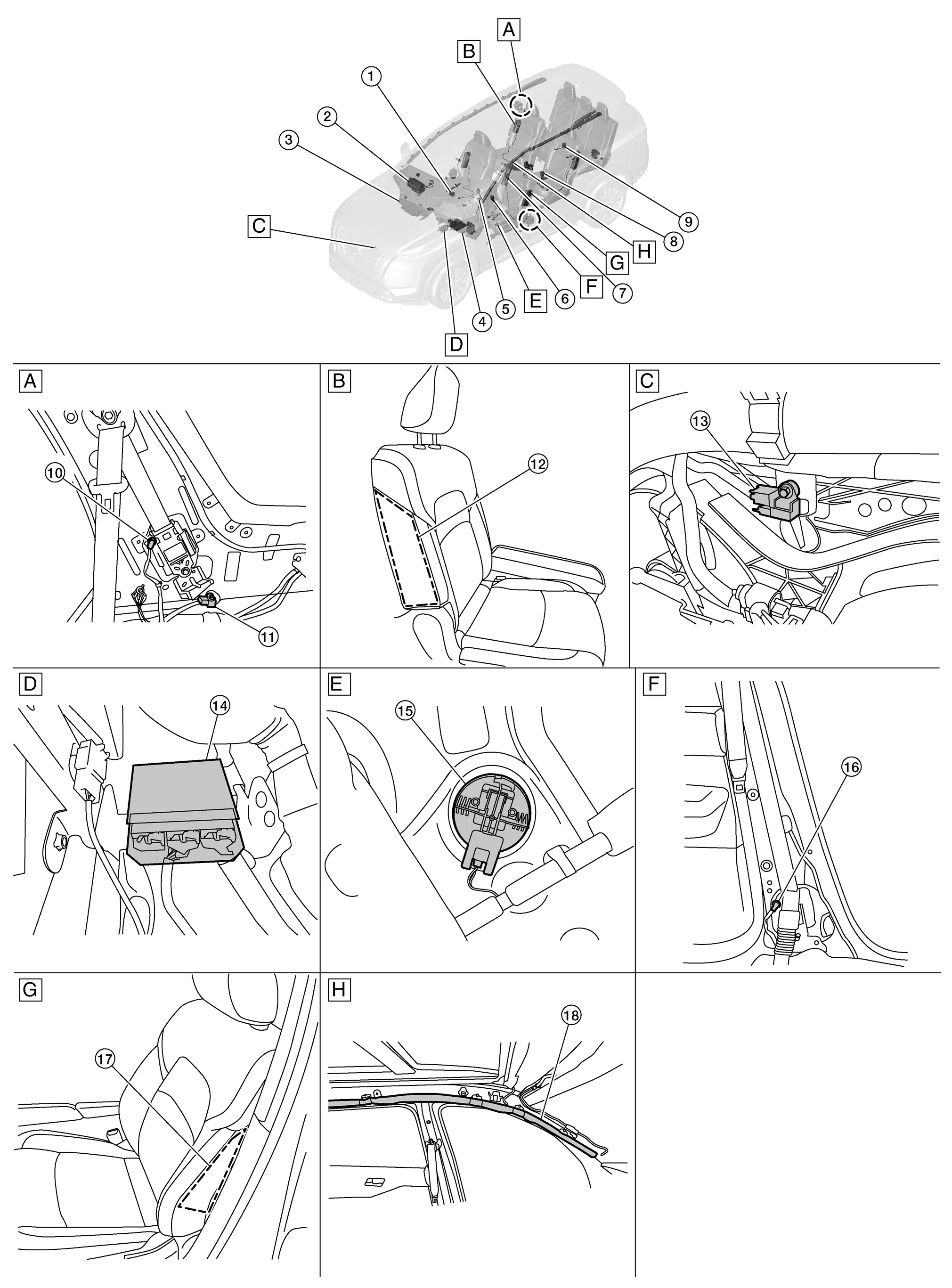
A. Right rear seat area (view with rear side finisher removed) B. Right rear seat area (view with rear side finisher removed) (view with luggage side lower finisher LH removed) C. Core support (view with air intake removed)
D. Center console area (view with center console assembly removed) E. Driver door (view with front door finisher LH removed) F. B-pillar area (view with lower center pillar cover removed)
G. Driver seat H. Roof area
No.ComponentFunction
1. Occupant classification system control unit Refer to System Description.
2. Front passenger air bag module Refer to Front Passenger Air Bag Module.
3. Knee air bag module RH (if equipped) Knee air bag module RH is built into instrument panel assembly. Knee air bag module RH mainly consists of air bag and inflator. Knee air bag RH inflates by breaking lid surface.
4. Knee air bag module LH Knee air bag module LH is built into instrument panel assembly. Knee air bag module LH mainly consists of air bag and inflator. Knee air bag LH inflates by breaking lid surface.
5. Driver air bag module Refer to Driver Air Bag Module.
6. Seat belt buckle switch LH (RH similar) The seat belt buckle switches (Front Row LH/RH, 2ND Row LH/CTR/RH, 3RD Row LH/CTR/RH ) provide the seat belt buckle signals to the air bag diagnosis sensor unit and the combination meter.
7. Front center air bag module (If equipped) Front center air bag module is built into seatback inside of driver seat. Front center air bag module mainly consists of air bag and inflator which inflates air bag. Front center air bag is installed to seatback inside stitch of driver seat indicating that front center air bag is equipped. Front center air bag inflates through seatback inside stitch of drivers seat.
8. 2nd row seat belt buckle switch LH (CTR and RH similar) The seat belt buckle switches (Front Row LH/RH, 2ND Row LH/CTR/RH, 3RD Row LH/CTR/RH ) provide the seat belt buckle signals to the air bag diagnosis sensor unit and the combination meter.
9. 3rd row seat belt buckle switch CTR (LH and RH similar) The seat belt buckle switches (Front Row LH/RH, 2ND Row LH/CTR/RH, 3RD Row LH/CTR/RH ) provide the seat belt buckle signals to the air bag diagnosis sensor unit and the combination meter.
10. Rear RH seat belt pre-tensioner (If equipped) (LH similar) Refer to Rear Seat Belt Pre-tensioner.
11. Rear side air bag satellite sensor RH (RH similar) Refer to Rear Side Air Bag Satellite Sensor.
12. Rear side air bag module RH (LH similar) Refer to Rear Side Air Bag Module.
13. Crash zone sensor Refer to Crash Zone Sensor.
14. Air bag diagnosis sensor unit Refer to Air Bag Diagnosis Sensor Unit.
15. Front door satellite sensor LH (if equipped) (RH similar) Refer to Front Door Satellite Sensor.
16 Front LH seat belt pre-tensioner and lap pre-tensioner RH (LH similar) Refer to Front Seat Belt Pre-tensioner.
17. Front side air bag module LH (RH similar) Refer to Front Side Air Bag Module.
18. LH side curtain air bag module (view with headliner removed) (RH similar) Refer to Side Curtain Air Bag Module.

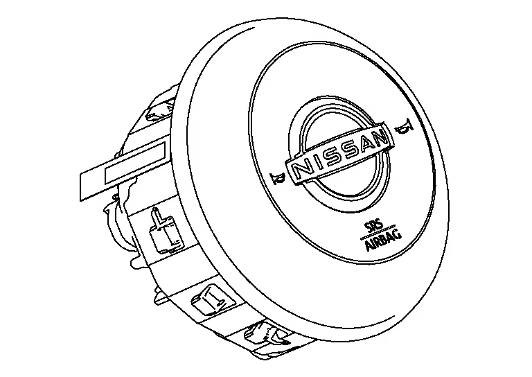
Driver Air Bag Module

The driver air bag module is dual stage and located in the steering wheel assembly. It operates with the SRS system in a frontal collision exceeding a specified level.
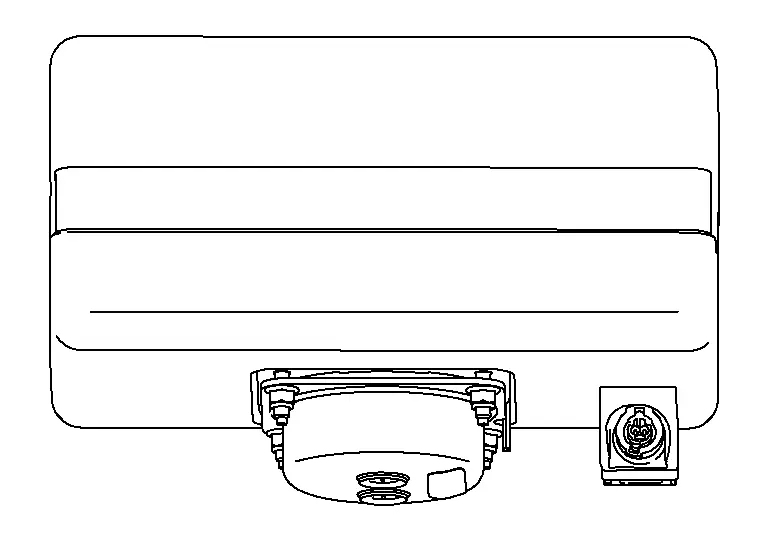
Front Passenger Air Bag Module

The front passenger air bag module is dual stage and is located behind the instrument panel assembly. It operates with the SRS system in a frontal collision exceeding a specified level. Refer to System Description for more information.
Front Center Air Bag Module

Front center air bag module is built into seat back inside of driver seat. Front center air bag module mainly consists of air bag and inflator which inflates air bag. Front center air bag is installed to seat back inside stitch of driver seat indicating that front center air bag is equipped. Front center air bag inflates through seat back inside stitch of drivers seat.
Front Side Air Bag Module

Front side air bag modules are built into the front seatback assemblies. Vehicles with side air bags are equipped with labels as shown.
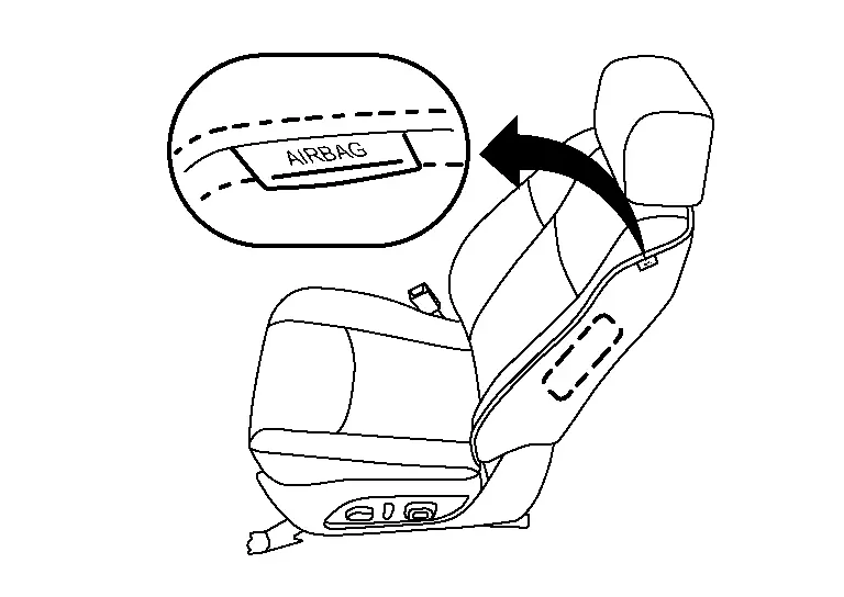
Rear Side Air Bag Module

Rear side air bag modules are built into the 2nd row seat back assemblies. Vehicles with side air bags are equipped with labels on the seat cushion outer finishers.
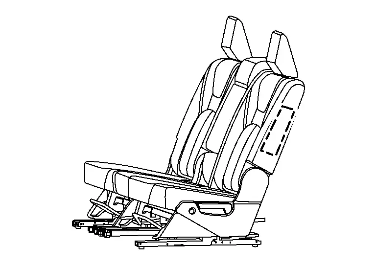
Side Curtain Air Bag Module

Side curtain air bag modules are located above the vehicle headlining. Vehicles with side curtain air bags are equipped with labels on the pillar upper finishers.
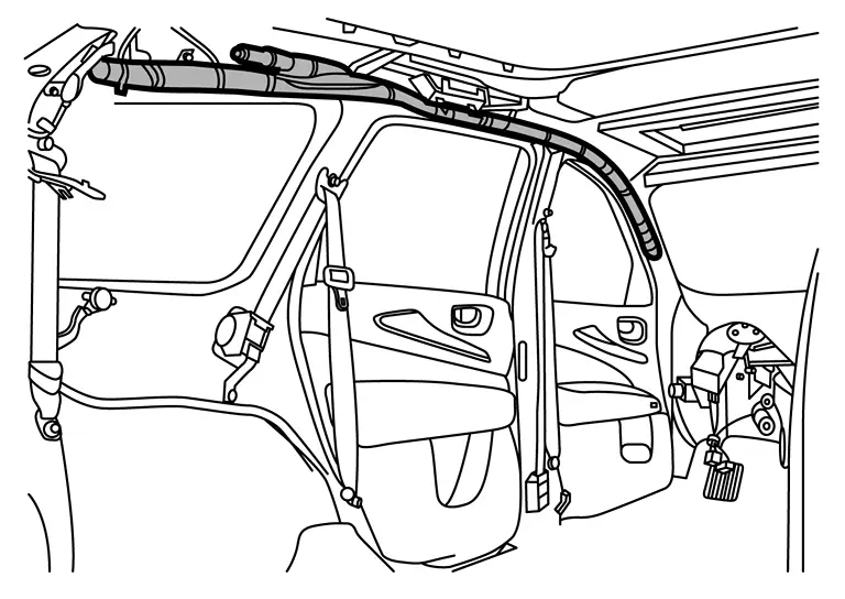
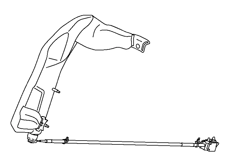
Front Seat Belt Pre-tensioner

The seat belt pre-tensioner system with load limiter is installed for both the driver's seat and the front passenger's seat. It operates simultaneously with the SRS air bag system in the event of a frontal collision with an impact exceeding a specified level.
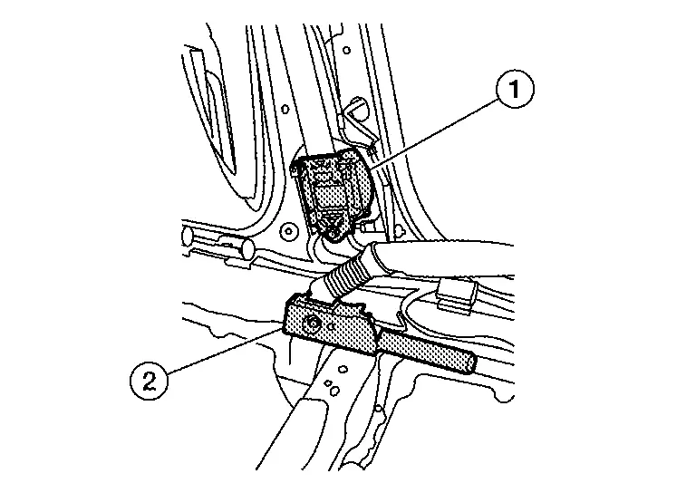
When the frontal collision with an impact exceeding a specified level occurs, seat belt slack resulting from clothing or other factors is immediately taken up by the pre-tensioner (1) as well as the lap pretensioner (2). Nissan Pathfinder Vehicle passengers are securely restrained.

When passengers in a vehicle are thrown forward in a collision and the restraining force of the seat belt exceeds a specified level, the load limiter permits the specified extension of the seat belt by the twisting of the ELR shaft, and a relaxation of the chest-area seat belt web tension while maintaining force.
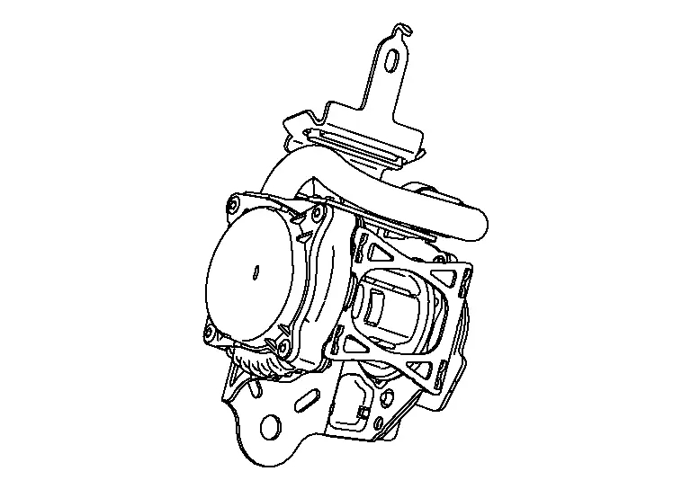
Rear Seat Belt Pre-tensioner

The seat belt pre-tensioner system with load limiter is installed for both the rear RH and LH. It operates simultaneously with the SRS air bag system in the event of a frontal collision with an impact exceeding a specified level.

When the frontal collision with an impact exceeding a specified level occurs, seat belt slack resulting from clothing or other factors is immediately taken up by the pre-tensioner Nissan Pathfinder Vehicle passengers are securely restrained.

When passengers in a vehicle are thrown forward in a collision and the restraining force of the seat belt exceeds a specified level, the load limiter permits the specified extension of the seat belt by the twisting of the ELR shaft, and a relaxation of the chest-area seat belt web tension while maintaining force.

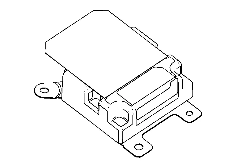
Air Bag Diagnosis Sensor Unit

The air bag diagnosis sensor unit is located under the center console assembly. The air bag diagnosis sensor unit receives signals from multiple SRS sensors and controls the deployment of the air bags. The deployment of the air bags depends on the type and severity of the collision. The air bag diagnosis sensor unit has self-diagnosis capability through the use of the CONSULT as well as flash codes displayed by the air bag warning lamp.
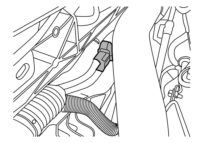
Crash Zone Sensor

The crash zone sensor is located behind the radiator and underneath the front air duct. The crash zone sensor sends signals to the air bag diagnosis sensor unit during a frontal collision. This sensor may be identified by a yellow connector.
Rear Side Air Bag Satellite Sensor

The rear side air bag satellite sensors are located behind the luggage side lower finisher LH and RH. The rear side air bag satellite sensors send signals to the air bag diagnosis sensor unit during a side collision. These sensors may be identified by yellow connectors.

Front Door Satellite Sensor

The front door satellite sensors are located in the driver and passenger doors. The front door satellite sensors send signals to the air bag diagnosis sensor unit during a side collision. These sensors may be identified by yellow connectors.
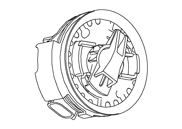
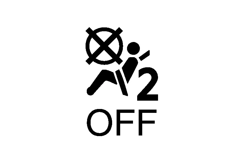
Front Passenger Air Bag Off Indicator

Front passenger air bag OFF indicator indicates whether or not passenger air bag is in the activation mode based on the judgment of the occupant detection system.
Diagnosis System (air Bag) Nissan Pathfinder SUV

Diagnosis Description

HOW TO PERFORM TROUBLE DIAGNOSES FOR QUICK AND ACCURATE REPAIR

  1. Obtain information about the symptom.

    • WHAT - vehicle model

    • WHEN - date, frequencies

    • WHERE - road conditions

    • HOW - operating conditions, symptoms, passengers

  2. Perform Preliminary Check.

    • Battery

    • Fuses

    • Harness connections

DIAGNOSIS METHODS

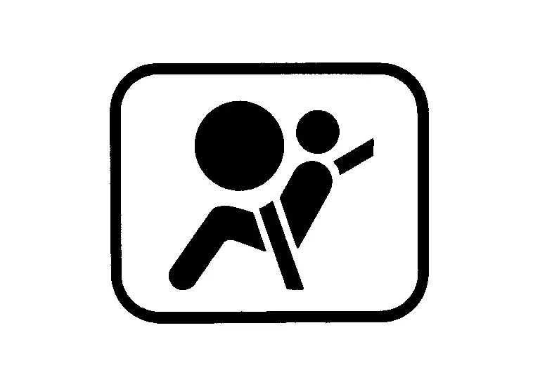
SRS self-diagnosis results can be read by using the AIR BAG warning lamp or CONSULT.

The User Mode is for the customer (driver). This mode warns the driver of a system malfunction through the AIR BAG warning lamp.

The Diagnosis Mode is for the technician. This mode helps the technician locate the malfunctioning circuit or part.

User Mode Diagnosis Mode Display type
AIR BAG warning lamp X X ON/OFF
CONSULT — X Monitoring

SRS Operation Check

USER MODE

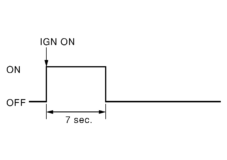
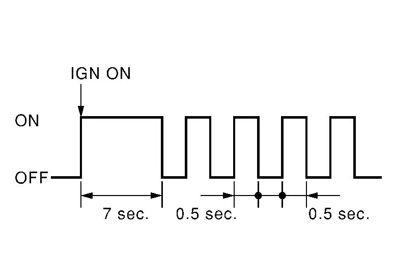
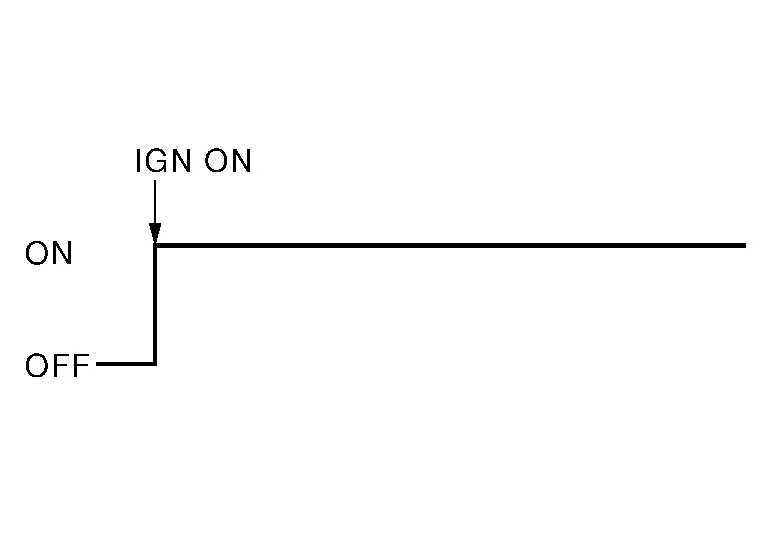
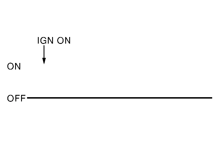
  1. Press the push-button ignition switch from OFF to ON and check that the air bag warning lamp blinks.

  2. Compare the blinking pattern with the examples in the table.
Air bag warning lamp flashing pattern (User Mode)
Warning lampSRS conditionReference item
  • No malfunction is detected.

  • No further action is necessary.

—
The system is malfunctioning and needs to be repaired. Refer to Trouble Diagnosis with CONSULT or Trouble Diagnosis without CONSULT.
Zero point reset is incomplete Refer to Special Repair Requirement.
  • Air bag is deployed.

  • Seat belt pre-tensioner is deployed.

Refer to For Frontal Collision or For Side and Rollover Collision.
  • Air bag diagnosis sensor unit is malfunctioning.

  • Air bag power supply circuit is malfunctioning.

  • SRS air bag warning lamp circuit is malfunctioning.

Refer to AIR BAG Warning Lamp Does Not Turn Off.
  • Air bag diagnosis sensor unit is malfunctioning.

  • Air bag warning lamp circuit is malfunctioning.

Refer to AIR BAG Warning Lamp Does Not Turn On.

Trouble Diagnosis with CONSULT

  1. Connect CONSULT.

  2. DTC is displayed on SELF-DIAG RESULTS.

  • SELF-DIAG [PAST] memory might not be erased. Refer to SRS Final Check.

  • SRS system malfunctions intermittently. Refer to Inspection Procedure.

Trouble Diagnosis without CONSULT

DIAGNOSIS MODE

  1. Ignition switch ON.

  2. After AIR BAG warning lamp lights for 7 seconds, ignition switch OFF within 1 second.

  3. Wait more than 3 seconds.

  4. Repeat steps 1 to 3 two more times (3 times total).

  5. Ignition switch ON.

SRS is now in Diagnosis Mode. Refer to Flash Code Index.

SRS History Check

SRS HISTORY CHECK

  1. Check repair history of the SRS. If no repairs have been made, perform SRS Operation Check. If repairs have been made, GO TO step 2.

  2. Erase "SELF-DIAG [PAST]" after repair. Refer to SRS Final Check.

SRS Final Check

DIAGNOSIS MODE

  1. Connect CONSULT.

  2. Confirm that zero point reset of OCS is complete.

  3. If no DTCs are detected on “SELF-DIAG RESULTS [CURRENT]”, repair of SRS is completed. Go to step 4.

    If any DTCs are detected on “SELF-DIAG RESULTS [CURRENT]”, the malfunction has not been repaired completely or another malfunction is being detected. Perform SRS Operation Check again. Refer to SRS Operation Check.

  4. Touch “ERASE”.

  5. Check that no malfunction is detected in “SELF-DIAG [PAST]”.

  6. Exit Diagnosis Mode and disconnect the CONSULT.

  7. Perform SRS Operation Check. Refer to SRS Operation Check.

CONSULT Function (AIR BAG)

CONSULT can display each diagnostic item using the diagnostic test modes shown following.

Diagnostic Test ModeDiagnostic ItemDescription
Self Diagnostic Result SELF-DIAG RESULT [CURRENT] A current Self-diagnosis result (also indicated by the number of warning lamp flashes in the Diagnosis mode) is displayed on the CONSULT screen in real time. This refers to a malfunctioning part requiring repairs.
Data Monitor DATA MONITOR Displays air bag diagnosis sensor unit input/output data in real time.
ECU Identification ECU DISCRIMINATED NO. Air bag diagnosis sensor unit ECU discriminated number (identification number) or part number is displayed. Air bag diagnosis sensor unit has individual ECU discriminated number (identification number) or part number based on model and equipment.
Trouble Diagnostic Record TROUBLE DIAG RECORD [PAST] With TROUBLE DIAG RECORD, diagnosis results previously erased by a reset operation can be displayed on the CONSULT screen.

CONSULT Function (OCCUPANT DETECTION)

WORK SUPPORT

CONSULT can display each diagnostic item using the diagnostic test modes shown following.

Diagnostic ItemDescription
Zero point reset function Perform zero point reset. Refer to Special Repair Requirement.

DATA MONITOR

Monitor ItemContents

Buckle Switch Status

[Not Moni/Unfasten/Fasten/Reload]

The switch status input from seat belt buckle switch (passenger side).

  • Not Moni: Seat belt buckle switch (passenger side) is not monitored.

  • Unfasten: Seat belt buckle switch (passenger side) is unfasten.

  • Fasten: Seat belt buckle switch (passenger side) is fasten.

  • Reload: The seat belt buckle switch (passenger side) state is loading.

Buckle Switch Spec

[Not Moni/Nor Op/Nor Cl/Frm ACU]

Displays the spec of the seat belt buckle switch (passenger side).

  • Not Moni: Seat belt buckle switch (passenger side) is not monitored.

  • Nor Op: Seat belt buckle switch (passenger side) is normal open type.

  • Nor Cl: Seat belt buckle switch (passenger side) is normal close type.

  • Frm ACU: Occupant detection system control unit receives seat belt buckle switch (passenger side) signal from air bag diagnosis sensor unit.

Buckle Switch Status (Comm)

[Not Moni/Moni(wir)/Frm ACU]

Displays the status of the seat belt buckle switch (passenger side) signal.

  • Not Moni: Seat belt buckle switch (passenger side) is not monitored.

  • Moni(wir): The switch status input from seat belt buckle switch (passenger side).

  • Frm ACU: The switch status input from air bag diagnosis sensor unit.