Power Control System - Dtc/circuit Diagnosis
- B2fac-12 Accessory Relay
- B2fac-14 Accessory Relay
- B2fae-12 Ignition Relay-1
- B2fae-14 Ignition Relay-1
- Push-Button Ignition Switch Circuit
- Accessory Relay
- Ignition Relay-1
- Power Supply and Ground Circuit
B2fac-12 Accessory Relay Nissan Pathfinder 2026
DTC Description
DTC DETECTION LOGIC
| DTC No. | CONSULT screen items (Trouble diagnosis content) | DTC detection condition | |
|---|---|---|---|
| B2FAC-12 | Accessory relay (Accessory relay) |
Diagnosis condition | When ignition switch is ON |
| Signal (terminal) | Accessory relay control signal (terminal #34) | ||
| Threshold | 16 V or more | ||
| Diagnosis delay time | 1 second or more | ||
POSSIBLE CAUSE
Harness or connectors (accessory relay control signal circuit is shorted to battery)
Accessory relay
BCM
FAIL-SAFE
—
DTC Confirmation Procedure
PERFORM DTC CONFIRMATION PROCEDURE
 CONSULT
Ignition switch ON.
Ignition switch OFF and wait for 1 minute with the front LH door opened.
Ignition switch ON.
Select “Self Diagnostic Result” mode of “BCM”.
Is DTC detected?
YES>>Refer to DTC Diagnosis Procedure.
NO>>To check malfunction symptom before repair: Refer to Intermittent Incident.
NO>>Confirmation after repair: Inspection End.
DTC Diagnosis Procedure
CHECK ACCESSORY RELAY CONTROL SIGNAL CIRCUIT (SHORT TO BATTERY)
Ignition switch OFF.
Disconnect accessory relay connector.
Disconnect BCM connector.
Check voltage between BCM harness connector and ground.
+ - Voltage
(Approx.)BCM Connector Terminal M18 34 Ground 0 V
Is the inspection result normal?
YES>>GO TO 2.
NO>>Repair or replace harness
CHECK ACCESSORY RELAY
Check accessory relay. Refer to Component Inspection.
Is the inspection result normal?
YES>>Replace BCM. Refer to Removal and Installation.
NO>>Replace accessory relay.
B2fac-14 Accessory Relay Nissan Pathfinder 2022
DTC Description
DTC DETECTION LOGIC
| DTC No. | CONSULT screen items (Trouble diagnosis content) | DTC detection condition | |
|---|---|---|---|
| B2FAC-14 | Accessory relay (Accessory relay) |
Diagnosis condition | When ignition switch is OFF (not auto ACC status) |
| Signal (terminal) | Accessory relay control signal (terminal #34) | ||
| Threshold | 0 V | ||
| Diagnosis delay time | 1 second or more | ||
POSSIBLE CAUSE
Harness or connectors (accessory relay control signal circuit is shorted to ground or open)
Accessory relay
BCM
FAIL-SAFE
—
DTC Confirmation Procedure
PERFORM DTC CONFIRMATION PROCEDURE
 CONSULT
Ignition switch ON.
Ignition switch OFF and wait for 1 minute with the front LH door opened.
Ignition switch ON.
Select “Self Diagnostic Result” mode of “BCM”.
Is DTC detected?
YES>>Refer to DTC Diagnosis Procedure.
NO>>To check malfunction symptom before repair: Refer to Intermittent Incident.
NO>>Confirmation after repair: Inspection End.
DTC Diagnosis Procedure
CHECK ACCESSORY RELAY CONTROL SIGNAL VOLTAGE
Ignition switch OFF.
Disconnect BCM connector.
Check voltage between BCM harness connector and ground.
+ - Voltage
(Approx.)BCM Connector Terminal M18 34 Ground Battery voltage
Is the inspection result normal?
YES>>Replace BCM. Refer to Removal and Installation.
NO>>GO TO 2.
CHECK ACCESSORY RELAY CONTROL SIGNAL CIRCUIT (OPEN)
Disconnect accessory relay connector.
Check continuity between BCM harness connector and accessory relay harness connector.
BCM Accessory relay Continuity Connector Terminal Connector Terminal M18 34 J-d 1 Yes
Is the inspection result normal?
YES>>GO TO 3.
NO>>Repair or replace harness.
CHECK ACCESSORY RELAY CONTROL SIGNAL CIRCUIT (SHORT TO GROUND)
Check continuity between BCM harness connector and ground.
| BCM | — | Continuity | |
|---|---|---|---|
| Connector | Terminal | ||
| M18 | 34 | Ground | No |
Is the inspection result normal?
YES>>GO TO 4.
NO>>Repair or replace harness.
CHECK ACCESSORY RELAY
Check accessory relay. Refer to Component Inspection.
Is the inspection result normal?
YES>>Inspection End.
NO>>Replace accessory relay.
B2fae-12 Ignition Relay-1 Nissan Pathfinder 2022
DTC Description
DTC DETECTION LOGIC
| DTC No. | CONSULT screen items (Trouble diagnosis content) | DTC detection condition | |
|---|---|---|---|
| B2FAE-12 | Ignition relay-1 (Ignition relay-1) |
Diagnosis condition | When ignition switch is ON |
| Signal (terminal) | Ignition relay-1 [fuse block (J/B)] control signal (terminal #105) | ||
| Threshold | 16 V or more | ||
| Diagnosis delay time | 1 second or more | ||
POSSIBLE CAUSE
Harness or connectors {ignition relay-1 [fuse block (J/B)] control signal circuit is shorted to battery}
Ignition relay-1
BCM
FAIL-SAFE
Inhibit engine cranking
DTC Confirmation Procedure
PERFORM DTC CONFIRMATION PROCEDURE
 CONSULT
Ignition switch ON.
Ignition switch OFF and wait for 1 second or more.
Ignition switch ON.
Select “Self Diagnostic Result” mode of “BCM”.
Is DTC detected?
YES>>Refer to DTC Diagnosis Procedure.
NO>>To check malfunction symptom before repair: Refer to Intermittent Incident.
NO>>Confirmation after repair: Inspection End.
DTC Diagnosis Procedure
CHECK IGNITION RELAY-1 [FUSE BLOCK (J/B)] CONTROL SIGNAL CIRCUIT (SHORT TO BATTERY)
Ignition switch OFF.
Disconnect BCM connector and ignition relay-1 connector.
Check voltage between BCM harness connector and ground.
+ - Voltage
(Approx.)BCM Connector Terminal M80 105 Ground 0 V
Is the inspection result normal?
YES>>GO TO 2.
NO>>Repair or replace harness.
CHECK IGNITION RELAY-1
Check ignition relay-1. Refer to Component Inspection.
Is the inspection result normal?
YES>>Replace BCM. Refer to Removal and Installation.
NO>>Replace ignition relay-1.
B2fae-14 Ignition Relay-1 Nissan Pathfinder R53
DTC Description
DTC DETECTION LOGIC
| DTC No. | CONSULT screen items (Trouble diagnosis content) | DTC detection condition | |
|---|---|---|---|
| B2FAE-14 | Ignition relay-1 (Ignition relay-1) |
Diagnosis condition | When ignition switch is OFF |
| Signal (terminal) | Ignition relay-1 [fuse block (J/B)] control signal (terminal #105) | ||
| Threshold | 0 V | ||
| Diagnosis delay time | 1 second or more | ||
POSSIBLE CAUSE
Harness or connectors {ignition relay-1 [fuse block (J/B)] control signal circuit is shorted to ground or open}
Ignition relay-1
BCM
FAIL-SAFE
Inhibit engine cranking
DTC Confirmation Procedure
PERFORM DTC CONFIRMATION PROCEDURE
 CONSULT
Ignition switch ON.
Ignition switch OFF and wait for 1 second or more.
Ignition switch ON.
Select “Self Diagnostic Result” mode of “BCM”.
Is DTC detected?
YES>>Refer to DTC Diagnosis Procedure.
NO>>To check malfunction symptom before repair: Refer to Intermittent Incident.
NO>>Confirmation after repair: Inspection End.
DTC Diagnosis Procedure
CHECK IGNITION RELAY-1 [FUSE BLOCK (J/B)] CONTROL SIGNAL VOLTAGE
Ignition switch OFF.
Disconnect BCM connector.
Check voltage between BCM harness connector and ground.
+ - Voltage
(Approx.)BCM Connector Terminal M80 105 Ground Battery voltage
Is the inspection result normal?
YES>>Replace BCM. Refer to Removal and Installation.
NO>>GO TO 2.
CHECK IGNITION RELAY-1 [FUSE BLOCK (J/B)] CONTROL SIGNAL CIRCUIT (OPEN)
Disconnect ignition relay-1 connector.
Check continuity between BCM harness connector and ignition relay-1 harness connector.
BCM Ignition relay-1 Continuity Connector Terminal Connector Terminal M80 105 J-d 2 Yes
Is the inspection result normal?
YES>>GO TO 3.
NO>>Repair or replace harness.
CHECK IGNITION RELAY-1 [FUSE BLOCK (J/B)] CONTROL SIGNAL CIRCUIT (SHORT TO GROUND)
Check continuity between BCM harness connector and ground.
| BCM | — | Continuity | |
|---|---|---|---|
| Connector | Terminal | ||
| M80 | 105 | Ground | No |
Is the inspection result normal?
YES>>GO TO 4.
NO>>Repair or replace harness.
CHECK IGNITION RELAY-1
Check ignition relay-1. Refer to Component Inspection.
Is the inspection result normal?
YES>>Inspection End
NO>>Replace ignition relay-1.
Push-Button Ignition Switch Circuit Nissan Pathfinder 5th Gen
Component Function Check
CHECK FUNCTION
 CONSULT
Ignition switch ON
Select “Push SW” in “Data Monitor” mode of “HANDS FREE MODULE”.
Check the push-button ignition switch signal under the following conditions:
| Test item | Condition | Status |
|---|---|---|
| Push SW | Push-button ignition switch is pressed | On |
| Push-button ignition switch is not pressed | Off |
Is the indication normal?
YES>>Inspection End.
NO>>Refer to Diagnosis Procedure.
Diagnosis Procedure
CHECK PUSH-BUTTON IGNITION SWITCH SIGNAL OUTPUT VOLTAGE
Ignition switch OFF.
Disconnect push-button ignition switch connector.
Check voltage between push-button ignition switch harness connector and ground.
+ - Voltage
(Approx.)Push-button ignition switch Connector Terminal M17 8 Ground Battery voltage
Is the inspection result normal?
YES>>GO TO 4.
NO>>GO TO 2.
CHECK PUSH-BUTTON IGNITION SWITCH SIGNAL CIRCUIT (OPEN)
Disconnect Intelligent Key unit connector.
Check continuity between push-button ignition switch harness connector and Intelligent Key unit harness connector.
Push-button ignition switch Intelligent Key unit Continuity Connector Terminal Connector Terminal M17 8 M38 9 Yes
Is the inspection result normal?
YES>>GO TO 3.
NO>>Repair the harness or connector.
CHECK PUSH-BUTTON IGNITION SWITCH SIGNAL CIRCUIT (SHORT TO GROUND)
Check continuity between push-button ignition switch harness connector and ground.
| Push-button ignition switch | — | Continuity | |
|---|---|---|---|
| Connector | Terminal | ||
| M17 | 8 | Ground | No |
Is the inspection result normal?
YES>>Replace Intelligent Key unit. Refer to Removal and Installation.
NO>>Repair the harness or connector.
CHECK PUSH-BUTTON IGNITION SWITCH GROUND CIRCUIT
Check continuity between push-button ignition switch harness connector and ground.
| Push-button ignition switch | — | Continuity | |
|---|---|---|---|
| Connector | Terminal | ||
| M17 | 4 | Ground | Yes |
Is the inspection result normal?
YES>>GO TO 5.
NO>>Repair the harness or connector.
CHECK PUSH-BUTTON IGNITION SWITCH
Check push-button ignition switch. Refer to Component Inspection.
Is the inspection result normal?
YES>>Inspection End.
NO>>Replace push-button ignition switch. Refer to Removal and Installation.
Component Inspection
CHECK PUSH-BUTTON IGNITION SWITCH
Ignition switch OFF.
Disconnect push-button ignition switch connector.
Check continuity between push-button ignition switch terminals.
Push-button ignition switch Condition Continuity Terminals 4 8 Pressed Yes Not pressed No
Is the inspection result normal?
YES>>Inspection End.
NO>>Replace push-button ignition switch. Refer to Removal and Installation.
Accessory Relay Nissan Pathfinder R53
Component Inspection
CHECK ACCESSORY RELAY
Ignition switch OFF.
Disconnect accessory relay connector.
Check continuity between accessory relay terminals.
| Accessory relay | Condition | Continuity | |
|---|---|---|---|
| Terminals | |||
 |
 |
12 V direct current supply between terminals  and  . |
Yes |
| No current supply | No | ||
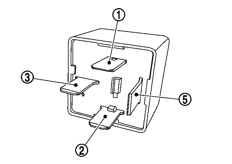
Is the inspection result normal?
YES>>Inspection End.
NO>>Replace accessory relay.
Ignition Relay-1 Nissan Pathfinder 5th Gen
Component Inspection
CHECK IGNITION RELAY-1
Ignition switch OFF.
Disconnect ignition relay-1 connector.
Check continuity between ignition relay-1 terminals.
| Ignition relay-1 | Condition | Continuity | |
|---|---|---|---|
| Terminals | |||
 |
 |
12 V direct current supply between terminals  and  . |
Yes |
| No current supply | No | ||
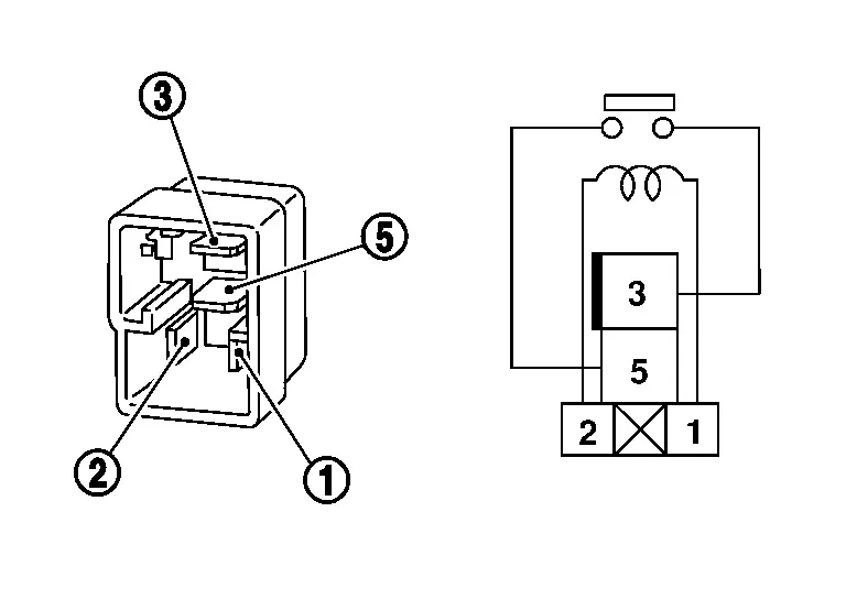
Is the inspection result normal?
YES>>Inspection End
NO>>Replace ignition relay-1.
Power Supply and Ground Circuit Nissan Pathfinder 2026
Ipdm E/r (intelligent Power Distribution Module Engine Room)
Diagnosis Procedure
CHECK FUSIBLE LINKS
Check that the following IPDM E/R fusible links are not blown:
| Terminal | Signal name | Fusible link Nos. | Capacity |
|---|---|---|---|
| 1 | Battery | H | 100 A |
| 2 | F | ||
| 81 | D | ||
| O | 40 A |
Is the fusible link blown?
YES>>Replace the blown fusible link after repairing the affected circuit.
NO>>GO TO 2
CHECK POWER SUPPLY CIRCUIT
Disconnect IPDM E/R connector.
Check voltage between IPDM E/R harness connector and ground.
IPDM E/R — Voltage
(Approx.)Connector Terminal E118 1 Ground Battery voltage 2 E77 81
Is the inspection result normal?
YES>>GO TO 3
NO>>Repair harness or connectors.
CHECK GROUND CIRCUIT
Ignition switch OFF.
Disconnect IPDM E/R connector.
Check continuity between IPDM E/R harness connector and ground.
| IPDM E/R | — | Continuity | |
|---|---|---|---|
| Connector | Terminal | ||
| E120 | 12 | Ground | Yes |
| E119 | 31 | ||
| E121 | 47 | ||
Is the inspection result normal?
YES>>Inspection End.
NO>>Repair harness or connectors.