System Description - System ++

In this manual: System Description - System ++
General Information — 8Engine :: Engine Mechanical — 19Engine Lubrication System - Precautions. Preparation — 1Engine Lubrication System - Lubrication System (System Description). Engine Oil Pressure (Basic Inspection). Service Data and Specifications (SDS) — 1Engine Cooling System - Precautions. Preparation. Service Data and Specifications (SDS) — 1Engine Cooling System - Engine Coolant — 1Engine Control System - System Description — 1System Description - Component Parts ++ — 1System Description - System ++ — 1Engine Control System - Ecu Diagnosis Information — 1Ecu Diagnosis Information - Ecm ++ — 1Engine Control System - Basic Inspection — 1Basic Inspection - Diagnosis and Repair Workflow ++ — 1Basic Inspection - Basic Inspection ++ — 1Basic Inspection - Additional Service When Replacing Ecm ++ — 1Basic Inspection - Fuel Pressure Check ++ — 1Basic Inspection - How to Set Srt Code ++ — 1Basic Inspection - How to Erase Permanent Dtc ++ — 1Engine Control System - Dtc/circuit Diagnosis — 1Engine Control System - Symptom Diagnosis — 1Engine Control System - Periodic Maintenance — 1Engine Control System - Removal and Installation — 1Fuel System - Precautions. Preparation. Service Data and Specifications (SDS) — 1Fuel System - Fuel System (Periodic Maintenance). Fuel Level Sensor Unit (Disassembly and Assembly) — 1Exhaust System - Precautions. Preparation — 1Exhaust System - Exhaust System (Periodic Maintenance). Exhaust System (Removal and Installation) — 1Starting System - Precautions. Preparation. Starter Motor (Service Data and Specifications (sds)) — 1Starting System - Diagnosis and Repair Work Flow — 1Starting System - Starting System (Symptom Diagnosis). Starter Motor (Removal and Installation) — 1Accelerator Control System - Precautions. Service Data and Specifications (SDS) — 1Accelerator Control System - Accelerator Pedal Assembly — 1Transmission & Driveline :: Transaxle & Transmission — 21Driveline - System Description — 1Transfer: Ty92b - Ecu Diagnosis Information. Awd Control Unit ++ — 1Driveline - Basic Inspection — 1Driveline - Dtc/circuit Diagnosis — 1Driveline - Symptom Diagnosis — 1Driveline - Removal and Installation — 1Transfer: Ty92b - Unit Removal and Installation. Transfer Assembly ++ — 1Driveline - Unit Disassembly and Assembly — 1Driveline - Basic Inspection — 1Driveline - Removal and Installation — 1Driveline - Unit Disassembly and Assembly — 1Front Axle - Precautions. Preparation — 1Front Axle - Noise, Vibration and Harshness (nvh) Troubleshooting (Symptom Diagnosis). Service Data and Specifications (SDS) — 1Front Axle - Front Drive Shaft Boot — 1Front Axle - Front Drive Shaft — 1Rear Axle - Precautions. Preparation. Service Data and Specifications (SDS) — 1Rear Axle - Noise, Vibration and Harshness (nvh) Troubleshooting — 1Rear Axle - Rear Drive Shaft — 1Suspension :: Front Suspension — 7Rear Suspension - Precautions. Preparation — 1Rear Suspension - Noise, Vibration and Harshness (nvh) Troubleshooting (Symptom Diagnosis). Service Data and Specifications (SDS) — 1Rear Suspension - Rear Suspension Assembly — 1Road Wheels & Tires - Precautions — 1Road Wheels & Tires - Preparation. Bcm (Ecu Diagnosis Information). Service Data and Specifications (SDS) — 1Road Wheels & Tires - System — 1Brakes :: Brake System — 9Parking Brake System - Precautions. Preparation — 1Parking Brake System - System — 1Vdc/tcs/abs - Precautions ++ — 1Brake Control System - System Description — 1System Description - Component Parts ++ — 1System Description - System ++ — 1Brake Control System - Basic Inspection — 1Brake Control System - Symptom Diagnosis — 1Brake Control System - Removal and Installation — 1Brake Control System - System Description — 1Brake Control System - Dtc/circuit Diagnosis — 1Brake Control System - Removal and Installation — 1Brake Control System - System Description — 1Brake Control System - Basic Inspection — 1Brake Control System - Symptom Diagnosis — 1Brake Control System - System Description — 1Brake Control System - Basic Inspection — 1Brake Control System - Symptom Diagnosis — 1Steering :: Steering System — 9Steering Control System - Precautions — 1Steering Control System - System — 1Steering Control System - Eps Control Unit (Ecu Diagnosis Information. Removal and Installation) — 1Restraints :: Seat Belt — 7Srs Air Bag - Precautions. Preparation — 1Srs Air Bag - Collision Diagnosis — 1Srs Air Bag - Occupant Classification System — 1Srs Air Bag Control System - Precautions — 1Srs Air Bag Control System - System — 1Srs Air Bag Control System - Diagnosis Sensor Unit — 1Srs Air Bag Control System - Inspection and Adjustment — 1Ventilation, Heater & Air Conditioner :: Ventilation System — 6Heater & Air Conditioning System - Precautions — 1Heater & Air Conditioning System - Preparation — 1Heater & Air Conditioning System - Component Parts — 1Heater & Air Conditioning System - Diagnosis and Repair Work Flow — 1Heater & Air Conditioning System - Compressor — 1Heater & Air Conditioning System - Cooler Pipe and Hose — 1Heater & Air Conditioning System - Condenser. Condenser — 1Heater & Air Conditioning System - Heating and Cooling Unit Assembly — 1Heater & Air Conditioning System - Service Data and Specifications (SDS) — 1Heater & Air Conditioning Control System - System Description — 1System Description - Component Parts ++ — 1System Description - System ++ — 1System Description - Operation ++ — 1Heater & Air Conditioning Control System - Ecu Diagnosis Information — 1Heater & Air Conditioning Control System - Basic Inspection — 1Heater & Air Conditioning Control System - Dtc/circuit Diagnosis — 1Heater & Air Conditioning Control System - Symptom Diagnosis — 1Heater & Air Conditioning Control System - Removal and Installation — 1Body Interior :: Interior — 8Instrument Panel - Precautions. Preparation. Clip List — 1Instrument Panel - Squeak and Rattle Trouble Diagnoses — 1Instrument Panel - Cluster Lid C — 1Seat - Precautions — 1Seat - Preparation. Clip List — 1Seat - Component Parts — 1Seat - System — 1Seat - Diagnosis and Repair Work Flow — 1Seat - Front Seat — 1Seat - Second Row Seats — 1Seat - Third Row Seats — 1Seat - Front Seat — 1Seat - Second Row Seat — 1Seat - Third Row Seat — 1Automatic Drive Positioner - Precautions. Preparation — 1Automatic Drive Positioner - System — 1Automatic Drive Positioner - Diagnosis and Repair Work Flow — 1Automatic Drive Positioner - Inspection and Adjustment — 1Body Exterior, Doors, Roof & Vehicle Security :: Door & Lock — 38Security Control System - Precautions — 1Security Control System - System — 1Security Control System - Ecm, Bcm, Intelligent Key Unit, Ipdm E/r — 1Security Control System - Vehicle Security System Cannot Be Set — 1Glass & Window System - Precautions. Preparation — 1Glass & Window System - Squeak and Rattle Trouble Diagnoses — 1Power Window Control System - Precautions. Preparation — 1Power Window Control System - Power Supply and Ground Circuit — 1Power Window Control System - Power Window Motor Circuit — 1Power Window Control System - Front Power Window Rh Alone Does Not Operate — 1Power Window Control System - Rear Lh Side Power Window Alone Does Not Operate — 1Power Window Control System - Rear Rh Side Power Window Alone Does Not Operate — 1Roof - Precautions. Preparation — 1Roof - Power Supply and Ground Circuit — 1Roof - Moonroof Switch Assembly — 1Roof - Lin Communication Circuit — 1Roof - Auto Operation Does Not Operate — 1Roof - Anti-Pinch Function Does Not Operate — 1Exterior - Precautions. Preparation. Clip List (Preparation) — 1Exterior - Squeak and Rattle Trouble Diagnoses — 1Exterior - Fender Protector — 1Exterior - Over Fender — 1Exterior - Under Cover — 1Exterior - Roof Side Rail — 1Body Repair - Service Information — 1Service Information - Sheet Metal Work ++ — 1Service Information - Body Welding and Precautions ++ — 1Service Information - Safety and Health ++ — 1Service Information - Repairing Procedures and Precautions ++ — 1Body Repair - Precaution — 1Body Repair - Preparation — 1Body Repair - Removal and Installation — 1Driver Controls :: Mirrors — 8Exterior Lighting System - System Description — 1System Description - Component Parts ++ — 1Exterior Lighting System - Basic Inspection — 1Exterior Lighting System - Dtc/circuit Diagnosis — 1Exterior Lighting System - Symptom Diagnosis — 1Exterior Lighting System - Periodic Maintenance — 1Exterior Lighting System - Removal and Installation — 1Interior Lighting System - Precautions. Preparation — 1Interior Lighting System - Component Parts. Interior Lighting System — 1Interior Lighting System - System — 1Interior Lighting System - Diagnosis and Repair Work Flow — 1Interior Lighting System - Interior Lighting System Symptoms (Symptom Diagnosis). Bcm (Ecu Diagnosis Information). Service Data and Specifications (SDS) — 1Interior Lighting System - Foot Lamp — 1Wiper & Washer - Precautions — 1Wiper & Washer - Preparation. Bcm, Ipdm E/r (Ecu Diagnosis Information). Service Data and Specifications (SDS) — 1Wiper & Washer - System — 1Wiper & Washer - Diagnosis and Repair Work Flow — 1Defogger - Precautions. Bcm, A/c Auto Amp. (Ecu Diagnosis Information) — 1Defogger - Diagnosis and Repair Work Flow — 1Horn - Precautions — 1Electrical & Power Control :: Power Outlet — 13Body Control System - Precautions. Preparation — 1Body Control System - Component Parts — 1Body Control System - System — 1Body Control System - Diagnosis System (bcm) — 1Body Control System - Bcm — 1Lan System - System Description — 1Lan System - System Description — 1Lan System - Dtc/circuit Diagnosis — 1Lan System - System Description — 1Lan System - Dtc/circuit Diagnosis — 1Power Control System - System Description — 1Power Control System - Basic Inspection — 1Power Control System - Dtc/circuit Diagnosis — 1Power Control System - System Description — 1Power Control System - Basic Inspection — 1Power Control System - Dtc/circuit Diagnosis — 1Power Control System - Removal and Installation — 1Charging System - Precautions. Preparation. Ecm, Ipdm E/r (Ecu Diagnosis Information) — 1Charging System - Diagnosis and Repair Work Flow — 1Charging System - Charging System (Symptom Diagnosis). Generator (Removal and Installation). Service Data and Specifications (SDS) — 1Power Supply, Ground & Circuit Elements - Precautions. Preparation. Service Data and Specifications (SDS) — 1Driver Information & Multimedia :: Meter, Warning Lamp & Indicator — 25Warning Chime System - Application Notice (How to Use This Manual). Precautions — 1Warning Chime System - System — 1Warning Chime System - Diagnosis System (combination Meter) — 1Warning Chime System - Bcm, Combination Meter (Ecu Diagnosis Information). Diagnosis and Repair Work Flow (Basic Inspection) — 1Sonar System - Precautions. Preparation — 1Sonar System - Sonar Control Unit — 1Dtc/circuit Diagnosis - B2720 Corner Sensor [rl] ++ — 1Audio, Visual & Navigation System - System Description — 1System Description - Component Parts ++ — 1System Description - System ++ — 1Audio, Visual & Navigation System - Ecu Diagnosis Information — 1Audio, Visual & Navigation System - Basic Inspection — 1Audio, Visual & Navigation System - Dtc/circuit Diagnosis — 1Dtc/circuit Diagnosis - Multi Av (av Control Unit) ++ — 1Audio, Visual & Navigation System - Symptom Diagnosis — 1Symptom Diagnosis - Multi Av System ++ — 1Audio, Visual & Navigation System - Removal and Installation — 1Audio, Visual & Navigation System - System Description — 1Audio, Visual & Navigation System - Ecu Diagnosis Information — 1Audio, Visual & Navigation System - Basic Inspection — 1Audio, Visual & Navigation System - Dtc/circuit Diagnosis — 1Audio, Visual & Navigation System - Symptom Diagnosis — 1Audio, Visual & Navigation System - Removal and Installation — 1Audio, Visual & Navigation System - System Description — 1Audio, Visual & Navigation System - Basic Inspection — 1Audio, Visual & Navigation System - Dtc/circuit Diagnosis — 1Audio, Visual & Navigation System - Symptom Diagnosis — 1Audio, Visual & Navigation System - Removal and Installation — 1Audio, Visual & Navigation System - System Description — 1Audio, Visual & Navigation System - Basic Inspection — 1Audio, Visual & Navigation System - Dtc/circuit Diagnosis — 1Audio, Visual & Navigation System - Symptom Diagnosis — 1Audio, Visual & Navigation System - Removal and Installation — 1Cruise Control & Driver Assistance :: Cruise Control System — 17Driver Assistance System - System Description — 1Driver Assistance System - Basic Inspection — 1Driver Assistance System - Dtc/circuit Diagnosis — 1Driver Assistance System - System Description — 1System Description - Component Parts ++ — 1System Description - System ++ — 1System Description - Operation ++ — 1System Description - Handling Precaution ++ — 1Driver Assistance System - Ecu Diagnosis Information — 1Driver Assistance System - Basic Inspection — 1Basic Inspection - Distance Sensor Alignment ++ — 1Basic Inspection - Camera Aiming Adjustment ++ — 1Basic Inspection - Action Test ++ — 1Driver Assistance System - Dtc/circuit Diagnosis — 1Dtc/circuit Diagnosis - Laser/radar (distance Sensor) ++ — 1Dtc/circuit Diagnosis - Lane Camera (front Camera Unit) ++ — 1Driver Assistance System - Symptom Diagnosis — 1Driver Assistance System - Removal and Installation — 1Driver Assistance System - System Description — 1System Description - System ++ — 1Driver Assistance System - Basic Inspection — 1Driver Assistance System - Dtc/circuit Diagnosis — 1Drive Mode System - Precautions — 1Drive Mode System - Component Parts. Drive Mode System — 1Drive Mode System - System — 1Drive Mode System - Diagnosis and Repair Work Flow — 1Drive Mode System - Drive Mode Select Switch Circuit — 1Maintenance - Precautions. Preparation — 1Maintenance - General Maintenance — 1Maintenance - Periodic Maintenance — 1Maintenance - Recommended Fluids and Lubricants — 1Maintenance - Engine Maintenance — 1Maintenance - Chassis and Body Maintenance — 1Engine Lubrication System - Periodic Maintenance — 1Engine Lubrication System - Removal and Installation — 1Engine Cooling System - System Description — 1Engine Cooling System - Removal and Installation — 1Engine Control System - Vq35dd — 1Fuel System - Removal and Installation — 1Starting System - System Description — 1Starting System - Dtc/circuit Diagnosis — 1Driveline - Transfer: Ty92b — 1Driveline - Rear Propeller Shaft: 3fcj-Cvj — 1Driveline - Rear Final Drive: R145 — 1Front Axle - Periodic Maintenance — 1Front Axle - Removal and Installation — 1Rear Axle - Periodic Maintenance — 1Rear Axle - Removal and Installation — 1Rear Suspension - Removal and Installation — 1Road Wheels & Tires - System Description — 1Road Wheels & Tires - Basic Inspection — 1Road Wheels & Tires - Dtc/circuit Diagnosis — 1Road Wheels & Tires - Symptom Diagnosis — 1Road Wheels & Tires - Periodic Maintenance — 1Road Wheels & Tires - Removal and Installation — 1Parking Brake System - System Description — 1Parking Brake System - Basic Inspection — 1Parking Brake System - Dtc/circuit Diagnosis — 1Parking Brake System - Symptom Diagnosis — 1Parking Brake System - Removal and Installation — 1Brake Control System - Vdc/tcs/abs — 1Brake Control System - Automatic Brake Hold — 1Brake Control System - Automatic Emergency Braking — 1Brake Control System - Rear Automatic Braking — 1Steering Control System - System Description — 1Steering Control System - Basic Inspection — 1Steering Control System - Dtc/circuit Diagnosis — 1Steering Control System - Symptom Diagnosis — 1Srs Air Bag - Removal and Installation — 1Srs Air Bag Control System - System Description — 1Srs Air Bag Control System - Basic Inspection — 1Srs Air Bag Control System - Symptom Diagnosis — 1Heater & Air Conditioning System - Symptom Diagnosis — 1Heater & Air Conditioning System - Periodic Maintenance — 1Heater & Air Conditioning Control System - Automatic Air Conditioning — 1Instrument Panel - Removal and Installation — 1Instrument Panel - Unit Disassembly and Assembly — 1Seat - Ecu Diagnosis Information — 1Seat - Dtc/circuit Diagnosis — 1Seat - Symptom Diagnosis — 1Automatic Drive Positioner - System Description — 1Automatic Drive Positioner - Ecu Diagnosis Information — 1Automatic Drive Positioner - Dtc/circuit Diagnosis — 1Automatic Drive Positioner - Symptom Diagnosis — 1Automatic Drive Positioner - Removal and Installation — 1Security Control System - System Description — 1Security Control System - Basic Inspection — 1Security Control System - Dtc/circuit Diagnosis — 1Security Control System - Symptom Diagnosis — 1Security Control System - Removal and Installation — 1Glass & Window System - Removal and Installation — 1Power Window Control System - System Description — 1Power Window Control System - Ecu Diagnosis Information — 1Power Window Control System - Basic Inspection — 1Power Window Control System - Dtc/circuit Diagnosis — 1Power Window Control System - Symptom Diagnosis — 1Power Window Control System - Removal and Installation — 1Roof - System Description — 1Roof - Ecu Diagnosis Information — 1Roof - Basic Inspection — 1Roof - Dtc/circuit Diagnosis — 1Roof - Symptom Diagnosis — 1Roof - Removal and Installation — 1Exterior - System Description — 1Exterior - Removal and Installation — 1Body Repair - Repair Information — 1Exterior Lighting System - Led Headlamp — 1Interior Lighting System - Dtc/circuit Diagnosis — 1Interior Lighting System - Removal and Installation — 1Wiper & Washer - System Description — 1Wiper & Washer - Dtc/circuit Diagnosis — 1Wiper & Washer - Symptom Diagnosis — 1Wiper & Washer - Removal and Installation — 1Defogger - System Description — 1Defogger - Dtc/circuit Diagnosis — 1Defogger - Symptom Diagnosis — 1Defogger - Removal and Installation — 1Horn - Removal and Installation — 1Body Control System - Basic Inspection — 1Body Control System - Dtc/circuit Diagnosis — 1Body Control System - Symptom Diagnosis — 1Body Control System - Removal and Installation — 1Lan System - Can Fundamental — 1Lan System - Can — 1Lan System - Can Gateway — 1Power Control System - Ipdm E/r — 1Power Control System - Power Distribution System — 1Charging System - System Description — 1Charging System - Dtc/circuit Diagnosis — 1Power Supply, Ground & Circuit Elements - System Description — 1Power Supply, Ground & Circuit Elements - Basic Inspection — 1Power Supply, Ground & Circuit Elements - Removal and Installation — 1Warning Chime System - System Description — 1Warning Chime System - Dtc/circuit Diagnosis — 1Warning Chime System - Symptom Diagnosis — 1Sonar System - System Description — 1Sonar System - Basic Inspection — 1Sonar System - Dtc/circuit Diagnosis — 1Sonar System - Symptom Diagnosis — 1Sonar System - Removal and Installation — 1Audio, Visual & Navigation System - Nissanconnect — 1Audio, Visual & Navigation System - Intelligent Around View Monitor System — 1Audio, Visual & Navigation System - Rear View Monitor System — 1Audio, Visual & Navigation System - Telematics System — 1Driver Assistance System - Adas Control Unit 2 — 1Driver Assistance System - Driver Assistance System — 1Driver Assistance System - Chassis Control — 1Drive Mode System - Removal and Installation — 1Dtc/circuit Diagnosis (C053c Wheel Speed Sensor ... U2141 Can Comm Circuit) — 1Dtc/circuit Diagnosis (P0011 Intake Valve Timing Control ... P0111 Iat Sensor) — 1Dtc/circuit Diagnosis (P0116 Engine Coolant Temperature Sensor ... P025b Fuel Pump Module a) — 1Dtc/circuit Diagnosis (P026b Injection Timing ... P0420 Three Way Catalyst Function) — 1Dtc/circuit Diagnosis (P0441 Evap Control System ... P0524 Engine Oil Pressure) — 1Dtc/circuit Diagnosis (P0532 A/c Refrigerant Pressure Sensor ... P064d Ecm) — 1Dtc/circuit Diagnosis (P06da Engine Oil Pressure Control Solenoid Valve ... P1217 Engine Over Temperature) — 1Dtc/circuit Diagnosis (P1220 Fuel Pump Control Module (fpcm) ... P1574 Ascd Vehicle Speed Sensor) — 1Dtc/circuit Diagnosis (P1575 Brake Switch ... P2101 Electric Throttle Control Function) — 1Dtc/circuit Diagnosis (P2118 Throttle Control Motor ... P34ac Electric Intake Valve Timing Control Actuator) — 1Dtc/circuit Diagnosis (Active Grille Shutter ... High Pressure Fuel Pump) — 1Dtc/circuit Diagnosis (Ignition Signal ... Variable Induction Air System) — 14012 C1040 Emergency Brake — 14013 C106a Wheel Sensor — 14014 C1078-55 Not Configuration — 14015 C10b4-98 Overheat — 14016 B1001 Lap Pre-Tensioner Lh — 14017 B0001 Driver Air Bag Module — 14018 B100e Knee Air Bag Module Rh — 14019 B142x Collision Detection — 1Dtc/circuit Diagnosis (B20c7-11 A/c Clutch ... B24a6-11 in-Vehicle Sensor) — 1Dtc/circuit Diagnosis (B24a6-15 in-Vehicle Sensor ... U2140-87 Can Comm Err (ecm)) — 1Dtc/circuit Diagnosis (C1f00-1c Control Unit ... C1f04-61 Brake Sw/stop Lamp Sw) — 1Dtc/circuit Diagnosis (C1f05-49 Front Camera Unit ... C1f70-87 Ethernet Circuit) — 1
~11min read

System Description

SYSTEM DIAGRAM — WITHOUT BOSE AUDIO SYSTEM

Except For Mexico
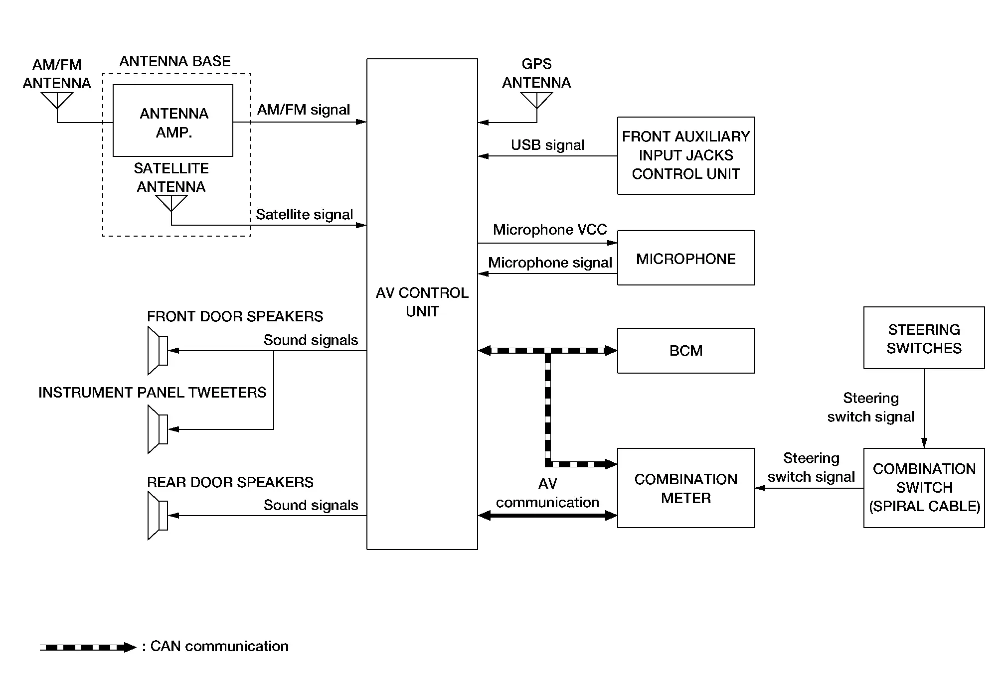
For Mexico

AV Control Unit Input Signal (AV Communication)

Transmit unit Signal name
Combination meter Steering switch signal

AV Control Unit Input Signal (CAN Communication)

Transmit unit Signal name
BCM Position light request signal
Combination meter
  • Nissan Pathfinder Vehicle speed signal

  • Parking brake status signal

SYSTEM DIAGRAM — WITH BOSE AUDIO SYSTEM

Except For Mexico

For Mexico

AV Control Unit Input Signal (AV Communication)

Transmit unit Signal name
Combination meter Steering switch signal

AV Control Unit Input Signal (CAN Communication)

Transmit unit Signal name
BCM Position light request signal
Combination meter
  • Nissan Pathfinder Vehicle speed signal

  • Parking brake status signal

Bose Speaker Amp. Input Signal (CAN Communication)

Transmit unit Signal name
ABS actuator and electric unit (control unit) Odometer signal
BCM Sleep wake up signal
IPDM E/R Battery voltage signal

AUDIO SYSTEM

Without Bose Audio System

Except For Mexico

The audio system consists of the following components:

  • AV control unit

  • Instrument panel tweeters

  • Front door speakers

  • Rear door speakers

  • Microphone

  • Front auxiliary input jacks

  • Steering switches

  • Combination meter

  • Combination switch (spiral cable)

  • GPS antenna

  • Antenna base (satellite antenna and antenna amp.)

When the audio system is on:

  • AM/FM signals received by the antenna base are amplified by the antenna amp. and sent to the AV control unit. The AV control unit sends the audio signals to the speakers.

  • Satellite signals received by the antenna base (satellite antenna) are sent to the AV control unit. The AV control unit sends the audio signals to the speakers.

For Mexico

The audio system consists of the following components:

  • AV control unit

  • Instrument panel tweeters

  • Front door speakers

  • Rear door speakers

  • Microphone

  • Front auxiliary input jacks

  • Steering switches

  • Combination meter

  • Combination switch (spiral cable)

  • GPS antenna

  • Antenna base (antenna amp.)

  • Glass antenna (FM sub)

When the audio system is on:

  • AM/FM signals received by the antenna base are amplified by the antenna amp. and sent to the AV control unit. The AV control unit sends the audio signals to the speakers.

  • The glass antenna (FM sub) receives radio signals and outputs them to the AV control unit. The AV control unit sends the audio signals to the speakers.

Refer to Owner's Manual for audio system operating instructions.

With Bose Audio System

Except For Mexico

The audio system consists of the following components:

  • AV control unit

  • Bose speaker amp.

  • Instrument panel tweeters

  • Center speaker

  • Front tweeters

  • Front door speakers

  • Rear door speakers

  • Rear side speakers

  • Subwoofer

  • Front auxiliary input jacks

  • Steering switches

  • Combination meter

  • Combination switch (spiral cable)

  • GPS antenna

  • Antenna base (satellite antenna and antenna amp.)

When the audio system is on:

  • AM/FM signals received by the antenna base are amplified by the antenna amp. and sent to the AV control unit. The AV control unit sends the audio signals to the Bose speaker amp. The Bose speaker amp. then sends the audio signals to the speakers.

  • Satellite signals received by the antenna base (satellite antenna) are sent to the AV control unit. The AV control unit sends the audio signals to the Bose speaker amp. The Bose speaker amp. then sends the audio signals to the speakers.

For Mexico

The audio system consists of the following components:

  • AV control unit

  • Bose speaker amp.

  • Instrument panel tweeters

  • Center speaker

  • Front tweeters

  • Front door speakers

  • Rear door speakers

  • Rear side speakers

  • Subwoofer

  • Front auxiliary input jacks

  • Steering switches

  • Combination meter

  • Combination switch (spiral cable)

  • GPS antenna

  • Antenna base (antenna amp.)

  • Glass antenna (FM sub)

When the audio system is on:

  • AM/FM signals received by the antenna base are amplified by the antenna amp. and sent to the AV control unit. The AV control unit sends the audio signals to the Bose speaker amp. The Bose speaker amp. then sends the audio signals to the speakers.

  • The glass antenna (FM sub) receives radio signals and outputs them to the AV control unit. The AV control unit sends the audio signals to the Bose speaker amp. The Bose speaker amp. then sends the audio signals to the speakers.

Refer to Owner's Manual for audio system operating instructions.

NAVIGATION SYSTEM

Description

  • The navigation system can be operated by control panel of the AV control unit and display (touch panel) of the AV control unit.

  • Guide sound during the operation of the navigation system is output from AV control unit to front tweeters.

  • AV control unit calculates the Nissan Pathfinder vehicle location based on the signals from GYRO (angle speed sensor), vehicle sensor, and GPS satellite, as well as the map data. The Nissan Pathfinder vehicle location is displayed on the AV control unit.

POSITION DETECTION PRINCIPLE

The navigation system periodically calculates the vehicle's current position according to the following three signals:

  • Travel distance of the vehicle as determined by the vehicle speed sensor

  • Turning angle of the Nissan Pathfinder vehicle as determined by the gyroscope (angular velocity sensor)

  • Direction of vehicle travel as determined by the GPS antenna (GPS information)

The current position of the vehicle is then identified by comparing the calculated vehicle position with map data (map-matching), and indicated on the screen as a Nissan Pathfinder vehicle mark. More accurate data is judged and used by comparing vehicle position detection results found by the GPS with the result by map-matching.

The current vehicle position will be calculated by detecting the distance the vehicle moved from the previous calculation point and its direction.
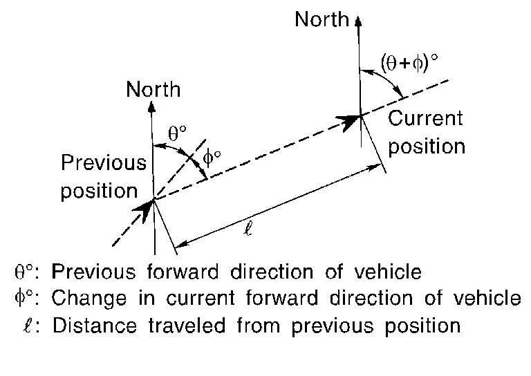
  • Travel distance

    Travel distance calculations are based on the vehicle speed sensor input signal. Therefore, the calculation may become incorrect as the tires wear down. To prevent this, an automatic distance correction function has been adopted.

  • Travel direction

    Change in the travel direction of the Nissan Pathfinder vehicle is calculated by a gyroscope (angular velocity sensor) and a GPS antenna (GPS information). They have both advantages and disadvantages.

    Type Advantage Disadvantage

    Gyroscope

    (angular velocity sensor)
    Can detect the Nissan Pathfinder vehicle's turning angle quite accurately. Direction errors may accumulate when Nissan Pathfinder vehicle is driven for long distances without stopping.

    GPS antenna

    (GPS information)
    Can detect the Nissan Pathfinder vehicle's travel direction (North/South/East/West). Correct direction cannot be detected when Nissan Pathfinder vehicle speed is low.

    More accurate traveling direction is detected because priorities are set for the signals from these two devices according to the situation.

MAP-MATCHING

Map-matching compares a current location detected by the method in the “Location Detection Principle” with road map data.
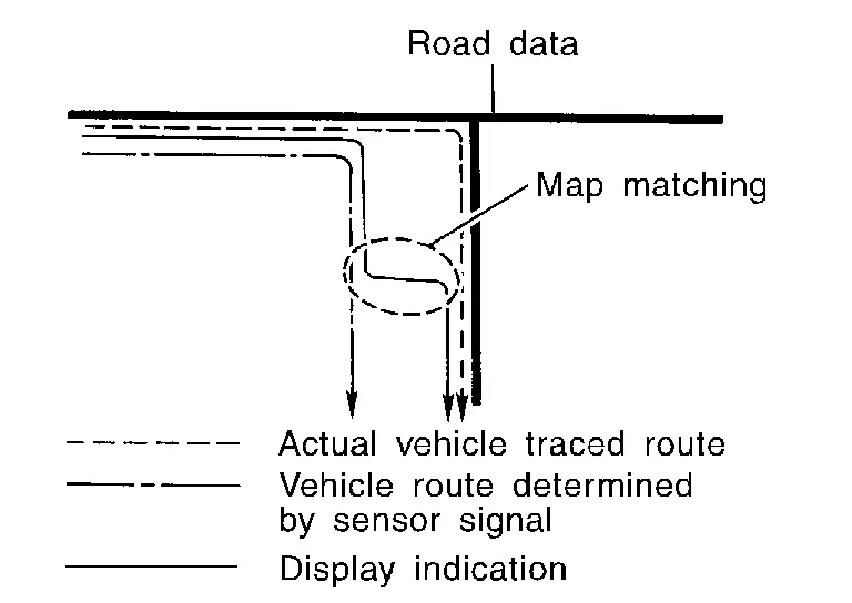
The vehicle position may not be corrected under the following circumstances and after driving for a certain time when GPS information is difficult to receive. In this case, the Nissan Pathfinder vehicle mark on the display must be corrected manually:

  • In map-matching, alternative routes to reach the destination will be shown and prioritized, after the road on which the Nissan Pathfinder vehicle is currently driving has been judged and the vehicle mark has been repositioned.

    Alternative routes will be shown in different order of priority, and the incorrect road can be avoided if there is an error in distance and/or direction.

    Routes are of the same priority if two roads are running in parallel. Therefore, the Nissan Pathfinder vehicle mark may appear on either of them alternately, depending on maneuvering of the steering wheel and configuration of the road.

  • Map-matching does not function correctly when a road on which the Nissan Pathfinder vehicle is driving is new and not recorded in the map data, or when road pattern stored in the map data and the actual road pattern are different due to repair.
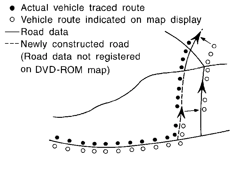
    The map-matching function may find another road and position the Nissan Pathfinder vehicle mark on it when driving on a road not present in the map. Then, the vehicle mark may change to it when the correct road is detected.

  • Effective range for comparing the Nissan Pathfinder vehicle position and travel direction calculated by the distance and direction with the road data read from the map data is limited. Therefore, correction by map-matching is not possible when there is an excessive gap between current Nissan Pathfinder vehicle position and the position on the map.

GPS (Global Positioning System)

GPS (Global Positioning System) is developed for and is controlled by the US Department of Defense. The system utilizes GPS satellites (NAVSTAR), transmitting out radio waves while flying on an orbit around the earth at an altitude of approximately 21,000 km (13,049 mile).
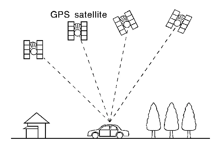
The receiver calculates the travel position in three dimensions (latitude/longitude/altitude) according to the time lag of the radio waves that four or more GPS satellites transmit (three-dimensional positioning). The GPS receiver calculates the travel position in two dimensions (latitude/longitude) with the previous altitude data if the GPS receiver receives only three radio waves (two-dimensional positioning). GPS position correction is not performed while stopping the Nissan Pathfinder vehicle.

Accuracy of the GPS will deteriorate under the following conditions:

  • In two-dimensional positioning, GPS accuracy will deteriorate when altitude of the vehicle position changes.

  • The position of GPS satellite affects GPS detection precision. The position detection may not be precisely performed.

  • The position detection is not performed if GPS receiver does not receive radio waves from GPS satellites. (Inside a tunnel, parking in a building, under an elevated highway etc.) GPS receiver may not receive radio waves from GPS satellites if any object is placed on the GPS antenna.

HANDS-FREE PHONE SYSTEM

System Operation

The Bluetooth® telephone system allows users who have a Bluetooth® cellular telephone to make a wireless connection between their cellular telephone and the AV control unit. Hands-free cellular telephone calls can be sent and received. Some Bluetooth® cellular telephones may not be recognized by the AV control unit. When a cellular telephone or the AV control unit is replaced, the telephone must be paired with the AV control unit. Different cellular telephones may have different pairing procedures, refer to the cellular telephone operating manual.

Refer to the Owner's Manual for Bluetooth® telephone system operating instructions.

AV Control Unit

When the ignition switch is turned ON, the AV control unit will power up. During power up, the AV control unit is initialized and performs various self-checks. Initialization may take up to 20 seconds.

Steering Switches

When buttons on the steering switches are pushed, the resistance in steering switch circuits change, depending on which button is pushed.

The following functions can be performed using the steering switches:

  • Initiate self-diagnosis of the Bluetooth® telephone system

  • Start a voice recognition session

  • Answer and end telephone calls

  • Adjust the volume of calls

  • Record memos

Microphone

  • The microphone is located in the roof in the map lamp assembly.

  • For vehicles without Bose audio system, the microphone sends a signal to the AV control unit.

  • For Nissan Pathfinder vehicles with Bose audio system, the microphone sends a signal to the TCU, the TCU sends the signal to the AV control unit.

SATELLITE RADIO FUNCTION

  • Satellite radio function is built into AV control unit.

  • Sound signal (satellite radio) is received by antenna base (satellite antenna) and transmitted to AV control unit. AV control unit outputs sound signal to each speaker.

FRONT AUXILIARY INPUT JACKS FUNCTION

  • For vehicles without Bose audio system, sound and data signals are transmitted from USB interfaces to the AV control unit and output to each speaker.

  • For Nissan Pathfinder vehicles with Bose audio system, sound and data signals are transmitted from USB interfaces to the AV control unit. The AV control unit sends the audio signals to the Bose speaker amp. The Bose speaker amp. then sends the audio signals to each speaker.

SPEED SENSITIVE VOLUME SYSTEM

  • Volume level of this system goes up and down automatically in proportion to the vehicle speed.

  • The control level can be selected by the customer.