Audio, Visual & Navigation System - Dtc/circuit Diagnosis
- B2e01 Internal Battery
- B2e04 Internal Battery
- B2e05 Air Bag Can
- B2e08 Microphone
- B2e0b Sos Led (auto)
- B2e0f Gps Antenna
- B2e12 Configuration
- B2e1b Automatic Ecall
- B2e32 Audio Unit
- B2e34 Tel Antenna
- B2e4f Bcm Pairing
- U0074 Av Communication
- U0079 Can Communication
- Power Supply and Ground Circuit
B2e01 Internal Battery Nissan Pathfinder
DTC Description
DTC DETECTION LOGIC
| DTC No. | CONSULT screen terms (Trouble diagnosis content) | DTC detection condition | |
|---|---|---|---|
| B2E01-16 | Internal battery (Internal battery) |
Diagnosis condition | When ignition switch is ON |
| Signal (terminal) | Internal battery remaining | ||
| Threshold | 25% or less | ||
| Diagnosis delay time | 1 second or more | ||
| B2E01-4A | Diagnosis condition | When ignition switch is ON | |
| Signal (terminal) | Internal battery power supply | ||
| Threshold | Internal battery degradation | ||
| Diagnosis delay time | 1 second or more | ||
| B2E01-4B | Diagnosis condition | When ignition switch is ON | |
| Signal (terminal) | Internal battery temperature | ||
| Threshold | 100 °C or more | ||
| Diagnosis delay time | 1 second or more | ||
| B2E01-96 | Diagnosis condition | When ignition switch is ON | |
| Signal (terminal) | Internal battery | ||
| Threshold | Internal battery abnormality | ||
| Diagnosis delay time | 1 second or more | ||
POSSIBLE CAUSE
16: Internal battery discharged
4A: Internal battery power supply approaching its end of life
4B: Internal battery temperature sensed above 100 °C
96:
Internal battery disconnected
Internal battery abnormality
Internal battery connector error
FAIL-SAFE
Telematics system does not operate
Confirmation Procedure
PERFORM DTC CONFIRMATION PROCEDURE
 CONSULT
Ignition switch ON.
Ignition switch OFF and wait at least 30 seconds.
Ignition switch ON and wait at least 30 seconds or more.
Select “Self Diagnostic Result” mode of “IVC”.
Check DTC.
Is DTC B2E01 detected?
YES>>Proceed to DTC Diagnosis Procedure.
NO>>To check malfunction symptom before repair: Refer to Intermittent Incident.
NO>>Confirmation after repair: Inspection End.
DTC Diagnosis Procedure
DETERMINE MALFUNCTION TYPE
 CONSULT
Ignition switch ON.
Ignition switch OFF and wait at least 30 seconds.
Ignition switch ON and wait at least 30 seconds or more.
Select “Self Diagnostic Result” mode of “IVC”.
Check DTC.
Is DTC B2E01–16, 4A, 4B or 96 detected?
YES>>16 – GO TO 2.
YES>>4A – GO TO 7.
YES>>4B – GO TO 3.
YES>>96 – GO TO 4.
NO>>Refer to Intermittent Incident.
INTERNAL BATTERY CHARGING
Ignition switch ON or engine idling more than one hour for internal battery charging of TCU.
YES>>GO TO 7.
DECREASE TCU TEMPERATURE
Move the Nissan Pathfinder vehicle to a cool place.
Ignition switch OFF and wait until the temperature around TCU cools down.
GO TO 7.
CHECK DTC STATUS
Check if DTC B2E01–96 is “CRNT” or “PAST”.
Is DTC B2E01–96 “CRNT”?
YES>>GO TO 5.
NO>>GO TO 7.
PERFORM WORK SUPPORT
 CONSULT
Perform “TCU Backup Battery Reset” in “Work support”.
YES>>GO TO 6.
PERFORM SELF DIAGNOSTIC RESULT
 CONSULT
Ignition switch ON.
Ignition switch OFF and wait at least 30 seconds.
Ignition switch ON and wait at least 30 seconds or more.
Select “Self Diagnostic Result” mode of “IVC”.
Check DTC.
Is DTC B2E01–96 CRNT detected again?
YES>>GO TO 7.
NO>>Inspection End.
PERFORM CONFIRMATION PROCEDURE AGAIN
 CONSULT
Ignition switch ON.
Erase DTC.
Perform DTC confirmation procedure again. Refer to Confirmation Procedure.
Is DTC B2E01–16, 4A, 4B or 96 detected again?
YES>>Replace TCU. Refer to Removal and Installation.
NO>>Inspection End.
B2e04 Internal Battery Nissan Pathfinder SUV
DTC Description
DTC DETECTION LOGIC
| DTC No. | CONSULT screen terms (Trouble diagnosis content) | DTC detection condition | |
|---|---|---|---|
| B2E04-16 | Internal battery (Internal battery) |
Diagnosis condition | When ignition switch is ON |
| Signal (terminal) | Internal battery remaining | ||
| Threshold | 25% or less | ||
| Diagnosis delay time | 1 second or more | ||
POSSIBLE CAUSE
Internal battery discharged
FAIL-SAFE
Telematics system does not operate
Confirmation Procedure
PERFORM DTC CONFIRMATION PROCEDURE
 CONSULT
Ignition switch ON.
Ignition switch OFF and wait at least 30 seconds.
Ignition switch ON and wait at least 30 seconds or more.
Select “Self Diagnostic Result” mode of “IVC”.
Check DTC.
Is DTC B2E04–16 detected?
YES>>Proceed to DTC Diagnosis Procedure.
NO>>To check malfunction symptom before repair: Refer to Intermittent Incident.
NO>>Confirmation after repair: Inspection End.
DTC Diagnosis Procedure
INTERNAL BATTERY CHARGING
Ignition switch ON or engine idling more than one hour for internal battery charging of TCU.
YES>>GO TO 2.
PERFORM CONFIRMATION PROCEDURE AGAIN
 CONSULT
Ignition switch ON.
Erase DTC.
Perform DTC confirmation procedure again. Refer to Confirmation Procedure.
Is DTC B2E04–16 detected again?
YES>>Replace TCU. Refer to Removal and Installation.
NO>>Inspection End.
B2e05 Air Bag Can Nissan Pathfinder Fifth generation
DTC Description
DTC DETECTION LOGIC
| DTC No. | CONSULT screen terms (Trouble diagnosis content) | DTC detection condition | |
|---|---|---|---|
| B2E05-29 | Air Bag (Air Bag CAN) |
Diagnosis condition | When ignition switch is ON |
| Signal (terminal) | CAN communication signal | ||
| Threshold | Transmission or reception error | ||
| Diagnosis delay time | 2 seconds or more | ||
POSSIBLE CAUSE
CAN communication system
FAIL-SAFE
Telematics system does not operate
Confirmation Procedure
PERFORM DTC CONFIRMATION PROCEDURE
 CONSULT
Ignition switch ON.
Ignition switch OFF and wait at least 30 seconds.
Ignition switch ON and wait at least 30 seconds or more.
Select “Self Diagnostic Result” mode of “IVC”.
Check DTC.
Is DTC B2E05–29 detected?
YES>>Proceed to DTC Diagnosis Procedure.
NO>>To check malfunction symptom before repair: Refer to Intermittent Incident.
NO>>Confirmation after repair: Inspection End.
DTC Diagnosis Procedure
PERFORM CAN COMMUNICATION TROUBLE DIAGNOSIS
Perform the trouble diagnosis for CAN communication system. Refer to Trouble Diagnosis Flow Chart.
Is the inspection result normal?
YES>>GO TO 2.
NO>>Repair or replace harness or connector.
CHECK THE AIR BAG DIAGNOSIS SENSOR UNIT
 CONSULT
Ignition switch ON.
Select “Self Diagnostic Result” mode of “AIR BAG”.
Check DTC.
Is any DTC detected?
YES>>Perform diagnosis on the detected DTC. Refer to DTC Index.
NO>>GO TO 3.
PERFORM CONFIRMATION PROCEDURE AGAIN
 CONSULT
Ignition switch ON.
Erase DTC.
Perform DTC confirmation procedure again. Refer to Confirmation Procedure.
Is DTC B2E05–29 detected again?
YES>>Replace TCU. Refer to Removal and Installation.
NO>>Inspection End.
B2e08 Microphone Nissan Pathfinder 5th Gen
DTC Description
DTC DETECTION LOGIC
| DTC No. | CONSULT screen terms (Trouble diagnosis content) | DTC detection condition | ||
|---|---|---|---|---|
| B2E08–01 | Microphone (Microphone) |
1 | Diagnosis condition | When ignition switch is ON. |
| Signal (terminal) | Microphone signal | |||
| Threshold | 7.2 V or more | |||
| Diagnosis delay time | 1 second or more | |||
| 2 | Diagnosis condition | When ignition switch is ON. | ||
| Signal (terminal) | Microphone signal | |||
| Threshold | 0.2 V or less | |||
| Diagnosis delay time | 1 second or more | |||
POSSIBLE CAUSE
Microphone signal circuit short to power supply
Microphone signal circuit short to ground
Microphone
FAIL-SAFE
Microphone does not operate
Confirmation Procedure
PERFORM DTC CONFIRMATION PROCEDURE
 CONSULT
Ignition switch ON.
Ignition switch OFF and wait at least 30 seconds.
Ignition switch ON and wait at least 30 seconds or more.
Select “Self Diagnostic Result” mode of “IVC”.
Check DTC.
Is DTC B2E08–01 detected?
YES>>Proceed to DTC Diagnosis Procedure.
NO>>To check malfunction symptom before repair: Refer to Intermittent Incident.
NO>>Confirmation after repair: Inspection End.
DTC Diagnosis Procedure
CHECK MICROPHONE SIGNAL CIRCUIT AND MICROPHONE VCC CIRCUIT CONTINUITY
Ignition switch OFF.
Disconnect TCU connector and microphone connector.
Check continuity between TCU connector and microphone connector.
TCU Microphone Continuity Connector Terminal Connector Terminal M188 17 R109 8 Yes 18 3 Check the continuity between TCU connector and ground.
TCU Ground Continuity Connector Terminal M188 17 No 18
Is the inspection result normal?
YES>>GO TO 2.
NO>>Repair or replace harness or connectors.
CHECK MICROPHONE VCC VOLTAGE
Connect TCU connector and microphone connector.
Ignition switch ON.
Check voltage between TCU connector and ground.
(+) (−) Voltage
(Approx.)TCU Connector Terminal M188 18 Ground 4.72 V
Is the inspection result normal?
YES>>GO TO 3.
NO>>Replace TCU. Refer to Removal and Installation.
CHECK MICROPHONE SIGNAL
Check signal between TCU connector and ground.
| (+) | (−) | Condition | Reference value | |
|---|---|---|---|---|
| TCU | ||||
| Connector | Terminal | |||
| M188 | 17 | Ground | Speak into microphone. | 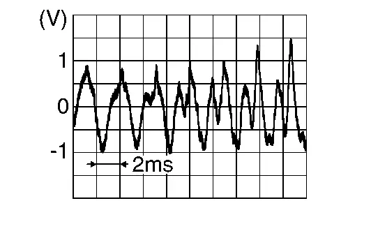 |
Is the inspection result normal?
YES>>Replace TCU. Refer to Removal and Installation.
NO>>Replace microphone. Refer to Removal and Installation.
B2e0b Sos Led (auto) Nissan Pathfinder SUV
DTC Description
DTC DETECTION LOGIC
| DTC No. | CONSULT screen terms (Trouble diagnosis content) | DTC detection condition | ||
|---|---|---|---|---|
| B2E0B-01 | SOS LED (Auto) [SOS LED (Auto)] |
1 | Diagnosis condition | When ignition switch is ON |
| Signal (terminal) | SOS switch LED (Green) signal (terminal 5) | |||
| Threshold | Not connected or open circuit | |||
| Diagnosis delay time | 1 second or more | |||
| 2 | Diagnosis condition | When ignition switch is ON | ||
| Signal (terminal) | SOS switch LED (Green) signal (terminal 5) | |||
| Threshold | 1.2 V or less | |||
| Diagnosis delay time | 1 second or more | |||
| 3 | Diagnosis condition | When ignition switch is ON | ||
| Signal (terminal) | SOS switch LED (Green) signal (terminal 5) | |||
| Threshold | 5.8 V or more | |||
| Diagnosis delay time | 1 second or more | |||
POSSIBLE CAUSE
Telematics switch is not connected,
SOS switch LED (Green) signal is open
SOS switch LED (Green) signal is short to ground
SOS switch LED (Green) signal is short to battery
FAIL-SAFE
Telematics system does not operate
Confirmation Procedure
PERFORM DTC CONFIRMATION PROCEDURE
 CONSULT
Ignition switch ON.
Ignition switch OFF and wait at least 30 seconds.
Ignition switch ON and wait at least 30 seconds or more.
Select “Self Diagnostic Result” mode of “IVC”.
Check DTC.
Is DTC B2E0B–01 detected?
YES>>Proceed to DTC Diagnosis Procedure.
NO>>To check malfunction symptom before repair: Refer to Intermittent Incident.
NO>>Confirmation after repair: Inspection End.
DTC Diagnosis Procedure
CHECK SOS SWITCH LED (GREEN) SIGNAL
Ignition switch ON.
Check the voltage between TCU connector and ground.
(+) (-) Condition Voltage
(Approx.)TCU Connector Terminal M188 5 Ground SOS switch LED (Green) not illuminated 4.0 V SOS switch LED (Green) illuminated 0 V
Is the inspection result normal?
YES>>GO TO 2.
NO>>Replace TCU. Refer to Removal and Installation.
CHECK SOS SWITCH LED (GREEN) SIGNAL CIRCUIT FOR OPEN
Ignition switch OFF.
Disconnect TCU connector and telematics switch connector.
Check the continuity between TCU connector and telematics switch connector.
TCU Telematics switch Continuity Connector Terminal Connector Terminal M188 5 R115 (without moonroof)
R108 (with moonroof)5 Yes
Is the inspection result normal?
YES>>GO TO 3.
NO>>Repair or replace harness or connector.
CHECK SOS SWITCH LED (GREEN) SIGNAL CIRCUIT FOR SHORT
Ignition switch ON.
Check the voltage between TCU connector and ground.
(+) (-) Voltage
(Approx.)TCU Connector Terminal M188 5 Ground 0 V
Is the inspection result normal?
YES>>GO TO 4.
NO>>Repair or replace harness or connector.
CHECK SOS SWITCH LED (GREEN) SIGNAL CIRCUIT FOR SHORT
Ignition switch OFF.
Check the continuity between TCU connector and ground.
| TCU | Ground | Continuity | |
| Connector | Terminal | ||
| M188 | 5 | No | |
Is the inspection result normal?
YES>>Replace telematics switch. Refer to Removal and Installation.
NO>>Repair or replace harness or connector.
B2e0f Gps Antenna Nissan Pathfinder 2026
DTC Description
DTC DETECTION LOGIC
| DTC No. | CONSULT screen terms (Trouble diagnosis content) | DTC detection condition | |
|---|---|---|---|
| B2E0F–06 | GPS antenna (GNSS COMMUNICATIONS FAILURE) |
Diagnosis condition | When receiving remote command |
| Signal (terminal) | — | ||
| Threshold | — | ||
| Diagnosis delay time | — | ||
POSSIBLE CAUSE
No service between server and TCU
FAIL-SAFE
Remote function does not operate
Confirmation Procedure
PERFORM DTC CONFIRMATION PROCEDURE
 CONSULT
Ignition switch ON.
Ignition switch OFF and wait at least 30 seconds.
Ignition switch ON and wait at least 30 seconds or more.
Select “Self Diagnostic Result” mode of “IVC”.
Check DTC.
Is DTC B2E0F–06 detected?
YES>>Proceed to DTC Diagnosis Procedure.
NO>>To check malfunction symptom before repair: Refer to Intermittent Incident.
NO>>Confirmation after repair: Inspection End.
DTC Diagnosis Procedure
PERFORM CONFIRMATION PROCEDURE AGAIN
 CONSULT
Ignition switch ON.
Erase DTC.
Perform DTC confirmation procedure again. Refer to Confirmation Procedure.
Is DTC B2E0F–06 detected again?
YES>>Replace TCU. Refer to Removal and Installation.
NO>>Inspection End.
B2e12 Configuration Nissan Pathfinder 2022
DTC Description
DTC DETECTION LOGIC
| DTC No. | CONSULT screen terms (Trouble diagnosis content) | DTC detection condition | |
|---|---|---|---|
| B2E12-55 | Configuration (Configuration) |
Diagnosis condition | When ignition switch is ON |
| Signal (terminal) | — | ||
| Threshold | Configuration not complete | ||
| Diagnosis delay time | 1 second or more | ||
POSSIBLE CAUSE
System configuration has not been made or is incomplete
TCU
FAIL-SAFE
TCU has not been initialized
Confirmation Procedure
PERFORM DTC CONFIRMATION PROCEDURE
 CONSULT
Ignition switch ON.
Ignition switch OFF and wait at least 30 seconds.
Ignition switch ON and wait at least 30 seconds or more.
Select “Self Diagnostic Result” mode of “IVC”.
Check DTC.
Is DTC B2E12–55 detected?
YES>>Proceed to DTC Diagnosis Procedure.
NO>>To check malfunction symptom before repair: Refer to Intermittent Incident.
NO>>Confirmation after repair: Inspection End.
DTC Diagnosis Procedure
PERFORM CONFIGURATION
When B2E12–55 is detected, perform configuration of TCU. Refer to Description.
>>GO TO 2.
PERFORM CONFIRMATION PROCEDURE AGAIN
 CONSULT
Ignition switch ON.
Erase DTC.
Perform confirmation procedure again. Refer to Confirmation Procedure.
Is DTC B2E12–55 detected?
YES>>Replace TCU. Refer to Removal and Installation.
NO>>Inspection End.
B2e1b Automatic Ecall Nissan Pathfinder R53
DTC Description
DTC DETECTION LOGIC
| DTC No. | CONSULT screen terms (Trouble diagnosis content) | DTC detection condition | |
|---|---|---|---|
| B2E1B–06 | Automatic eCall Locked (Automatic eCall Locked) |
Diagnosis condition | Ignition switch ON |
| Signal (terminal) | — | ||
| Threshold | Internal communication | ||
| Diagnosis delay time | More than 1 second | ||
| B2E1B–97 | Diagnosis condition | Ignition switch ON | |
| Signal (terminal) | — | ||
| Threshold | Automatic report function of the TCU is activated | ||
| Diagnosis delay time | 1 second or more | ||
POSSIBLE CAUSE
Failure type byte 06 – Internal communication
Failure type byte 97 – Automatic report function of the TCU is activated
FAIL-SAFE
Failure type byte 06 – Telematics system does not operate
Failure type byte 97 – Automatic emergency call does not operate
Confirmation Procedure
PERFORM DTC CONFIRMATION PROCEDURE
 CONSULT
Ignition switch ON.
Ignition switch OFF and wait at least 30 seconds.
Ignition switch ON and wait at least 30 seconds or more.
Select “Self Diagnostic Result” mode of “IVC”.
Check DTC.
Is DTC B2E1B detected?
YES>>Proceed to DTC Diagnosis Procedure.
NO>>To check malfunction symptom before repair: Refer to Intermittent Incident.
NO>>Confirmation after repair: Inspection End.
DTC Diagnosis Procedure
DETERMINE MALFUNCTION TYPE
 CONSULT
Ignition switch ON.
Ignition switch OFF and wait at least 30 seconds.
Ignition switch ON and wait at least 30 seconds or more.
Select “Self Diagnostic Result” mode of “IVC”.
Check the DTC.
Is DTC B2E1B–06 or 97 detected?
YES>>97 – GO TO 2.
YES>>06 – GO TO 3.
NO>>Refer to Intermittent Incident.
PERFORM AUTOMATIC REPORT PREVENTION RELEASE
Perform automatic report prevention release when DTC B2E1B-97 is detected.
YES>>Perform “Automatic report prevention release.” Refer to Work Procedure.
PERFORM CONFIRMATION PROCEDURE AGAIN
 CONSULT
Ignition switch ON.
Erase DTC.
Perform confirmation procedure again. Refer to Confirmation Procedure.
Is DTC B2E1B–06 detected again?
YES>>Replace TCU. Refer to Removal and Installation.
NO>>Inspection End.
B2e32 Audio Unit Nissan Pathfinder R53
DTC Description
DTC DETECTION LOGIC
| DTC No. | CONSULT screen terms (Trouble diagnosis content) | DTC detection condition | |
|---|---|---|---|
| B2E32-13 | Audio unit (Audio unit) |
Diagnosis condition | When ignition switch is ON |
| Signal (terminal) | Sound signal | ||
| Threshold | 3.7 V or less | ||
| Diagnosis delay time | 1 second or more | ||
| B2E32-11 | Diagnosis condition | When ignition switch is ON | |
| Signal (terminal) | Sound signal | ||
| Threshold | 0.5 V or less | ||
| Diagnosis delay time | 1 second or more | ||
| B2E32-12 | Diagnosis condition | When ignition switch is ON | |
| Signal (terminal) | Sound signal | ||
| Threshold | 5.0 V or more | ||
| Diagnosis delay time | 1 second or more | ||
POSSIBLE CAUSE
13: Sound signal circuit is open
11: Sound signal circuit is short to ground
12: Sound signal circuit is short to battery
AV control unit
FAIL-SAFE
Telematics sound is not output
Confirmation Procedure
PERFORM DTC CONFIRMATION PROCEDURE
 CONSULT
Ignition switch ON.
Ignition switch OFF and wait at least 30 seconds.
Ignition switch ON and wait at least 30 seconds or more.
Select “Self Diagnostic Result” mode of “IVC”.
Check DTC.
Is DTC B2E32 detected?
YES>>Proceed to DTC Diagnosis Procedure.
NO>>To check malfunction symptom before repair: Refer to Intermittent Incident.
NO>>Confirmation after repair: Inspection End.
DTC Diagnosis Procedure
DETERMINE MALFUNCTION TYPE
 CONSULT
Ignition switch ON.
Ignition switch OFF and wait at least 30 seconds.
Ignition switch ON and wait at least 30 seconds or more.
Select “Self Diagnostic Result” mode of “IVC”.
Check DTC.
Is DTC B2E32–11, 12 or 13 detected?
YES>>13 or 11 – GO TO 2.
YES>>12 – GO TO 3.
NO>>Refer to Intermittent Incident.
CHECK TEL VOICE SIGNAL CIRCUITS FOR OPEN OR SHORT TO GROUND
Ignition switch OFF.
Disconnect AV control unit and TCU connectors.
Check the continuity between AV control unit connector and TCU connector.
AV control unit TCU Continuity Connector Terminal Connector Terminal M123 (without Bose audio system)
M160 (with Bose audio system)32 M188 31 Yes 52 32 Check the continuity between AV control unit connector and ground.
AV control unit Continuity Connector Terminal Ground M123 (without Bose audio system)
M160 (with Bose audio system)32 — No 52
Is the inspection result normal?
YES>>GO TO 4.
NO>>Repair or replace harness or connectors.
CHECK TEL VOICE SIGNAL CIRCUIT FOR SHORT TO POWER SUPPLY
Ignition switch OFF.
Disconnect AV control unit connector and TCU connector.
Ignition switch ON.
Check the voltage between AV control unit connector and ground.
AV control unit Ground Voltage
Approx.Connector Terminal M123 (without Bose audio system)
M160 (with Bose audio system)32 — 0 V 52
Is the inspection result normal?
YES>>GO TO 4.
NO>>Repair or replace harness or connectors.
CHECK TEL VOICE SIGNAL
Connect AV control unit connector and TCU connector.
Ignition switch ON.
Check signal between the terminals of TCU connector.
TCU Condition Reference value Connector (+) (−) Terminal M188 31 32 Sound output 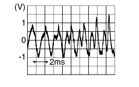
Is the inspection result normal?
YES>>Replace AV control unit. Refer to Removal and Installation.
NO>>Replace TCU. Refer to Removal and Installation.
B2e34 Tel Antenna Nissan Pathfinder Fifth generation
DTC Description
DTC DETECTION LOGIC
| DTC No. | CONSULT screen terms (Trouble diagnosis content) | DTC detection condition | |
|---|---|---|---|
| B2E34-13 | TEL antenna (Telephone antenna) |
Diagnosis condition | When ignition switch is ON |
| Signal (terminal) | TEL antenna signal | ||
| Threshold | Open circuit | ||
| Diagnosis delay time | 1 second or more | ||
| B2E34-11 | Diagnosis condition | When ignition switch is ON | |
| Signal (terminal) | TEL antenna signal | ||
| Threshold | Short to ground | ||
| Diagnosis delay time | 1 second or more | ||
| B2E34-12 | Diagnosis condition | When ignition switch is ON | |
| Signal (terminal) | TEL antenna signal | ||
| Threshold | Short to battery | ||
| Diagnosis delay time | 1 second or more | ||
POSSIBLE CAUSE
13: TEL antenna signal circuit is open
11: TEL antenna signal circuit is short to ground
12: TEL antenna signal circuit is short to battery
TEL antenna
FAIL-SAFE
Telematics can not send and receive via network
Confirmation Procedure
PERFORM DTC CONFIRMATION PROCEDURE
 CONSULT
Ignition switch ON.
Ignition switch OFF and wait at least 30 seconds.
Ignition switch ON and wait at least 30 seconds or more.
Select “Self Diagnostic Result” mode of “IVC”.
Check DTC.
Is DTC B2E34 detected?
YES>>Proceed to DTC Diagnosis Procedure.
NO>>To check malfunction symptom before repair: Refer to Intermittent Incident.
NO>>Confirmation after repair: Inspection End.
DTC Diagnosis Procedure
DETERMINE MALFUNCTION TYPE
 CONSULT
Ignition switch ON.
Ignition switch OFF and wait at least 30 seconds.
Ignition switch ON and wait at least 30 seconds or more.
Select “Self Diagnostic Result” mode of “IVC”.
Check DTC.
Is DTC B2E34–11, 12 or 13 detected?
YES>>13 – GO TO 2.
YES>>11 – GO TO 3.
YES>>12 – GO TO 4.
NO>>Refer to Intermittent Incident.
CHECK TEL ANTENNA HARNESS AND CONNECTOR
Ignition switch OFF.
Check the TEL antenna connector connection condition and the harness for damage.
Is the inspection result normal?
YES>>Replace TCU. Refer to Removal and Installation.
NO>>Replace telematics antenna. Refer to Removal and Installation.
CHECK TEL ANTENNA SIGNAL CIRCUIT FOR SHORT TO GROUND
Ignition switch OFF.
Disconnect TCU connector.
Check the continuity between TCU connector and ground.
TCU Continuity Connector Terminal Ground M154 47 — No 48
Is the inspection result normal?
YES>>Replace TCU. Refer to Removal and Installation.
NO>>Replace telematics antenna. Refer to Removal and Installation.
CHECK TEL ANTENNA SIGNAL CIRCUIT FOR SHORT TO POWER SUPPLY
Ignition switch OFF.
Disconnect TCU connector.
Ignition switch ON.
Check the voltage between TCU connector and ground.
TCU Ground Voltage
Approx.Connector Terminal M154 47 — 0 V 48
Is the inspection result normal?
YES>>Replace TCU. Refer to Removal and Installation.
NO>>Replace telematics antenna. Refer to Removal and Installation.
B2e4f Bcm Pairing Nissan Pathfinder Fifth generation
DTC Description
DTC DETECTION LOGIC
| DTC No. | CONSULT screen terms (Trouble diagnosis content) | DTC detection condition | |
|---|---|---|---|
| B2E4F-08 | BCM pairing (BCM pairing) |
Diagnosis condition | When ignition switch is ON |
| Signal (terminal) | BCM CAN signal | ||
| Threshold | — | ||
| Diagnosis delay time | — | ||
POSSIBLE CAUSE
After TCU replacement, Intelligent Key registration has not been performed
TCU-BCM pairing during Intelligent Key registration has not been performed
FAIL-SAFE
Remote engine start functions cannot be used
Confirmation Procedure
PERFORM DTC CONFIRMATION PROCEDURE
 CONSULT
Ignition switch ON.
Ignition switch OFF and wait at least 30 seconds.
Ignition switch ON and wait at least 30 seconds or more.
Select “Self Diagnostic Result” mode of “IVC”.
Check DTC.
Is DTC B2E4F–08 detected?
YES>>Proceed to DTC Diagnosis Procedure.
NO>>To check malfunction symptom before repair: Refer to Intermittent Incident.
NO>>Confirmation after repair: Inspection End.
DTC Diagnosis Procedure
RE-REGISTER INTELLIGENT KEYS
Re-register all Intelligent Keys. For initialization and registration of Intelligent Keys, refer to CONSULT Immobilizer mode and follow the on-screen instructions.
YES>>GO TO 2.
PERFORM SELF-DIAGNOSIS
 CONSULT
Erase ‘Self Diagnostic Result" mode of "IVC".
Ignition switch OFF –> ON.
Select ‘Self Diagnostic Result" mode of "IVC".
Check DTC.
Is DTC B2E4F–08 detected?
YES>>Replace TCU. Refer to Removal and Installation.
NO>>Inspection End.
U0074 Av Communication Nissan Pathfinder 2022
DTC Description
DTC DETECTION LOGIC
| DTC No. | CONSULT screen terms (Trouble diagnosis content) | DTC detection condition | |
|---|---|---|---|
| U0074-00 | AV communication (Control module communication bus B off) |
Diagnosis condition | When ignition switch is ON |
| Signal (terminal) | AV communication signal | ||
| Threshold | Transmission or reception error | ||
| Diagnosis delay time | 1 second or more | ||
POSSIBLE CAUSE
AV communication circuit
FAIL-SAFE
Telematics system does not operate
Confirmation Procedure
PERFORM DTC CONFIRMATION PROCEDURE
 CONSULT
Ignition switch ON.
Ignition switch OFF and wait at least 30 seconds.
Ignition switch ON and wait at least 30 seconds or more.
Select “Self Diagnostic Result” mode of “IVC”.
Check DTC.
Is DTC U0074–00 detected?
YES>>Proceed to DTC Diagnosis Procedure.
NO>>To check malfunction symptom before repair: Refer to Intermittent Incident.
NO>>Confirmation after repair: Inspection End.
DTC Diagnosis Procedure
CHECK TCU POWER SUPPLY AND GROUND CIRCUIT
Check TCU power supply and ground circuit. Refer to Diagnosis Procedure.
Is the inspection result normal?
YES>>GO TO 2.
NO>>Repair or replace malfunctioning parts.
CHECK AV COMMUNICATION CIRCUIT (1)
Ignition switch OFF.
Disconnect the following connectors:
AV control unit
Bose speaker amp.
Combination meter
TCU
Head up display unit
Check the continuity between AV control unit connector and TCU connector.
AV control unit TCU Continuity Connector Terminal Connector Terminal M123 (without Bose audio system)
M160 (with Bose audio system)22 M188 26 Yes 23 42 27 43
Is the inspection result normal?
YES>>GO TO 3.
NO>>Repair or replace harness or connector.
CHECK AV COMMUNICATION CIRCUIT (2)
Check the continuity between TCU connector terminals.
| TCU | Continuity | ||
|---|---|---|---|
| Connector | Terminal | ||
| M188 | 26 | 27 | No |
Is the inspection result normal?
YES>>Replace TCU. Refer to Removal and Installation.
NO>>Repair or replace harness or connector.
U0079 Can Communication Nissan Pathfinder
DTC Description
DESCRIPTION
CAN (Controller Area Network) is a serial communication line for real-time application. It is an on-Nissan Pathfinder vehicle multiplex communication line with high data communication speed and excellent error detection ability. Many electronic control units are equipped onto a Nissan Pathfinder vehicle, and each control unit shares information and links with other control units during operation (not independently). In CAN communication, control units are connected with 2 communication lines (CAN-High line, CAN-Low line) allowing a high rate of information transmission with less wiring. Each control unit transmits/receives data but selectively reads required data only. CAN Communication Signal Chart. Refer to CAN Communication Signal Chart.
DTC DETECTION LOGIC
| DTC No. | CONSULT screen terms (Trouble diagnosis content) | DTC detection condition | |
|---|---|---|---|
| U0079-00 | CAN communication (Control module communication bus G off) |
Diagnosis condition | When ignition switch is ON |
| Signal (terminal) | CAN communication signal | ||
| Threshold | Transmission or reception error | ||
| Diagnosis delay time | 2 seconds or more | ||
POSSIBLE CAUSE
CAN communication system
FAIL-SAFE
Telematics system does not operate
Confirmation Procedure
PERFORM DTC CONFIRMATION PROCEDURE
 CONSULT
Ignition switch ON.
Ignition switch OFF and wait at least 30 seconds.
Ignition switch ON and wait at least 30 seconds or more.
Select “Self Diagnostic Result” mode of “IVC”.
Check DTC.
Is DTC U0079–00 detected?
YES>>Proceed to DTC Diagnosis Procedure.
NO>>To check malfunction symptom before repair: Refer to Intermittent Incident.
NO>>Confirmation after repair: Inspection End.
DTC Diagnosis Procedure
PERFORM CONFIRMATION PROCEDURE AGAIN
 CONSULT
Ignition switch ON.
Erase DTC.
Perform DTC confirmation procedure again. Refer to Confirmation Procedure.
Is DTC U0079–00 detected again?
YES>>Replace TCU. Refer to Removal and Installation.
NO>>Inspection End.
Power Supply and Ground Circuit Nissan Pathfinder 2022
Diagnosis Procedure
CHECK FUSE
Check that the following fuse is not blown.
| Terminal No. | Signal name | Fuse No. | Capacity |
|---|---|---|---|
| 1 | Battery power supply | 17 | (10A) |
Are the fuses blown?
YES>>Replace the blown fuse after repairing the affected circuit.
NO>>GO TO 2.
CHECK POWER SUPPLY CIRCUIT
Ignition switch OFF.
Disconnect TCU connector .
Check voltage between TCU connector and ground.
TCU Ground Condition Voltage
(Approx.)Connector Terminal M188 1 — Ignition switch: OFF Battery voltage
Is the inspection result normal?
YES>>GO TO 3.
NO>>Repair or replace harness or connectors.
CHECK GROUND CIRCUIT
Ignition switch OFF.
Check continuity between TCU connector and ground.
TCU Ground Continuity Connector Terminal M188 28 — Yes 29
Is the inspection result normal?
YES>>Inspection End.
NO>>Repair or replace harness or connectors.