Driveline - Rear Final Drive: R145

In this manual: Driveline - Rear Final Drive: R145
General Information — 8Engine :: Engine Mechanical — 19Engine Lubrication System - Precautions. Preparation — 1Engine Lubrication System - Lubrication System (System Description). Engine Oil Pressure (Basic Inspection). Service Data and Specifications (SDS) — 1Engine Cooling System - Precautions. Preparation. Service Data and Specifications (SDS) — 1Engine Cooling System - Engine Coolant — 1Engine Control System - System Description — 1System Description - Component Parts ++ — 1System Description - System ++ — 1Engine Control System - Ecu Diagnosis Information — 1Ecu Diagnosis Information - Ecm ++ — 1Engine Control System - Basic Inspection — 1Basic Inspection - Diagnosis and Repair Workflow ++ — 1Basic Inspection - Basic Inspection ++ — 1Basic Inspection - Additional Service When Replacing Ecm ++ — 1Basic Inspection - Fuel Pressure Check ++ — 1Basic Inspection - How to Set Srt Code ++ — 1Basic Inspection - How to Erase Permanent Dtc ++ — 1Engine Control System - Dtc/circuit Diagnosis — 1Engine Control System - Symptom Diagnosis — 1Engine Control System - Periodic Maintenance — 1Engine Control System - Removal and Installation — 1Fuel System - Precautions. Preparation. Service Data and Specifications (SDS) — 1Fuel System - Fuel System (Periodic Maintenance). Fuel Level Sensor Unit (Disassembly and Assembly) — 1Exhaust System - Precautions. Preparation — 1Exhaust System - Exhaust System (Periodic Maintenance). Exhaust System (Removal and Installation) — 1Starting System - Precautions. Preparation. Starter Motor (Service Data and Specifications (sds)) — 1Starting System - Diagnosis and Repair Work Flow — 1Starting System - Starting System (Symptom Diagnosis). Starter Motor (Removal and Installation) — 1Accelerator Control System - Precautions. Service Data and Specifications (SDS) — 1Accelerator Control System - Accelerator Pedal Assembly — 1Transmission & Driveline :: Transaxle & Transmission — 21Driveline - System Description — 1Transfer: Ty92b - Ecu Diagnosis Information. Awd Control Unit ++ — 1Driveline - Basic Inspection — 1Driveline - Dtc/circuit Diagnosis — 1Driveline - Symptom Diagnosis — 1Driveline - Removal and Installation — 1Transfer: Ty92b - Unit Removal and Installation. Transfer Assembly ++ — 1Driveline - Unit Disassembly and Assembly — 1Driveline - Basic Inspection — 1Driveline - Removal and Installation — 1Driveline - Unit Disassembly and Assembly — 1Front Axle - Precautions. Preparation — 1Front Axle - Noise, Vibration and Harshness (nvh) Troubleshooting (Symptom Diagnosis). Service Data and Specifications (SDS) — 1Front Axle - Front Drive Shaft Boot — 1Front Axle - Front Drive Shaft — 1Rear Axle - Precautions. Preparation. Service Data and Specifications (SDS) — 1Rear Axle - Noise, Vibration and Harshness (nvh) Troubleshooting — 1Rear Axle - Rear Drive Shaft — 1Suspension :: Front Suspension — 7Rear Suspension - Precautions. Preparation — 1Rear Suspension - Noise, Vibration and Harshness (nvh) Troubleshooting (Symptom Diagnosis). Service Data and Specifications (SDS) — 1Rear Suspension - Rear Suspension Assembly — 1Road Wheels & Tires - Precautions — 1Road Wheels & Tires - Preparation. Bcm (Ecu Diagnosis Information). Service Data and Specifications (SDS) — 1Road Wheels & Tires - System — 1Brakes :: Brake System — 9Parking Brake System - Precautions. Preparation — 1Parking Brake System - System — 1Vdc/tcs/abs - Precautions ++ — 1Brake Control System - System Description — 1System Description - Component Parts ++ — 1System Description - System ++ — 1Brake Control System - Basic Inspection — 1Brake Control System - Symptom Diagnosis — 1Brake Control System - Removal and Installation — 1Brake Control System - System Description — 1Brake Control System - Dtc/circuit Diagnosis — 1Brake Control System - Removal and Installation — 1Brake Control System - System Description — 1Brake Control System - Basic Inspection — 1Brake Control System - Symptom Diagnosis — 1Brake Control System - System Description — 1Brake Control System - Basic Inspection — 1Brake Control System - Symptom Diagnosis — 1Steering :: Steering System — 9Steering Control System - Precautions — 1Steering Control System - System — 1Steering Control System - Eps Control Unit (Ecu Diagnosis Information. Removal and Installation) — 1Restraints :: Seat Belt — 7Srs Air Bag - Precautions. Preparation — 1Srs Air Bag - Collision Diagnosis — 1Srs Air Bag - Occupant Classification System — 1Srs Air Bag Control System - Precautions — 1Srs Air Bag Control System - System — 1Srs Air Bag Control System - Diagnosis Sensor Unit — 1Srs Air Bag Control System - Inspection and Adjustment — 1Ventilation, Heater & Air Conditioner :: Ventilation System — 6Heater & Air Conditioning System - Precautions — 1Heater & Air Conditioning System - Preparation — 1Heater & Air Conditioning System - Component Parts — 1Heater & Air Conditioning System - Diagnosis and Repair Work Flow — 1Heater & Air Conditioning System - Compressor — 1Heater & Air Conditioning System - Cooler Pipe and Hose — 1Heater & Air Conditioning System - Condenser. Condenser — 1Heater & Air Conditioning System - Heating and Cooling Unit Assembly — 1Heater & Air Conditioning System - Service Data and Specifications (SDS) — 1Heater & Air Conditioning Control System - System Description — 1System Description - Component Parts ++ — 1System Description - System ++ — 1System Description - Operation ++ — 1Heater & Air Conditioning Control System - Ecu Diagnosis Information — 1Heater & Air Conditioning Control System - Basic Inspection — 1Heater & Air Conditioning Control System - Dtc/circuit Diagnosis — 1Heater & Air Conditioning Control System - Symptom Diagnosis — 1Heater & Air Conditioning Control System - Removal and Installation — 1Body Interior :: Interior — 8Instrument Panel - Precautions. Preparation. Clip List — 1Instrument Panel - Squeak and Rattle Trouble Diagnoses — 1Instrument Panel - Cluster Lid C — 1Seat - Precautions — 1Seat - Preparation. Clip List — 1Seat - Component Parts — 1Seat - System — 1Seat - Diagnosis and Repair Work Flow — 1Seat - Front Seat — 1Seat - Second Row Seats — 1Seat - Third Row Seats — 1Seat - Front Seat — 1Seat - Second Row Seat — 1Seat - Third Row Seat — 1Automatic Drive Positioner - Precautions. Preparation — 1Automatic Drive Positioner - System — 1Automatic Drive Positioner - Diagnosis and Repair Work Flow — 1Automatic Drive Positioner - Inspection and Adjustment — 1Body Exterior, Doors, Roof & Vehicle Security :: Door & Lock — 38Security Control System - Precautions — 1Security Control System - System — 1Security Control System - Ecm, Bcm, Intelligent Key Unit, Ipdm E/r — 1Security Control System - Vehicle Security System Cannot Be Set — 1Glass & Window System - Precautions. Preparation — 1Glass & Window System - Squeak and Rattle Trouble Diagnoses — 1Power Window Control System - Precautions. Preparation — 1Power Window Control System - Power Supply and Ground Circuit — 1Power Window Control System - Power Window Motor Circuit — 1Power Window Control System - Front Power Window Rh Alone Does Not Operate — 1Power Window Control System - Rear Lh Side Power Window Alone Does Not Operate — 1Power Window Control System - Rear Rh Side Power Window Alone Does Not Operate — 1Roof - Precautions. Preparation — 1Roof - Power Supply and Ground Circuit — 1Roof - Moonroof Switch Assembly — 1Roof - Lin Communication Circuit — 1Roof - Auto Operation Does Not Operate — 1Roof - Anti-Pinch Function Does Not Operate — 1Exterior - Precautions. Preparation. Clip List (Preparation) — 1Exterior - Squeak and Rattle Trouble Diagnoses — 1Exterior - Fender Protector — 1Exterior - Over Fender — 1Exterior - Under Cover — 1Exterior - Roof Side Rail — 1Body Repair - Service Information — 1Service Information - Sheet Metal Work ++ — 1Service Information - Body Welding and Precautions ++ — 1Service Information - Safety and Health ++ — 1Service Information - Repairing Procedures and Precautions ++ — 1Body Repair - Precaution — 1Body Repair - Preparation — 1Body Repair - Removal and Installation — 1Driver Controls :: Mirrors — 8Exterior Lighting System - System Description — 1System Description - Component Parts ++ — 1Exterior Lighting System - Basic Inspection — 1Exterior Lighting System - Dtc/circuit Diagnosis — 1Exterior Lighting System - Symptom Diagnosis — 1Exterior Lighting System - Periodic Maintenance — 1Exterior Lighting System - Removal and Installation — 1Interior Lighting System - Precautions. Preparation — 1Interior Lighting System - Component Parts. Interior Lighting System — 1Interior Lighting System - System — 1Interior Lighting System - Diagnosis and Repair Work Flow — 1Interior Lighting System - Interior Lighting System Symptoms (Symptom Diagnosis). Bcm (Ecu Diagnosis Information). Service Data and Specifications (SDS) — 1Interior Lighting System - Foot Lamp — 1Wiper & Washer - Precautions — 1Wiper & Washer - Preparation. Bcm, Ipdm E/r (Ecu Diagnosis Information). Service Data and Specifications (SDS) — 1Wiper & Washer - System — 1Wiper & Washer - Diagnosis and Repair Work Flow — 1Defogger - Precautions. Bcm, A/c Auto Amp. (Ecu Diagnosis Information) — 1Defogger - Diagnosis and Repair Work Flow — 1Horn - Precautions — 1Electrical & Power Control :: Power Outlet — 13Body Control System - Precautions. Preparation — 1Body Control System - Component Parts — 1Body Control System - System — 1Body Control System - Diagnosis System (bcm) — 1Body Control System - Bcm — 1Lan System - System Description — 1Lan System - System Description — 1Lan System - Dtc/circuit Diagnosis — 1Lan System - System Description — 1Lan System - Dtc/circuit Diagnosis — 1Power Control System - System Description — 1Power Control System - Basic Inspection — 1Power Control System - Dtc/circuit Diagnosis — 1Power Control System - System Description — 1Power Control System - Basic Inspection — 1Power Control System - Dtc/circuit Diagnosis — 1Power Control System - Removal and Installation — 1Charging System - Precautions. Preparation. Ecm, Ipdm E/r (Ecu Diagnosis Information) — 1Charging System - Diagnosis and Repair Work Flow — 1Charging System - Charging System (Symptom Diagnosis). Generator (Removal and Installation). Service Data and Specifications (SDS) — 1Power Supply, Ground & Circuit Elements - Precautions. Preparation. Service Data and Specifications (SDS) — 1Driver Information & Multimedia :: Meter, Warning Lamp & Indicator — 25Warning Chime System - Application Notice (How to Use This Manual). Precautions — 1Warning Chime System - System — 1Warning Chime System - Diagnosis System (combination Meter) — 1Warning Chime System - Bcm, Combination Meter (Ecu Diagnosis Information). Diagnosis and Repair Work Flow (Basic Inspection) — 1Sonar System - Precautions. Preparation — 1Sonar System - Sonar Control Unit — 1Dtc/circuit Diagnosis - B2720 Corner Sensor [rl] ++ — 1Audio, Visual & Navigation System - System Description — 1System Description - Component Parts ++ — 1System Description - System ++ — 1Audio, Visual & Navigation System - Ecu Diagnosis Information — 1Audio, Visual & Navigation System - Basic Inspection — 1Audio, Visual & Navigation System - Dtc/circuit Diagnosis — 1Dtc/circuit Diagnosis - Multi Av (av Control Unit) ++ — 1Audio, Visual & Navigation System - Symptom Diagnosis — 1Symptom Diagnosis - Multi Av System ++ — 1Audio, Visual & Navigation System - Removal and Installation — 1Audio, Visual & Navigation System - System Description — 1Audio, Visual & Navigation System - Ecu Diagnosis Information — 1Audio, Visual & Navigation System - Basic Inspection — 1Audio, Visual & Navigation System - Dtc/circuit Diagnosis — 1Audio, Visual & Navigation System - Symptom Diagnosis — 1Audio, Visual & Navigation System - Removal and Installation — 1Audio, Visual & Navigation System - System Description — 1Audio, Visual & Navigation System - Basic Inspection — 1Audio, Visual & Navigation System - Dtc/circuit Diagnosis — 1Audio, Visual & Navigation System - Symptom Diagnosis — 1Audio, Visual & Navigation System - Removal and Installation — 1Audio, Visual & Navigation System - System Description — 1Audio, Visual & Navigation System - Basic Inspection — 1Audio, Visual & Navigation System - Dtc/circuit Diagnosis — 1Audio, Visual & Navigation System - Symptom Diagnosis — 1Audio, Visual & Navigation System - Removal and Installation — 1Cruise Control & Driver Assistance :: Cruise Control System — 17Driver Assistance System - System Description — 1Driver Assistance System - Basic Inspection — 1Driver Assistance System - Dtc/circuit Diagnosis — 1Driver Assistance System - System Description — 1System Description - Component Parts ++ — 1System Description - System ++ — 1System Description - Operation ++ — 1System Description - Handling Precaution ++ — 1Driver Assistance System - Ecu Diagnosis Information — 1Driver Assistance System - Basic Inspection — 1Basic Inspection - Distance Sensor Alignment ++ — 1Basic Inspection - Camera Aiming Adjustment ++ — 1Basic Inspection - Action Test ++ — 1Driver Assistance System - Dtc/circuit Diagnosis — 1Dtc/circuit Diagnosis - Laser/radar (distance Sensor) ++ — 1Dtc/circuit Diagnosis - Lane Camera (front Camera Unit) ++ — 1Driver Assistance System - Symptom Diagnosis — 1Driver Assistance System - Removal and Installation — 1Driver Assistance System - System Description — 1System Description - System ++ — 1Driver Assistance System - Basic Inspection — 1Driver Assistance System - Dtc/circuit Diagnosis — 1Drive Mode System - Precautions — 1Drive Mode System - Component Parts. Drive Mode System — 1Drive Mode System - System — 1Drive Mode System - Diagnosis and Repair Work Flow — 1Drive Mode System - Drive Mode Select Switch Circuit — 1Maintenance - Precautions. Preparation — 1Maintenance - General Maintenance — 1Maintenance - Periodic Maintenance — 1Maintenance - Recommended Fluids and Lubricants — 1Maintenance - Engine Maintenance — 1Maintenance - Chassis and Body Maintenance — 1Engine Lubrication System - Periodic Maintenance — 1Engine Lubrication System - Removal and Installation — 1Engine Cooling System - System Description — 1Engine Cooling System - Removal and Installation — 1Engine Control System - Vq35dd — 1Fuel System - Removal and Installation — 1Starting System - System Description — 1Starting System - Dtc/circuit Diagnosis — 1Driveline - Transfer: Ty92b — 1Driveline - Rear Propeller Shaft: 3fcj-Cvj — 1Driveline - Rear Final Drive: R145 — 1Front Axle - Periodic Maintenance — 1Front Axle - Removal and Installation — 1Rear Axle - Periodic Maintenance — 1Rear Axle - Removal and Installation — 1Rear Suspension - Removal and Installation — 1Road Wheels & Tires - System Description — 1Road Wheels & Tires - Basic Inspection — 1Road Wheels & Tires - Dtc/circuit Diagnosis — 1Road Wheels & Tires - Symptom Diagnosis — 1Road Wheels & Tires - Periodic Maintenance — 1Road Wheels & Tires - Removal and Installation — 1Parking Brake System - System Description — 1Parking Brake System - Basic Inspection — 1Parking Brake System - Dtc/circuit Diagnosis — 1Parking Brake System - Symptom Diagnosis — 1Parking Brake System - Removal and Installation — 1Brake Control System - Vdc/tcs/abs — 1Brake Control System - Automatic Brake Hold — 1Brake Control System - Automatic Emergency Braking — 1Brake Control System - Rear Automatic Braking — 1Steering Control System - System Description — 1Steering Control System - Basic Inspection — 1Steering Control System - Dtc/circuit Diagnosis — 1Steering Control System - Symptom Diagnosis — 1Srs Air Bag - Removal and Installation — 1Srs Air Bag Control System - System Description — 1Srs Air Bag Control System - Basic Inspection — 1Srs Air Bag Control System - Symptom Diagnosis — 1Heater & Air Conditioning System - Symptom Diagnosis — 1Heater & Air Conditioning System - Periodic Maintenance — 1Heater & Air Conditioning Control System - Automatic Air Conditioning — 1Instrument Panel - Removal and Installation — 1Instrument Panel - Unit Disassembly and Assembly — 1Seat - Ecu Diagnosis Information — 1Seat - Dtc/circuit Diagnosis — 1Seat - Symptom Diagnosis — 1Automatic Drive Positioner - System Description — 1Automatic Drive Positioner - Ecu Diagnosis Information — 1Automatic Drive Positioner - Dtc/circuit Diagnosis — 1Automatic Drive Positioner - Symptom Diagnosis — 1Automatic Drive Positioner - Removal and Installation — 1Security Control System - System Description — 1Security Control System - Basic Inspection — 1Security Control System - Dtc/circuit Diagnosis — 1Security Control System - Symptom Diagnosis — 1Security Control System - Removal and Installation — 1Glass & Window System - Removal and Installation — 1Power Window Control System - System Description — 1Power Window Control System - Ecu Diagnosis Information — 1Power Window Control System - Basic Inspection — 1Power Window Control System - Dtc/circuit Diagnosis — 1Power Window Control System - Symptom Diagnosis — 1Power Window Control System - Removal and Installation — 1Roof - System Description — 1Roof - Ecu Diagnosis Information — 1Roof - Basic Inspection — 1Roof - Dtc/circuit Diagnosis — 1Roof - Symptom Diagnosis — 1Roof - Removal and Installation — 1Exterior - System Description — 1Exterior - Removal and Installation — 1Body Repair - Repair Information — 1Exterior Lighting System - Led Headlamp — 1Interior Lighting System - Dtc/circuit Diagnosis — 1Interior Lighting System - Removal and Installation — 1Wiper & Washer - System Description — 1Wiper & Washer - Dtc/circuit Diagnosis — 1Wiper & Washer - Symptom Diagnosis — 1Wiper & Washer - Removal and Installation — 1Defogger - System Description — 1Defogger - Dtc/circuit Diagnosis — 1Defogger - Symptom Diagnosis — 1Defogger - Removal and Installation — 1Horn - Removal and Installation — 1Body Control System - Basic Inspection — 1Body Control System - Dtc/circuit Diagnosis — 1Body Control System - Symptom Diagnosis — 1Body Control System - Removal and Installation — 1Lan System - Can Fundamental — 1Lan System - Can — 1Lan System - Can Gateway — 1Power Control System - Ipdm E/r — 1Power Control System - Power Distribution System — 1Charging System - System Description — 1Charging System - Dtc/circuit Diagnosis — 1Power Supply, Ground & Circuit Elements - System Description — 1Power Supply, Ground & Circuit Elements - Basic Inspection — 1Power Supply, Ground & Circuit Elements - Removal and Installation — 1Warning Chime System - System Description — 1Warning Chime System - Dtc/circuit Diagnosis — 1Warning Chime System - Symptom Diagnosis — 1Sonar System - System Description — 1Sonar System - Basic Inspection — 1Sonar System - Dtc/circuit Diagnosis — 1Sonar System - Symptom Diagnosis — 1Sonar System - Removal and Installation — 1Audio, Visual & Navigation System - Nissanconnect — 1Audio, Visual & Navigation System - Intelligent Around View Monitor System — 1Audio, Visual & Navigation System - Rear View Monitor System — 1Audio, Visual & Navigation System - Telematics System — 1Driver Assistance System - Adas Control Unit 2 — 1Driver Assistance System - Driver Assistance System — 1Driver Assistance System - Chassis Control — 1Drive Mode System - Removal and Installation — 1Dtc/circuit Diagnosis (C053c Wheel Speed Sensor ... U2141 Can Comm Circuit) — 1Dtc/circuit Diagnosis (P0011 Intake Valve Timing Control ... P0111 Iat Sensor) — 1Dtc/circuit Diagnosis (P0116 Engine Coolant Temperature Sensor ... P025b Fuel Pump Module a) — 1Dtc/circuit Diagnosis (P026b Injection Timing ... P0420 Three Way Catalyst Function) — 1Dtc/circuit Diagnosis (P0441 Evap Control System ... P0524 Engine Oil Pressure) — 1Dtc/circuit Diagnosis (P0532 A/c Refrigerant Pressure Sensor ... P064d Ecm) — 1Dtc/circuit Diagnosis (P06da Engine Oil Pressure Control Solenoid Valve ... P1217 Engine Over Temperature) — 1Dtc/circuit Diagnosis (P1220 Fuel Pump Control Module (fpcm) ... P1574 Ascd Vehicle Speed Sensor) — 1Dtc/circuit Diagnosis (P1575 Brake Switch ... P2101 Electric Throttle Control Function) — 1Dtc/circuit Diagnosis (P2118 Throttle Control Motor ... P34ac Electric Intake Valve Timing Control Actuator) — 1Dtc/circuit Diagnosis (Active Grille Shutter ... High Pressure Fuel Pump) — 1Dtc/circuit Diagnosis (Ignition Signal ... Variable Induction Air System) — 14012 C1040 Emergency Brake — 14013 C106a Wheel Sensor — 14014 C1078-55 Not Configuration — 14015 C10b4-98 Overheat — 14016 B1001 Lap Pre-Tensioner Lh — 14017 B0001 Driver Air Bag Module — 14018 B100e Knee Air Bag Module Rh — 14019 B142x Collision Detection — 1Dtc/circuit Diagnosis (B20c7-11 A/c Clutch ... B24a6-11 in-Vehicle Sensor) — 1Dtc/circuit Diagnosis (B24a6-15 in-Vehicle Sensor ... U2140-87 Can Comm Err (ecm)) — 1Dtc/circuit Diagnosis (C1f00-1c Control Unit ... C1f04-61 Brake Sw/stop Lamp Sw) — 1Dtc/circuit Diagnosis (C1f05-49 Front Camera Unit ... C1f70-87 Ethernet Circuit) — 1
~10min read
  • Precautions
  • Preparation
  • System Description. Structure and Operation
  • Symptom Diagnosis. Noise, Vibration and Harshness (nvh) Troubleshooting
  • Periodic Maintenance. Rear Differential Gear Oil
  • Unit Removal and Installation. Rear Final Drive Assembly
  • Service Data and Specifications (SDS)

Precautions Nissan Pathfinder Fifth generation

Precaution for Supplemental Restraint System (SRS) "AIR BAG" and "SEAT BELT PRE-TENSIONER"

The Supplemental Restraint System such as “AIR BAG” and “SEAT BELT PRE-TENSIONER”, used along with a front seat belt, helps to reduce the risk or severity of injury to the driver and front passenger for certain types of collisions.

Information necessary to service the system safely is included in the “SRS AIR BAG” and “SEAT BELT” sections of this Service Manual.

  • To avoid rendering the SRS inoperative, which could increase the risk of personal injury or death in the event of a collision that would result in air bag inflation, it is recommended that all maintenance and repair be performed by an authorized NISSAN/INFINITI dealer.

  • Improper repair, including incorrect removal and installation of the SRS, can lead to personal injury caused by unintentional activation of the system. For removal of Spiral Cable and Air Bag Module, see “SRS AIR BAG”.

  • Never use electrical test equipment on any circuit related to the SRS unless instructed to in this Service Manual. SRS wiring harnesses can be identified by yellow and/or orange harnesses or harness connectors.

PRECAUTIONS WHEN USING POWER TOOLS (AIR OR ELECTRIC) AND HAMMERS

  • When working near the Air Bag Diagnosis Sensor Unit or other Air Bag System sensors with the ignition/power switch ON or engine running, never use air or electric power tools or strike near the sensor(s) with a hammer. Heavy vibration could activate the sensor(s) and deploy the air bag(s), possibly causing serious injury.

  • When using air or electric power tools or hammers, always switch the ignition/power switch OFF, disconnect the 12V battery or batteries, and wait at least 3 minutes before performing any service.

Service Notice or Precautions for Rear Final Drive

  • Use recommended gear oil only, refer to Fluids and Lubricants (For USA and Canada) or Fluids and Lubricants (For Mexico).

  • Use only genuine NISSAN parts for electro-hydraulic coupling oil.

  • Check for the correct installation status prior to removal or disassembly. If matching marks are required, be certain they never interfere with the function of the parts when applied.

  • Overhaul should be done in a clean work area, it is preferable to work in dustproof area.

  • Before disassembly, using steam or white gasoline, completely remove sand and mud from the exterior of the unit, preventing them from entering into the unit during disassembly or assembly.

  • Check appearance of the disassembled parts for damage, deformation, and unusual wear. Replace them with a new one if necessary.

  • Seals should be replaced any time when the unit is disassembled.

  • In principle, tighten bolts or nuts gradually in several steps working diagonally from inside to outside. If tightening sequence is specified, observe it.

  • Clean and flush the parts sufficiently and blow-dry them.

  • Be careful not to damage sliding surfaces and mating surfaces.

  • When applying sealant, remove the old sealant from the mounting surface; then remove any moisture, oil, and foreign materials from the application and mounting surfaces.

  • Always use shop paper for cleaning the inside of components.

  • Avoid using cotton gloves or shop rags to prevent entering of lint.

  • During assembly, observe the specified tightening torque, and apply new gear oil, petroleum jelly, or multi-purpose grease as specified for each Nissan Pathfinder vehicle, if necessary.

Preparation Nissan Pathfinder 2022

Special Service Tools

The actual shape of the tools may differ from those illustrated here.

Tool number

(TechMate No.)

Tool name
Description

ST30720000

(NI-25405)

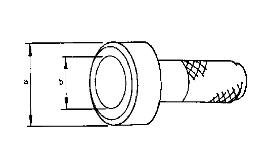
Drift

Installing front oil seal

a: 77 mm (3.03 in) dia.

b: 55 mm (2.185 in) dia.

KV40105740

( — )

Drift

Installing side oil seal (cover side)

a: 57 mm (2.24 in) dia.

b: 48 mm (1.89 in) dia.

KV31103000

(NI-38982)

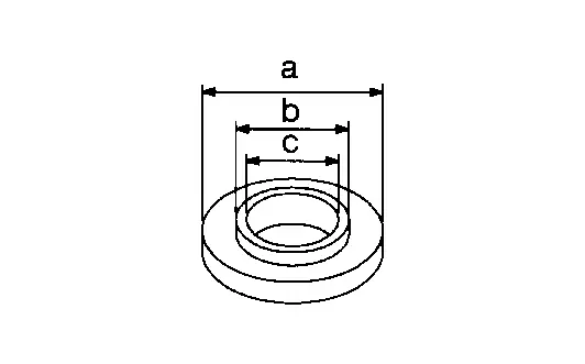
Drift

Installing side oil seal (carrier side)

a: 70 mm (2.76 in) dia.

b: 59 mm (2.32 in) dia.

c: 49 mm (1.93 in) dia.

ST35325000

( — )

Drift bar
Installing side oil seal (carrier side)

—

(NI-53123)

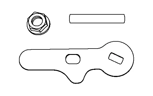
Park lock tool
Placing transaxle in neutral

Commercial Service Tools

Tool nameDescription
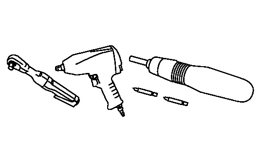
Power tool
Loosening nuts, screws and bolts

Lubricant or/and Sealant

ItemUse
Electro-hydraulic coupling oil (Genuine NISSAN part) Filling when the parts of electro-hydraulic coupling assembly and/or rear final drive assembly is disassembled
Red lead or equivalent Checking tooth contact

Always Replace with New Parts

Never Reuse These PartsPart # PrefixFor additional information:
Hose clamp 38322BA REAR FINAL DRIVE ASSEMBLY EXPLODED VIEW
Breather tube 38322A REAR FINAL DRIVE ASSEMBLY EXPLODED VIEW
O-ring 38250E REAR FINAL DRIVE ASSEMBLY EXPLODED VIEW
Nut 55011BC REAR FINAL DRIVE ASSEMBLY EXPLODED VIEW
Breather 38322 REAR FINAL DRIVE ASSEMBLY EXPLODED VIEW
Companion flange lock nut 38351D ELECTRO-HYDRAULIC COUPLING EXPLODED VIEW
Companion flange 38761 ELECTRO-HYDRAULIC COUPLING EXPLODED VIEW
Electro-hydraulic coupling oil seal 38765F ELECTRO-HYDRAULIC COUPLING EXPLODED VIEW
O-ring 38334 ELECTRO-HYDRAULIC COUPLING EXPLODED VIEW
Plug 38351F ELECTRO-HYDRAULIC COUPLING EXPLODED VIEW
Side oil seal 38342 ELECTRO-HYDRAULIC COUPLING EXPLODED VIEW
Stud 38351C ELECTRO-HYDRAULIC COUPLING EXPLODED VIEW
Filler plug 38351F ELECTRO-HYDRAULIC COUPLING EXPLODED VIEW
Bolt 38300A ELECTRO-HYDRAULIC COUPLING EXPLODED VIEW

System Description. Structure and Operation Nissan Pathfinder 2022

Sectional View
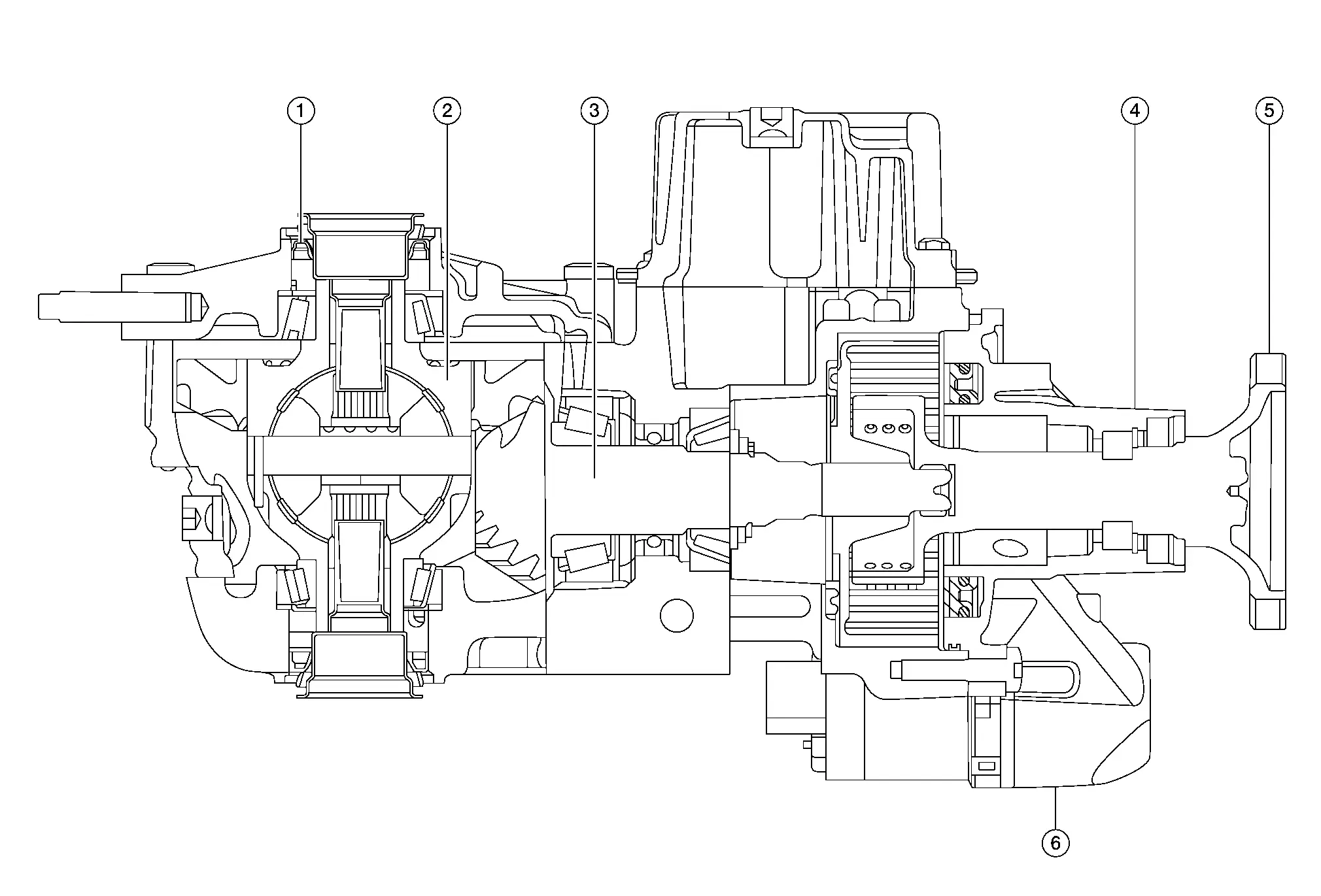
1. Side oil seal 2. Differential case 3. Drive pinion
4. Electro-hydraulic coupling 5. Companion flange 6. Actuator assembly

Electro-Hydraulic Coupling

The electro-hydraulic coupling operates as the 4WD system. For the operation, refer to Operation Description.

Symptom Diagnosis. Noise, Vibration and Harshness (nvh) Troubleshooting Nissan Pathfinder 2026

NVH Troubleshooting Chart

Use the chart below to find the cause of the symptom. If necessary, repair or replace these parts.

Possible cause and SUSPECTED PARTSSymptomReference
NoiseVibration
Gear tooth rough X — Refer to Inspection
Gear contact improper X — —
Tooth surfaces worn X — Refer to Inspection
Backlash incorrect X — —
Companion flange excessive runout X — —
Gear oil improper X — Refer to Inspection
PROPELLER SHAFT X — Refer to NVH Troubleshooting Chart
AXLE AND SUSPENSION X —

Refer to NVH Troubleshooting Chart

Refer to NVH Troubleshooting Chart

Refer to NVH Troubleshooting Chart

Refer to NVH Troubleshooting Chart
TIRE X — Refer to NVH Troubleshooting Chart
ROAD WHEEL X — Refer to NVH Troubleshooting Chart
DRIVE SHAFT X —

Refer to NVH Troubleshooting Chart

Refer to NVH Troubleshooting Chart
BRAKE X — Refer to NVH Troubleshooting Chart
STEERING X — Refer to NVH Troubleshooting Chart
Electro-hydraulic coupling X X Refer to Removal and Installation

×: Applicable

Periodic Maintenance. Rear Differential Gear Oil Nissan Pathfinder 2022

Inspection

REAR DIFFERENTIAL GEAR OIL LEAKS

Check that rear differential gear oil is not leaking from the final drive assembly or around it.

REAR DIFFERENTIAL GEAR OIL LEVEL

Remove and discard filler plug (1).
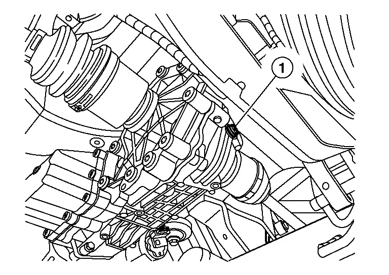
: Front

Rear differential gear oil level should be level with the bottom of the filler plug hole. Add rear differential gear oil if necessary. Refer to Fluids and Lubricants (United States and Canada) or Fluids and Lubricants (Mexico).

Install filler plug (1) and tighten to the specified torque. Refer to Exploded View.

Draining

Remove and discard drain plug (1), and drain rear differential gear oil.
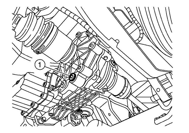
: Front

Install drain plug (1) and tighten to the specified torque. Refer to Exploded View.

Refilling

Remove and discard filler plug (1).
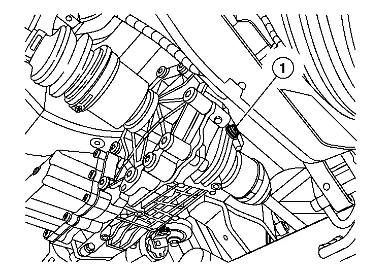
: Front

Fill with new rear differential gear oil to the specified level near the filler plug hole.

Rear differential gear oil grade and viscosity : Refer to Fluids and Lubricants (United States and Canada) or Fluids and Lubricants (Mexico).
Rear differential gear oil capacity : Refer to General Specification.

Install filler plug (1) and tighten to specified torque. Refer to Exploded View.

Unit Removal and Installation. Rear Final Drive Assembly Nissan Pathfinder 5th Gen

Exploded View
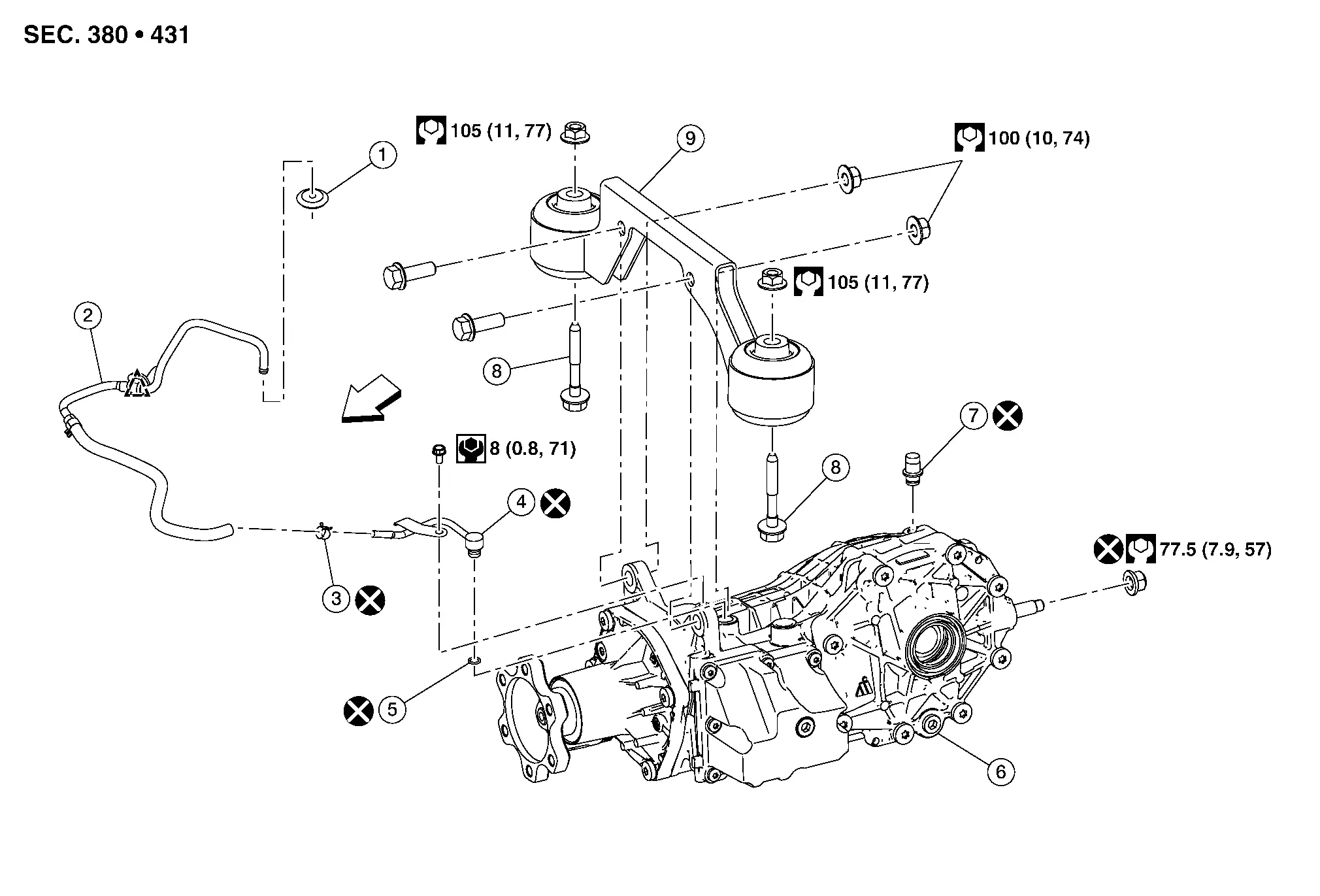
1. Plug 2. Breather hose 3. Hose clamp
4. Breather tube 5. O-ring 6. Final drive assembly
7. Breather 8. Bolt 9. Final drive assembly bracket
Clip Front

Removal and Installation

REMOVAL

Drain rear differential gear oil. Refer to Draining.

Remove rear wheel hub (LH/RH). Refer to Removal and Installation.

Remove the rear propeller shaft from the final drive assembly and support the rear propeller shaft with suitable wire. Refer to Removal and Installation.

Remove the Nissan Pathfinder vehicle spare tire.

Remove rear stabilizer bar. Refer to Removal and Installation.

Remove 4WD harness bracket.

Disconnect the harness connector from 4WD control unit.

Remove breather hose from breather tube.

Support rear final drive assembly with a suitable jack.

Remove final drive bracket bolts.

Remove rear final drive nut ( ) at rear suspension member, and remove rear final drive from Nissan Pathfinder vehicle.
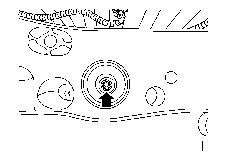
INSTALLATION

Installation is in the reverse order of removal.

  • When oil leaks while removing rear final drive assembly, check oil level after the installation. Refer to Inspection.

  • If replacing rear final drive assembly, perform "ADDITIONAL SERVICE WHEN REPLACING REAR FINAL DRIVE ASSEMBLY". Refer to Description.

Service Data and Specifications (SDS) Nissan Pathfinder R53

General Specification

Applied model4WD
VQ35DD
9AT
Final drive modelR145
Gear ratio 2.466
Number of teeth (Drive gear/Drive pinion) 37/15
Oil type Refer to Fluids and Lubricants (United States and Canada) or Fluids and Lubricants (Mexico).
Final drive oil capacity (Approx.) (US pt, lmp pt) 0.45 (1, 3/4)
Electro-hydraulic coupling oil capacity (Approx.) (US pt, lmp pt) 0.69 (1–1/2, 1–1/4)
Number of pinion gears 2