Brake Control System - System Description

In this manual: Brake Control System - System Description
General Information — 8Engine :: Engine Mechanical — 19Engine Lubrication System - Precautions. Preparation — 1Engine Lubrication System - Lubrication System (System Description). Engine Oil Pressure (Basic Inspection). Service Data and Specifications (SDS) — 1Engine Cooling System - Precautions. Preparation. Service Data and Specifications (SDS) — 1Engine Cooling System - Engine Coolant — 1Engine Control System - System Description — 1System Description - Component Parts ++ — 1System Description - System ++ — 1Engine Control System - Ecu Diagnosis Information — 1Ecu Diagnosis Information - Ecm ++ — 1Engine Control System - Basic Inspection — 1Basic Inspection - Diagnosis and Repair Workflow ++ — 1Basic Inspection - Basic Inspection ++ — 1Basic Inspection - Additional Service When Replacing Ecm ++ — 1Basic Inspection - Fuel Pressure Check ++ — 1Basic Inspection - How to Set Srt Code ++ — 1Basic Inspection - How to Erase Permanent Dtc ++ — 1Engine Control System - Dtc/circuit Diagnosis — 1Engine Control System - Symptom Diagnosis — 1Engine Control System - Periodic Maintenance — 1Engine Control System - Removal and Installation — 1Fuel System - Precautions. Preparation. Service Data and Specifications (SDS) — 1Fuel System - Fuel System (Periodic Maintenance). Fuel Level Sensor Unit (Disassembly and Assembly) — 1Exhaust System - Precautions. Preparation — 1Exhaust System - Exhaust System (Periodic Maintenance). Exhaust System (Removal and Installation) — 1Starting System - Precautions. Preparation. Starter Motor (Service Data and Specifications (sds)) — 1Starting System - Diagnosis and Repair Work Flow — 1Starting System - Starting System (Symptom Diagnosis). Starter Motor (Removal and Installation) — 1Accelerator Control System - Precautions. Service Data and Specifications (SDS) — 1Accelerator Control System - Accelerator Pedal Assembly — 1Transmission & Driveline :: Transaxle & Transmission — 21Driveline - System Description — 1Transfer: Ty92b - Ecu Diagnosis Information. Awd Control Unit ++ — 1Driveline - Basic Inspection — 1Driveline - Dtc/circuit Diagnosis — 1Driveline - Symptom Diagnosis — 1Driveline - Removal and Installation — 1Transfer: Ty92b - Unit Removal and Installation. Transfer Assembly ++ — 1Driveline - Unit Disassembly and Assembly — 1Driveline - Basic Inspection — 1Driveline - Removal and Installation — 1Driveline - Unit Disassembly and Assembly — 1Front Axle - Precautions. Preparation — 1Front Axle - Noise, Vibration and Harshness (nvh) Troubleshooting (Symptom Diagnosis). Service Data and Specifications (SDS) — 1Front Axle - Front Drive Shaft Boot — 1Front Axle - Front Drive Shaft — 1Rear Axle - Precautions. Preparation. Service Data and Specifications (SDS) — 1Rear Axle - Noise, Vibration and Harshness (nvh) Troubleshooting — 1Rear Axle - Rear Drive Shaft — 1Suspension :: Front Suspension — 7Rear Suspension - Precautions. Preparation — 1Rear Suspension - Noise, Vibration and Harshness (nvh) Troubleshooting (Symptom Diagnosis). Service Data and Specifications (SDS) — 1Rear Suspension - Rear Suspension Assembly — 1Road Wheels & Tires - Precautions — 1Road Wheels & Tires - Preparation. Bcm (Ecu Diagnosis Information). Service Data and Specifications (SDS) — 1Road Wheels & Tires - System — 1Brakes :: Brake System — 9Parking Brake System - Precautions. Preparation — 1Parking Brake System - System — 1Vdc/tcs/abs - Precautions ++ — 1Brake Control System - System Description — 1System Description - Component Parts ++ — 1System Description - System ++ — 1Brake Control System - Basic Inspection — 1Brake Control System - Symptom Diagnosis — 1Brake Control System - Removal and Installation — 1Brake Control System - System Description — 1Brake Control System - Dtc/circuit Diagnosis — 1Brake Control System - Removal and Installation — 1Brake Control System - System Description — 1Brake Control System - Basic Inspection — 1Brake Control System - Symptom Diagnosis — 1Brake Control System - System Description — 1Brake Control System - Basic Inspection — 1Brake Control System - Symptom Diagnosis — 1Steering :: Steering System — 9Steering Control System - Precautions — 1Steering Control System - System — 1Steering Control System - Eps Control Unit (Ecu Diagnosis Information. Removal and Installation) — 1Restraints :: Seat Belt — 7Srs Air Bag - Precautions. Preparation — 1Srs Air Bag - Collision Diagnosis — 1Srs Air Bag - Occupant Classification System — 1Srs Air Bag Control System - Precautions — 1Srs Air Bag Control System - System — 1Srs Air Bag Control System - Diagnosis Sensor Unit — 1Srs Air Bag Control System - Inspection and Adjustment — 1Ventilation, Heater & Air Conditioner :: Ventilation System — 6Heater & Air Conditioning System - Precautions — 1Heater & Air Conditioning System - Preparation — 1Heater & Air Conditioning System - Component Parts — 1Heater & Air Conditioning System - Diagnosis and Repair Work Flow — 1Heater & Air Conditioning System - Compressor — 1Heater & Air Conditioning System - Cooler Pipe and Hose — 1Heater & Air Conditioning System - Condenser. Condenser — 1Heater & Air Conditioning System - Heating and Cooling Unit Assembly — 1Heater & Air Conditioning System - Service Data and Specifications (SDS) — 1Heater & Air Conditioning Control System - System Description — 1System Description - Component Parts ++ — 1System Description - System ++ — 1System Description - Operation ++ — 1Heater & Air Conditioning Control System - Ecu Diagnosis Information — 1Heater & Air Conditioning Control System - Basic Inspection — 1Heater & Air Conditioning Control System - Dtc/circuit Diagnosis — 1Heater & Air Conditioning Control System - Symptom Diagnosis — 1Heater & Air Conditioning Control System - Removal and Installation — 1Body Interior :: Interior — 8Instrument Panel - Precautions. Preparation. Clip List — 1Instrument Panel - Squeak and Rattle Trouble Diagnoses — 1Instrument Panel - Cluster Lid C — 1Seat - Precautions — 1Seat - Preparation. Clip List — 1Seat - Component Parts — 1Seat - System — 1Seat - Diagnosis and Repair Work Flow — 1Seat - Front Seat — 1Seat - Second Row Seats — 1Seat - Third Row Seats — 1Seat - Front Seat — 1Seat - Second Row Seat — 1Seat - Third Row Seat — 1Automatic Drive Positioner - Precautions. Preparation — 1Automatic Drive Positioner - System — 1Automatic Drive Positioner - Diagnosis and Repair Work Flow — 1Automatic Drive Positioner - Inspection and Adjustment — 1Body Exterior, Doors, Roof & Vehicle Security :: Door & Lock — 38Security Control System - Precautions — 1Security Control System - System — 1Security Control System - Ecm, Bcm, Intelligent Key Unit, Ipdm E/r — 1Security Control System - Vehicle Security System Cannot Be Set — 1Glass & Window System - Precautions. Preparation — 1Glass & Window System - Squeak and Rattle Trouble Diagnoses — 1Power Window Control System - Precautions. Preparation — 1Power Window Control System - Power Supply and Ground Circuit — 1Power Window Control System - Power Window Motor Circuit — 1Power Window Control System - Front Power Window Rh Alone Does Not Operate — 1Power Window Control System - Rear Lh Side Power Window Alone Does Not Operate — 1Power Window Control System - Rear Rh Side Power Window Alone Does Not Operate — 1Roof - Precautions. Preparation — 1Roof - Power Supply and Ground Circuit — 1Roof - Moonroof Switch Assembly — 1Roof - Lin Communication Circuit — 1Roof - Auto Operation Does Not Operate — 1Roof - Anti-Pinch Function Does Not Operate — 1Exterior - Precautions. Preparation. Clip List (Preparation) — 1Exterior - Squeak and Rattle Trouble Diagnoses — 1Exterior - Fender Protector — 1Exterior - Over Fender — 1Exterior - Under Cover — 1Exterior - Roof Side Rail — 1Body Repair - Service Information — 1Service Information - Sheet Metal Work ++ — 1Service Information - Body Welding and Precautions ++ — 1Service Information - Safety and Health ++ — 1Service Information - Repairing Procedures and Precautions ++ — 1Body Repair - Precaution — 1Body Repair - Preparation — 1Body Repair - Removal and Installation — 1Driver Controls :: Mirrors — 8Exterior Lighting System - System Description — 1System Description - Component Parts ++ — 1Exterior Lighting System - Basic Inspection — 1Exterior Lighting System - Dtc/circuit Diagnosis — 1Exterior Lighting System - Symptom Diagnosis — 1Exterior Lighting System - Periodic Maintenance — 1Exterior Lighting System - Removal and Installation — 1Interior Lighting System - Precautions. Preparation — 1Interior Lighting System - Component Parts. Interior Lighting System — 1Interior Lighting System - System — 1Interior Lighting System - Diagnosis and Repair Work Flow — 1Interior Lighting System - Interior Lighting System Symptoms (Symptom Diagnosis). Bcm (Ecu Diagnosis Information). Service Data and Specifications (SDS) — 1Interior Lighting System - Foot Lamp — 1Wiper & Washer - Precautions — 1Wiper & Washer - Preparation. Bcm, Ipdm E/r (Ecu Diagnosis Information). Service Data and Specifications (SDS) — 1Wiper & Washer - System — 1Wiper & Washer - Diagnosis and Repair Work Flow — 1Defogger - Precautions. Bcm, A/c Auto Amp. (Ecu Diagnosis Information) — 1Defogger - Diagnosis and Repair Work Flow — 1Horn - Precautions — 1Electrical & Power Control :: Power Outlet — 13Body Control System - Precautions. Preparation — 1Body Control System - Component Parts — 1Body Control System - System — 1Body Control System - Diagnosis System (bcm) — 1Body Control System - Bcm — 1Lan System - System Description — 1Lan System - System Description — 1Lan System - Dtc/circuit Diagnosis — 1Lan System - System Description — 1Lan System - Dtc/circuit Diagnosis — 1Power Control System - System Description — 1Power Control System - Basic Inspection — 1Power Control System - Dtc/circuit Diagnosis — 1Power Control System - System Description — 1Power Control System - Basic Inspection — 1Power Control System - Dtc/circuit Diagnosis — 1Power Control System - Removal and Installation — 1Charging System - Precautions. Preparation. Ecm, Ipdm E/r (Ecu Diagnosis Information) — 1Charging System - Diagnosis and Repair Work Flow — 1Charging System - Charging System (Symptom Diagnosis). Generator (Removal and Installation). Service Data and Specifications (SDS) — 1Power Supply, Ground & Circuit Elements - Precautions. Preparation. Service Data and Specifications (SDS) — 1Driver Information & Multimedia :: Meter, Warning Lamp & Indicator — 25Warning Chime System - Application Notice (How to Use This Manual). Precautions — 1Warning Chime System - System — 1Warning Chime System - Diagnosis System (combination Meter) — 1Warning Chime System - Bcm, Combination Meter (Ecu Diagnosis Information). Diagnosis and Repair Work Flow (Basic Inspection) — 1Sonar System - Precautions. Preparation — 1Sonar System - Sonar Control Unit — 1Dtc/circuit Diagnosis - B2720 Corner Sensor [rl] ++ — 1Audio, Visual & Navigation System - System Description — 1System Description - Component Parts ++ — 1System Description - System ++ — 1Audio, Visual & Navigation System - Ecu Diagnosis Information — 1Audio, Visual & Navigation System - Basic Inspection — 1Audio, Visual & Navigation System - Dtc/circuit Diagnosis — 1Dtc/circuit Diagnosis - Multi Av (av Control Unit) ++ — 1Audio, Visual & Navigation System - Symptom Diagnosis — 1Symptom Diagnosis - Multi Av System ++ — 1Audio, Visual & Navigation System - Removal and Installation — 1Audio, Visual & Navigation System - System Description — 1Audio, Visual & Navigation System - Ecu Diagnosis Information — 1Audio, Visual & Navigation System - Basic Inspection — 1Audio, Visual & Navigation System - Dtc/circuit Diagnosis — 1Audio, Visual & Navigation System - Symptom Diagnosis — 1Audio, Visual & Navigation System - Removal and Installation — 1Audio, Visual & Navigation System - System Description — 1Audio, Visual & Navigation System - Basic Inspection — 1Audio, Visual & Navigation System - Dtc/circuit Diagnosis — 1Audio, Visual & Navigation System - Symptom Diagnosis — 1Audio, Visual & Navigation System - Removal and Installation — 1Audio, Visual & Navigation System - System Description — 1Audio, Visual & Navigation System - Basic Inspection — 1Audio, Visual & Navigation System - Dtc/circuit Diagnosis — 1Audio, Visual & Navigation System - Symptom Diagnosis — 1Audio, Visual & Navigation System - Removal and Installation — 1Cruise Control & Driver Assistance :: Cruise Control System — 17Driver Assistance System - System Description — 1Driver Assistance System - Basic Inspection — 1Driver Assistance System - Dtc/circuit Diagnosis — 1Driver Assistance System - System Description — 1System Description - Component Parts ++ — 1System Description - System ++ — 1System Description - Operation ++ — 1System Description - Handling Precaution ++ — 1Driver Assistance System - Ecu Diagnosis Information — 1Driver Assistance System - Basic Inspection — 1Basic Inspection - Distance Sensor Alignment ++ — 1Basic Inspection - Camera Aiming Adjustment ++ — 1Basic Inspection - Action Test ++ — 1Driver Assistance System - Dtc/circuit Diagnosis — 1Dtc/circuit Diagnosis - Laser/radar (distance Sensor) ++ — 1Dtc/circuit Diagnosis - Lane Camera (front Camera Unit) ++ — 1Driver Assistance System - Symptom Diagnosis — 1Driver Assistance System - Removal and Installation — 1Driver Assistance System - System Description — 1System Description - System ++ — 1Driver Assistance System - Basic Inspection — 1Driver Assistance System - Dtc/circuit Diagnosis — 1Drive Mode System - Precautions — 1Drive Mode System - Component Parts. Drive Mode System — 1Drive Mode System - System — 1Drive Mode System - Diagnosis and Repair Work Flow — 1Drive Mode System - Drive Mode Select Switch Circuit — 1Maintenance - Precautions. Preparation — 1Maintenance - General Maintenance — 1Maintenance - Periodic Maintenance — 1Maintenance - Recommended Fluids and Lubricants — 1Maintenance - Engine Maintenance — 1Maintenance - Chassis and Body Maintenance — 1Engine Lubrication System - Periodic Maintenance — 1Engine Lubrication System - Removal and Installation — 1Engine Cooling System - System Description — 1Engine Cooling System - Removal and Installation — 1Engine Control System - Vq35dd — 1Fuel System - Removal and Installation — 1Starting System - System Description — 1Starting System - Dtc/circuit Diagnosis — 1Driveline - Transfer: Ty92b — 1Driveline - Rear Propeller Shaft: 3fcj-Cvj — 1Driveline - Rear Final Drive: R145 — 1Front Axle - Periodic Maintenance — 1Front Axle - Removal and Installation — 1Rear Axle - Periodic Maintenance — 1Rear Axle - Removal and Installation — 1Rear Suspension - Removal and Installation — 1Road Wheels & Tires - System Description — 1Road Wheels & Tires - Basic Inspection — 1Road Wheels & Tires - Dtc/circuit Diagnosis — 1Road Wheels & Tires - Symptom Diagnosis — 1Road Wheels & Tires - Periodic Maintenance — 1Road Wheels & Tires - Removal and Installation — 1Parking Brake System - System Description — 1Parking Brake System - Basic Inspection — 1Parking Brake System - Dtc/circuit Diagnosis — 1Parking Brake System - Symptom Diagnosis — 1Parking Brake System - Removal and Installation — 1Brake Control System - Vdc/tcs/abs — 1Brake Control System - Automatic Brake Hold — 1Brake Control System - Automatic Emergency Braking — 1Brake Control System - Rear Automatic Braking — 1Steering Control System - System Description — 1Steering Control System - Basic Inspection — 1Steering Control System - Dtc/circuit Diagnosis — 1Steering Control System - Symptom Diagnosis — 1Srs Air Bag - Removal and Installation — 1Srs Air Bag Control System - System Description — 1Srs Air Bag Control System - Basic Inspection — 1Srs Air Bag Control System - Symptom Diagnosis — 1Heater & Air Conditioning System - Symptom Diagnosis — 1Heater & Air Conditioning System - Periodic Maintenance — 1Heater & Air Conditioning Control System - Automatic Air Conditioning — 1Instrument Panel - Removal and Installation — 1Instrument Panel - Unit Disassembly and Assembly — 1Seat - Ecu Diagnosis Information — 1Seat - Dtc/circuit Diagnosis — 1Seat - Symptom Diagnosis — 1Automatic Drive Positioner - System Description — 1Automatic Drive Positioner - Ecu Diagnosis Information — 1Automatic Drive Positioner - Dtc/circuit Diagnosis — 1Automatic Drive Positioner - Symptom Diagnosis — 1Automatic Drive Positioner - Removal and Installation — 1Security Control System - System Description — 1Security Control System - Basic Inspection — 1Security Control System - Dtc/circuit Diagnosis — 1Security Control System - Symptom Diagnosis — 1Security Control System - Removal and Installation — 1Glass & Window System - Removal and Installation — 1Power Window Control System - System Description — 1Power Window Control System - Ecu Diagnosis Information — 1Power Window Control System - Basic Inspection — 1Power Window Control System - Dtc/circuit Diagnosis — 1Power Window Control System - Symptom Diagnosis — 1Power Window Control System - Removal and Installation — 1Roof - System Description — 1Roof - Ecu Diagnosis Information — 1Roof - Basic Inspection — 1Roof - Dtc/circuit Diagnosis — 1Roof - Symptom Diagnosis — 1Roof - Removal and Installation — 1Exterior - System Description — 1Exterior - Removal and Installation — 1Body Repair - Repair Information — 1Exterior Lighting System - Led Headlamp — 1Interior Lighting System - Dtc/circuit Diagnosis — 1Interior Lighting System - Removal and Installation — 1Wiper & Washer - System Description — 1Wiper & Washer - Dtc/circuit Diagnosis — 1Wiper & Washer - Symptom Diagnosis — 1Wiper & Washer - Removal and Installation — 1Defogger - System Description — 1Defogger - Dtc/circuit Diagnosis — 1Defogger - Symptom Diagnosis — 1Defogger - Removal and Installation — 1Horn - Removal and Installation — 1Body Control System - Basic Inspection — 1Body Control System - Dtc/circuit Diagnosis — 1Body Control System - Symptom Diagnosis — 1Body Control System - Removal and Installation — 1Lan System - Can Fundamental — 1Lan System - Can — 1Lan System - Can Gateway — 1Power Control System - Ipdm E/r — 1Power Control System - Power Distribution System — 1Charging System - System Description — 1Charging System - Dtc/circuit Diagnosis — 1Power Supply, Ground & Circuit Elements - System Description — 1Power Supply, Ground & Circuit Elements - Basic Inspection — 1Power Supply, Ground & Circuit Elements - Removal and Installation — 1Warning Chime System - System Description — 1Warning Chime System - Dtc/circuit Diagnosis — 1Warning Chime System - Symptom Diagnosis — 1Sonar System - System Description — 1Sonar System - Basic Inspection — 1Sonar System - Dtc/circuit Diagnosis — 1Sonar System - Symptom Diagnosis — 1Sonar System - Removal and Installation — 1Audio, Visual & Navigation System - Nissanconnect — 1Audio, Visual & Navigation System - Intelligent Around View Monitor System — 1Audio, Visual & Navigation System - Rear View Monitor System — 1Audio, Visual & Navigation System - Telematics System — 1Driver Assistance System - Adas Control Unit 2 — 1Driver Assistance System - Driver Assistance System — 1Driver Assistance System - Chassis Control — 1Drive Mode System - Removal and Installation — 1Dtc/circuit Diagnosis (C053c Wheel Speed Sensor ... U2141 Can Comm Circuit) — 1Dtc/circuit Diagnosis (P0011 Intake Valve Timing Control ... P0111 Iat Sensor) — 1Dtc/circuit Diagnosis (P0116 Engine Coolant Temperature Sensor ... P025b Fuel Pump Module a) — 1Dtc/circuit Diagnosis (P026b Injection Timing ... P0420 Three Way Catalyst Function) — 1Dtc/circuit Diagnosis (P0441 Evap Control System ... P0524 Engine Oil Pressure) — 1Dtc/circuit Diagnosis (P0532 A/c Refrigerant Pressure Sensor ... P064d Ecm) — 1Dtc/circuit Diagnosis (P06da Engine Oil Pressure Control Solenoid Valve ... P1217 Engine Over Temperature) — 1Dtc/circuit Diagnosis (P1220 Fuel Pump Control Module (fpcm) ... P1574 Ascd Vehicle Speed Sensor) — 1Dtc/circuit Diagnosis (P1575 Brake Switch ... P2101 Electric Throttle Control Function) — 1Dtc/circuit Diagnosis (P2118 Throttle Control Motor ... P34ac Electric Intake Valve Timing Control Actuator) — 1Dtc/circuit Diagnosis (Active Grille Shutter ... High Pressure Fuel Pump) — 1Dtc/circuit Diagnosis (Ignition Signal ... Variable Induction Air System) — 14012 C1040 Emergency Brake — 14013 C106a Wheel Sensor — 14014 C1078-55 Not Configuration — 14015 C10b4-98 Overheat — 14016 B1001 Lap Pre-Tensioner Lh — 14017 B0001 Driver Air Bag Module — 14018 B100e Knee Air Bag Module Rh — 14019 B142x Collision Detection — 1Dtc/circuit Diagnosis (B20c7-11 A/c Clutch ... B24a6-11 in-Vehicle Sensor) — 1Dtc/circuit Diagnosis (B24a6-15 in-Vehicle Sensor ... U2140-87 Can Comm Err (ecm)) — 1Dtc/circuit Diagnosis (C1f00-1c Control Unit ... C1f04-61 Brake Sw/stop Lamp Sw) — 1Dtc/circuit Diagnosis (C1f05-49 Front Camera Unit ... C1f70-87 Ethernet Circuit) — 1
4steps
~24min
2/5difficulty
Done 0 of 4
  • Component Parts
  • System
  • Operation
  • Handling Precaution
  • Diagnosis System (adas Control Unit 2)

Component Parts Nissan Pathfinder SUV

Rear Automatic Braking System

Component Parts Location
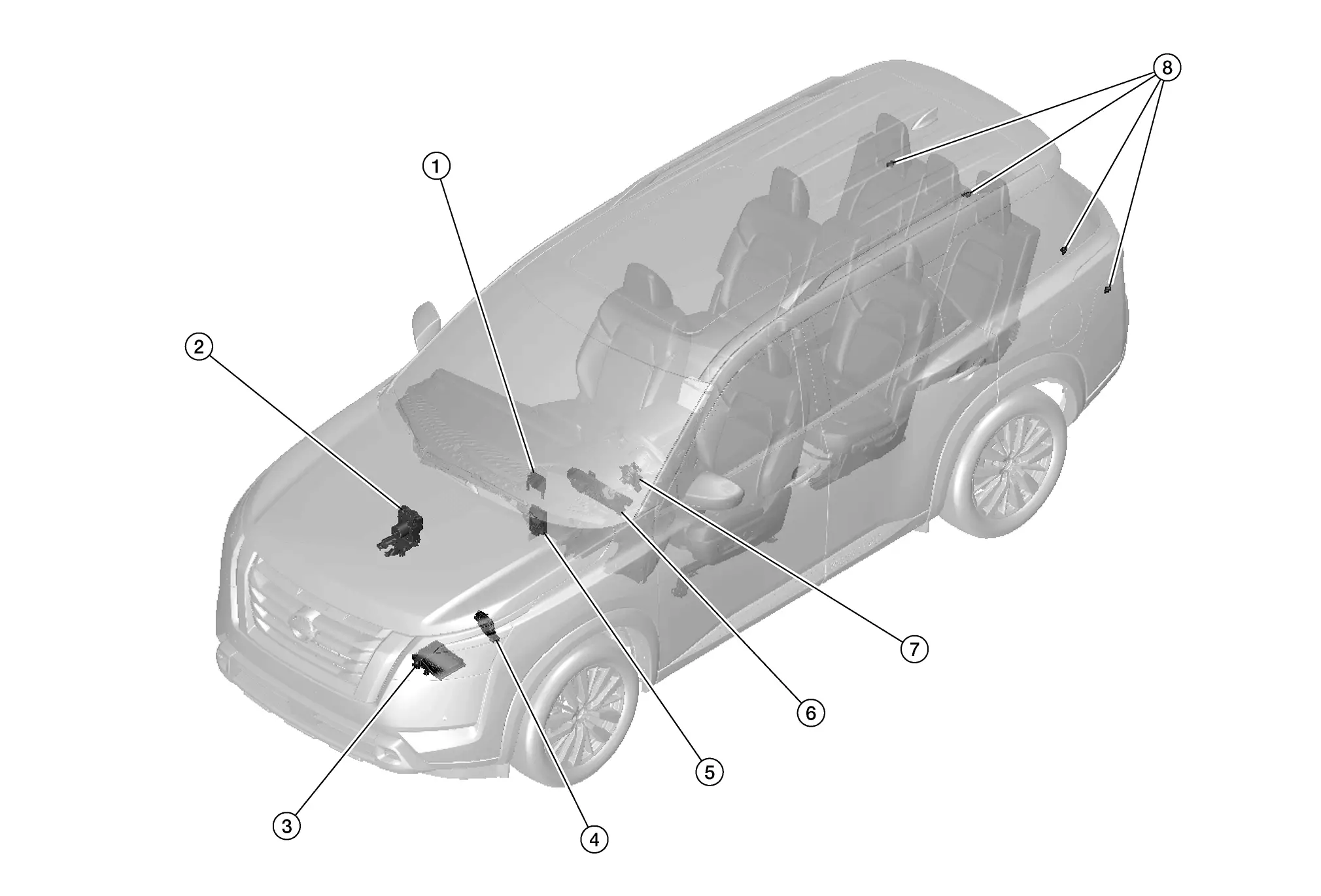
No.Component partsFunction
1. Sonar control unit

Sonar sensors signals are received by the sonar control unit and transmitted to the combination meter via CAN communication for RAB operation.

Refer to Component Parts Location for detailed component location.
2. ABS (Anti-lock braking system) actuator and electric unit (control unit) Refer to ABS Actuator and Electric Unit (Control Unit).
3. TCM (Transmission Control Module) AT control related signal is transmitted to sonar control unit via CAN communication.
4. ECM (Engine Control Module) When Rear Automatic Braking operates, an engine torque down request signal is received from the sonar control unit.
5. ADAS (Advanced Driver Assistance System) control unit 2
  • Control each system, based on CAN communication and ITS communication signals received from each control unit

  • Transmits signals necessary for control between CAN communication and ITS communication

Refer to Component Parts Location for detailed component location.
6. Combination meter

Performs the following operations using the signals received from the sonar control unit via CAN comunication:

  • Displays the operation status

  • System display and warning

Refer to Component Part Location (7 Inch Information Display) for detailed component location.
7. Steering angle sensor

Transmits the steering angle sensor malfunction signal to ADAS control unit 2, and ABS actuator and electric unit (control unit) via CAN communication

Refer to Steering Angle Sensor.
8. Rear sonar sensors Refer to Rear sonar Sensors.

System Nissan Pathfinder R53

System Description

SYSTEM DIAGRAM

ComponentFunction
ECM ECM (With Barometric Pressure Sensor)
TCM TCM
ABS actuator and electric unit (control unit) ABS Actuator and Electric Unit (Control Unit)
Chassis control module Chassis Control Module
BCM System Description
Steering angle sensor Steering Angle Sensor
Combination meter (FULL TFT METER) Combination Meter
Combination meter (7 INCH INFORMATION DISPLAY) Combination Meter
Sonar control unit System Description
Around view monitor control unit Around View Monitor Control Unit
ADAS control unit 2 ADAS Control Unit 2

ADAS CONTROL UNIT 2 INPUT/OUTPUT SIGNAL ITEM

Input Signal Item

Transmit unitSignal nameDescription
ECM CAN communication Closed throttle position signal Receives idle position state (ON/OFF)
Accelerator pedal position signal Receives accelerator pedal position (angle)
Engine speed signal Receives engine speed
TCM CAN communication Input speed signal Receives the number of revolutions of input shaft
Current gear position signal Receives a current gear position
Shift position signal Receives a selector lever position
Output shaft revolution signal Receives the number of revolutions of output shaft
ABS actuator and electric unit (control unit) CAN communication ABS malfunction signal Receives a malfunction state of ABS
TCS malfunction signal Receives a malfunction state of TCS
VDC malfunction signal Receives a malfunction state of VDC
Nissan Pathfinder Vehicle speed signal (ABS) Receives wheel speeds of four wheels
Brake fluid pressure signal Receives brake fluid pressure
BCM CAN communication Stop lamp switch signal Receives an operational state of the brake pedal
Steering angle sensor CAN communication Steering angle sensor signal Receives the number of revolutions, turning direction of the steering wheel
Combination meter CAN communication System selection signal Receives a selection state of each item selected with the combination meter
Sonar control unit CAN communication Sonar sensor signal Receives obstacle information (existence & distance)

Output Signal Item

Reception unitSignal nameDescription
ECM CAN communication Wheel torque request signal Transmits a signal to control the engine torque
Combination meter CAN communication Meter display signal Transmits a signal to display a state of the system on the information display
Buzzer output signal Transmits a signal to activate buzzer
RAB warning lamp signal
  • Transmits a signal to illuminate RAB warning lamp

  • Transmits an ON/OFF state of the RAB

BCM CAN communication Stop lamp request signal Transmits a signal to activates the stop lamp
ABS actuator and electric unit (control unit) (via chassis control module) CAN communication Brake fluid pressure control signal Transmits a brake fluid pressure control signal to activates the brake
Around view monitor control unit CAN communication RAB warning signal Transmits a RAB warning signal to appear the red frame in the center display

FUNCTION DESCRIPTION

  • The Rear Automatic Braking system can assist the driver when the vehicle is backing up and approaching objects directly behind the Nissan Pathfinder vehicle.

  • When the shift lever is in the R (Reverse) position and the Nissan Pathfinder vehicle speed is less than approximately 15 km/h, the RAB system operates.

  • The RAB system detects obstacles behind the Nissan Pathfinder vehicle using the sonar sensors.

  • If a risk of a collision with an obstacle is detected when own Nissan Pathfinder vehicle is backing up, the RAB system warning indicator blinks in the vehicle information display, a red frame appears in the center display (with Intelligent Around View Monitor system), and the system chimes three times.

  • The system automatically applies the brakes.

OPERATION DESCRIPTION

  • Sonar detects a object approaching, and transmits the object detection signal to ADAS control unit 2 via CAN communication.

  • The ADAS control unit 2 performs the following operations according to the degree of possibility of a collision.

    • Transmits the buzzer output signal to the combination meter and sounds the buzzer.

    • Transmits the meter display signal to the combination meter and displays the RAB system warning indicator.

    • Transmits the brake fluid pressure control signal to the ABS actuator and electric unit (control unit) and performs the brake control.

    • Transmits the stop lamp request signal to BCM and turn ON the stop lamp.

OPERATION CONDITION

ADAS control unit 2 performs the control when the following conditions are satisfied.

  • RAB system: ON

  • Vehicle speed: Less than approximately 15 km/h

  • When there is a possibility of a collision with the object backward.

CANCEL CONDITION

The ADAS control unit 2 cancels the operation when the system is under any conditions of the operation cancellation condition.

  • When the system judges that the vehicle comes to a standstill by the system control.

  • When the system malfunction occurs.

  • When the sonar area of the rear bumper is dirty and the measurement of the distance between the object becomes difficult.

Fail-safe (ADAS Control Unit 2)

Refer to Fail-safe (ADAS Control Unit 2).

Warning Lamp/Indicator Lamp

NameDesignFunction
RAB warning lamp
  • The RAB warning lamp warns the driver that RAB system is OFF.

  • The RAB warning lamp warns the driver of a malfunction in the RAB system.

  • For layout, Refer to Design(FULL TFT METER) or Design(7 inch Information Display)

Operation Nissan Pathfinder SUV

Operation

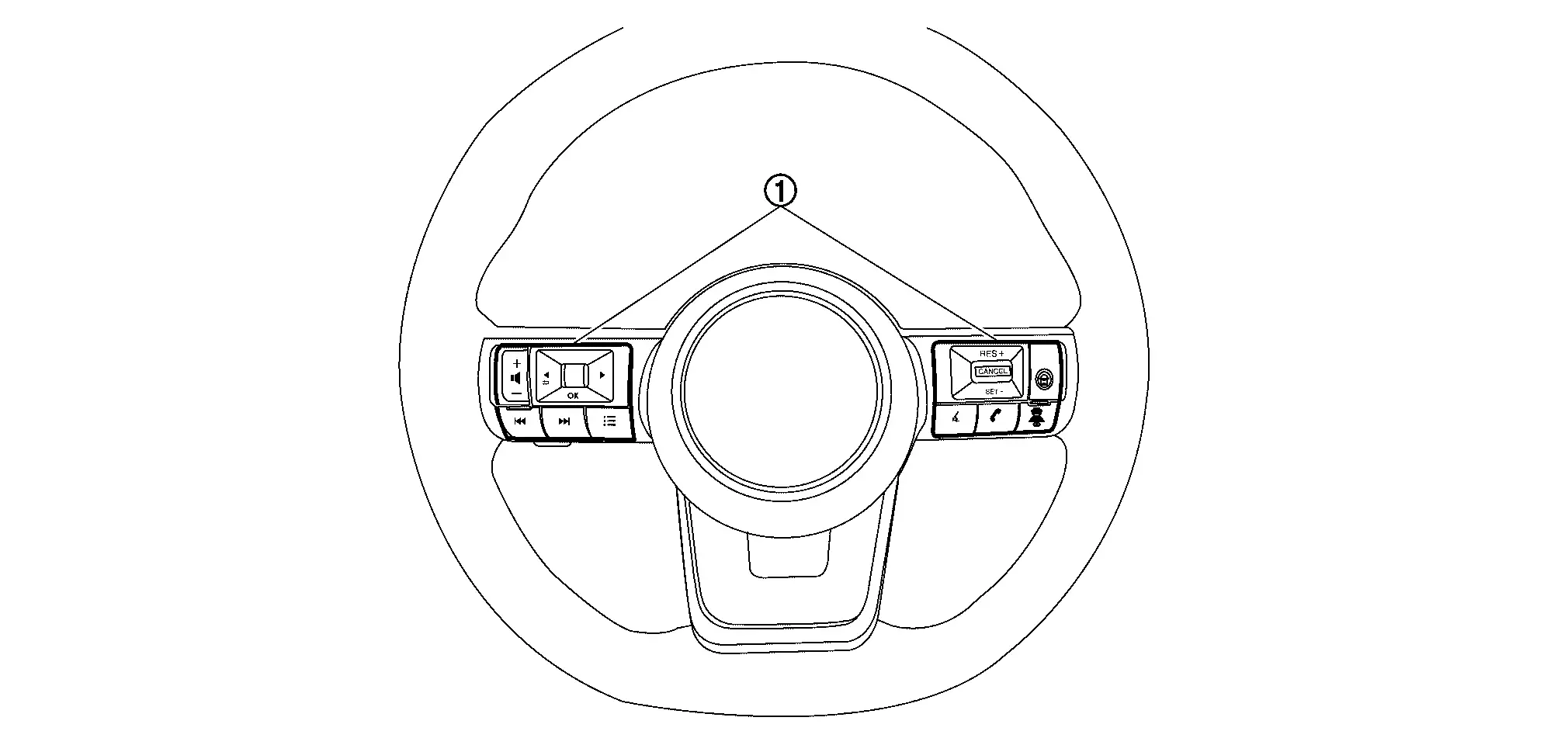
SWITCH NAME AND FUNCTION
No.Switch nameDescription
Steering switch
  1. Using the steering switch, select the [Settings] menu in the information display

  2. Select the [Driver Assistance] menu

  3. Select the [Emergency Brake] menu

  4. Select the [Rear] item to turn the system ON/OFF

SYSTEM DISPLAY

No.Switch nameDescription
RAB warning lamp
  • RAB warning lamp indicates that an malfunction condition is present in RAB system

  • When the RAB system turns OFF, the RAB warning lamp will illuminate.

RAB indicator Blinks when there is a possibility of a collision with the object backward

DISPLAY AND WARNING

System Display

ConditionActionDisplay on information displayWarning lampBuzzer
RAB OFF — — ON OFF
RAB ON There is not a possibility of a collision with the object backward — — OFF OFF
There is a possibility of a collision with the object backward Operates brake

White⇔Red

OFF Beep
RAB system malfunction The RAB system is automatically canceled*

Malfunction

See Owner’s Manual
ON Beep
When RAB system cannot be operated temporily The RAB system is automatically canceled* — Blink OFF

Handling Precaution Nissan Pathfinder SUV

Precautions for Rear Automatic Braking

PRECAUTIONS FOR REAR SONAR SENSORS

  • Always keep the rear sonar sensors clean.

  • If the rear sonar sensors are dirty, wipe them off with a soft cloth while being careful to not damage them.

  • Do not subject the area around the rear sonar sensors to strong impact.

  • Do not install any stickers (including transparent stickers) or accessories on the rear sonar sensors and their surrounding areas. This may cause a malfunction or improper operation.

PRECAUTIONS FOR RAB

Failure to follow the warnings and instructions for proper use of the RAB system could result in serious injury or death.

  • The RAB system is a supplemental aid to the driver. It is not a replacement for proper driving procedures. Always use the side and rear mirrors and turn and look in the direction to move before and while backing up. Never rely solely on the RAB system. It is the driver’s responsibility to stay alert, drive safely, and be in control of the Nissan Pathfinder vehicle at all times.

  • There is a limitation to the RAB system capability. The RAB system is not effective in all situations.

Listed below are the system limitations for the RAB system. Failure to follow the warnings and instructions for proper use of the RAB system could result in serious injury or death.

  • When the vehicle approaches an obstacle while the accelerator or brake pedal is depressed, the function may not operate or the start of the operation may be delayed. The RAB system may not operate or may not perform sufficiently due to Nissan Pathfinder vehicle conditions, driving conditions, the traffic environment, the weather, road surface conditions, etc. Do not wait for the system to operate. Operate the brake pedal as soon as necessary.

  • If it is necessary to override RAB operation, strongly press the accelerator pedal.

  • Always checks surroundings and turn to check what is behind the Nissan Pathfinder vehicle before and while backing up. The RAB system detects stationary objects behind the vehicle. The RAB system does not detect the following objects:

    • Moving objects

    • Low objects

    • Narrow objects

    • Wedge-shaped objects

    • Complex-shaped objects

    • Multiple object in close

    • Objects close to the bumper (less than approximately 1 ft [30 cm])

    • Objects that suddenly appear

    • Thin objects such as rope, wire, chain, etc.

  • The RAB system may not operate for pedestrians or animals.

  • The RAB system may not operate for the following obstacles:

    • Obstacles located high off the ground

    • Obstacles in a position offset from the Nissan Pathfinder vehicle

    • Obstacles, such as spongy materials or snow, that have soft outer surfaces and can easily absorb a sound wave

  • The RAB system may not operate in the following conditions:

    • There is rain, snow, ice, dirt, etc., attached to the sonar sensors.

    • A loud sound is heard in the area around the Nissan Pathfinder vehicle.

    • The surface of the obstacle is diagonal to the rear of the vehicle.

    • The sonar sensors or the area around them are extremely hot or cold.

  • The RAB system may unintentionally operate in the following conditions:

    • There is overgrown grass in the area around the Nissan Pathfinder vehicle.

    • There is a structure (e.g., a wall, toll gate equipment, a narrow tunnel, a parking lot gate) near the side of the Nissan Pathfinder vehicle.

    • There are bumps, protrusions, or manhole covers on the road surface.

    • The Nissan Pathfinder vehicle is driving through a draped flag or a curtain.

    • The vehicle is driving on a steep hill.

    • There is an accumulation of snow or ice behind the Nissan Pathfinder vehicle.

    • An ultrasonic wave source, such as another vehicle’s sonar, is near the vehicle.

  • Once the automatic brake control operates, it does not operate again if the Nissan Pathfinder vehicle approaches the same obstacle.

  • The automatic brake control can only operate for a short period of time. Therefore, the driver must depress the brake pedal.

  • In the following situations, the RAB system may not operate properly or may not function sufficiently:

    • The Nissan Pathfinder vehicle is driven in bad weather (rain, fog, snow, etc.).

    • The vehicle is driven on a steep hill.

    • The Nissan Pathfinder vehicle’s posture is changed (e.g., when driving over a bump).

    • The vehicle is driven on a slippery road.

    • The Nissan Pathfinder vehicle is turned sharply by turning the steering wheel fully.

    • Snow chains are used.

    • Wheels or tires other than NISSAN recommended are used.

    • The brakes are cold at low ambient temperatures or immediately after driving has started.

    • The braking force becomes poor due to wet brakes after driving through a puddle or washing the Nissan Pathfinder vehicle.

  • Turn the RAB system off in the following conditions to prevent the occurrence of an unexpected accident resulting from sudden system operation:

    • The Nissan Pathfinder vehicle is towed.

    • The vehicle is carried on a flatbed truck.

    • The vehicle is on the chassis dynamometer.

    • The Nissan Pathfinder vehicle drives on an uneven road surface.

    • Suspension parts other than those designated as genuine parts are used. (If the Nissan Pathfinder vehicle height or the vehicle body inclination is changed, the system may not detect an obstacle correctly.)

  • Excessive noise (e.g., audio system volume, an open Nissan Pathfinder vehicle window) interferes with the chime sound, and it may not be heard.

Diagnosis System (adas Control Unit 2) Nissan Pathfinder 2022

CONSULT Function (ICC/ADAS 2)

Refer to CONSULT Function (ICC/ADAS 2).