Brake Control System - Removal and Installation
- Front Wheel Sensor
- Rear Wheel Sensor
- Front Sensor Rotor
- Abs Actuator and Electric Unit (control Unit)
- Steering Angle Sensor
Front Wheel Sensor Nissan Pathfinder 2022
Exploded View

| 1. | Steering knuckle | 2. | Front wheel sensor | A. | Harness connector |
Removal and Installation
REMOVAL
Remove the front wheel and tire using power tool. Refer to Removal and Installation.
Remove the bolt and separate the front wheel sensor from the steering knuckle. Refer to Exploded View.
Disconnect the harness connector from the front wheel sensor.
Remove the front wheel sensor from the brackets.
INSTALLATION
Installation is in the reverse order of removal.

Rear Wheel Sensor Nissan Pathfinder SUV
Exploded View
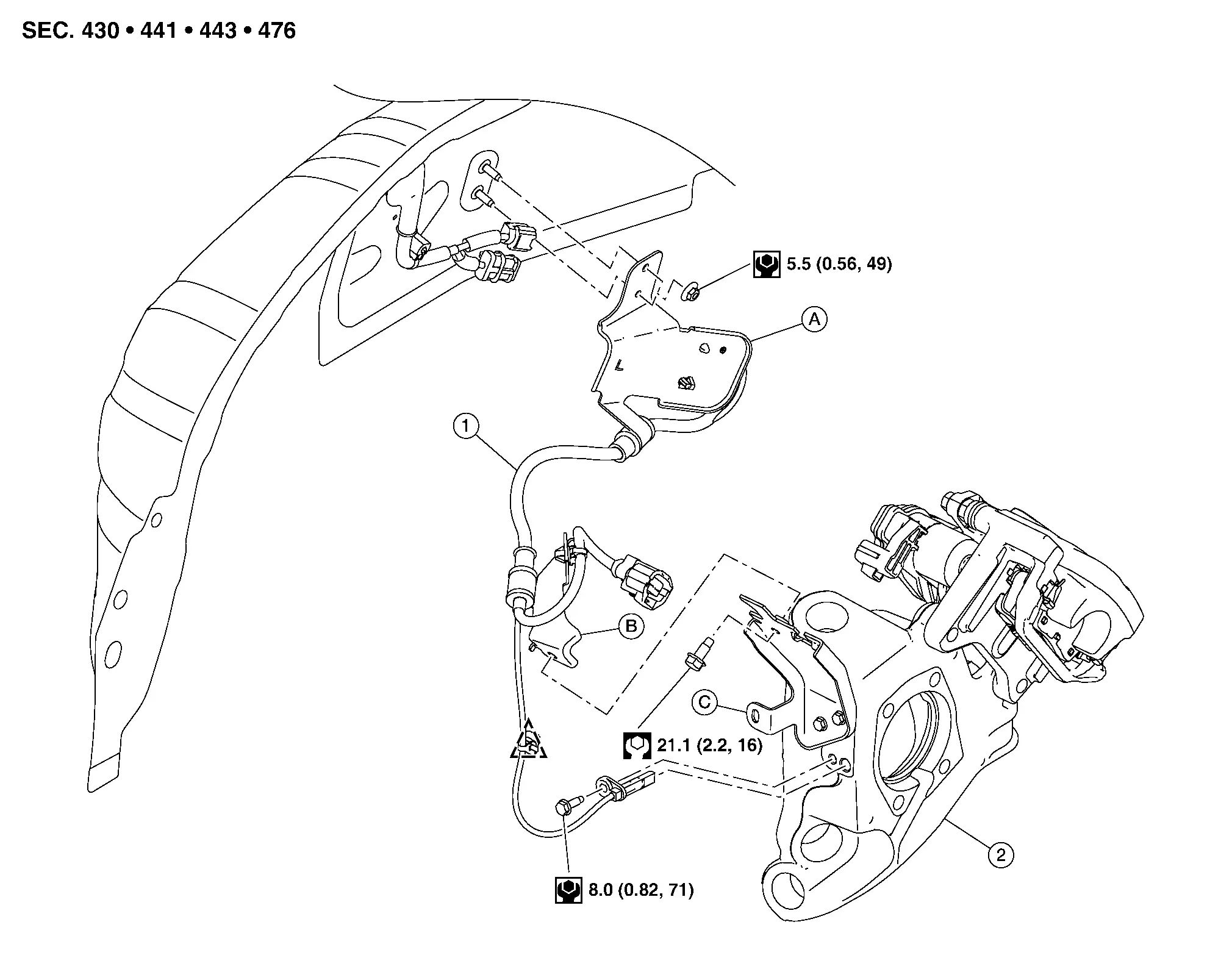
| 1. | Rear wheel sensor | 2. | Rear knuckle | A. | Upper bracket |
| B. | Middle bracket | C. | Lower bracket |  |
Clip |
Removal and Installation
REMOVAL
Remove the rear wheel and tire using power tool. Refer to Removal and Installation.
Remove the bolt and separate the rear wheel sensor from the rear knuckle. Refer to Exploded View.
Disconnect the harness connector from the rear brake caliper.
Using a suitable tool, separate the clip from the lower bracket.
Remove the bolt and separate the middle bracket from the lower bracket.
Remove the nuts and separate the upper bracket from the studs.
Disconnect the harness connectors from the harnesses at the rear wheelhouse. Remove the rear wheel sensor.
INSTALLATION
Installation is in the reverse order of removal.
Front Sensor Rotor Nissan Pathfinder 5th Gen
Removal and Installation
The front wheel sensor rotor is an integral part of the wheel hub and bearing and cannot be disassembled. Refer to Removal and Installation.
Abs Actuator and Electric Unit (control Unit) Nissan Pathfinder 5th Gen
Exploded View
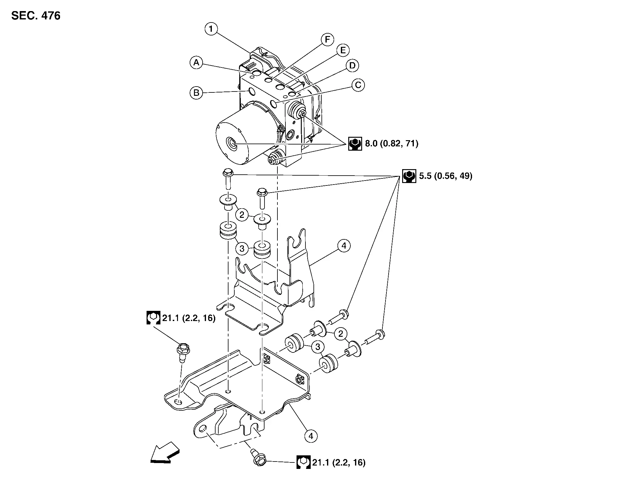
| 1. | ABS actuator and electric unit (control unit) | 2. | Insulator collar | 3. | Rubber bushing |
| 4. | Bracket | A. | To rear RH brake caliper. Refer to Exploded View. | B. | From master cylinder secondary side. Refer to Exploded View. |
| C. | From master cylinder primary side. Refer to Exploded View. | D. | To rear LH brake caliper. Refer to Exploded View. | E. | To front RH brake caliper. Refer to Exploded View. |
| F. | To front LH brake caliper. Refer to Exploded View. |  |
Front |
Removal and Installation
REMOVAL
Disconnect the negative battery terminal. Refer to Battery Disconnect.
Remove the cowl top extension. Refer to Removal and Installation.
Disconnect the harness connector from the ABS actuator and electric unit (control unit) by following the procedure described below:Push the connector position assurance. Move the lever down until the harness connector is unlocked. Disconnect the harness connector from the ABS actuator and electric unit (control unit).
Loosen the brake tube flare nuts using a flare nut wrench and separate the brake tubes from the ABS actuator and electric unit (control unit). Refer to Exploded View.
Loosen the nuts and remove the ABS actuator and electric unit (control unit) from the bracket. Refer to Exploded View.
Remove the low pressure pipe. Refer to Removal and Installation.
Raise the Nissan Pathfinder vehicle.
Remove the front under cover. Refer to Removal and Installation.
Remove the bolt from the lower front of the bracket.
Loosen the bolt on the lower rear of the bracket.
Lower the Nissan Pathfinder vehicle.
Remove the bolt from the upper front of the bracket.
Remove the bracket.
Remove the bolts from the bracket.
Remove the upper bracket from the lower bracket.
Remove the rubber bushings and the insulator collars.
INSTALLATION
Installation is in the reverse order of removal.
After work is completed, bleed air from brake tube. Refer to Bleeding Brake System.
Steering Angle Sensor Nissan Pathfinder
Exploded View
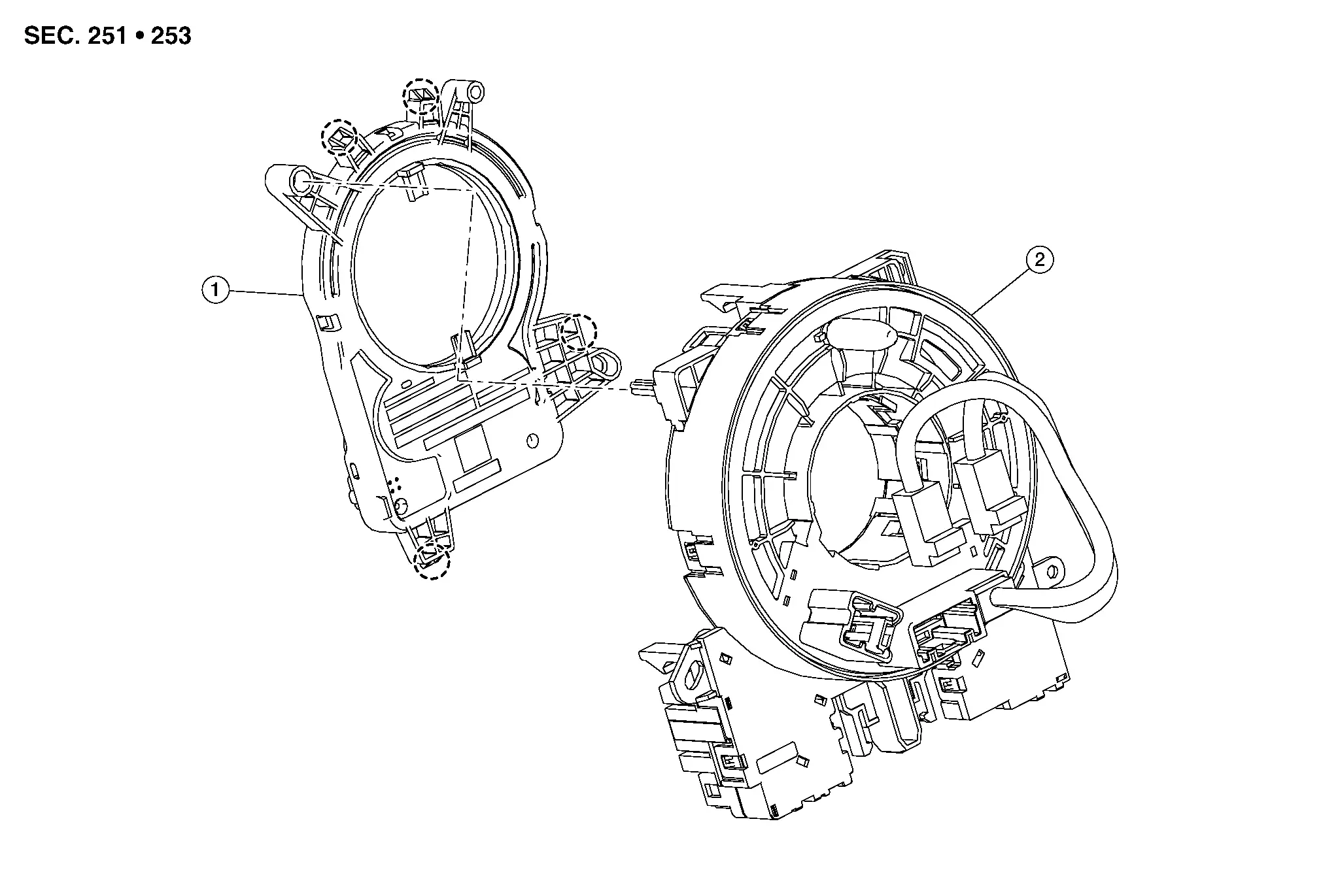
| 1. | Steering angle sensor | 2. | Spiral cable |  |
Pawl |
Removal and Installation
REMOVAL
Remove the spiral cable with the steering angle sensor from the combination switch. Refer to Removal and Installation.
Using a suitable tool, release the pawls and remove the steering angle sensor from the spiral cable. Refer to Exploded View.
INSTALLATION
Installation is in the reverse order of removal.