Lan System - System Description
- Component Parts
- System
Component Parts Nissan Pathfinder
Component Parts Location
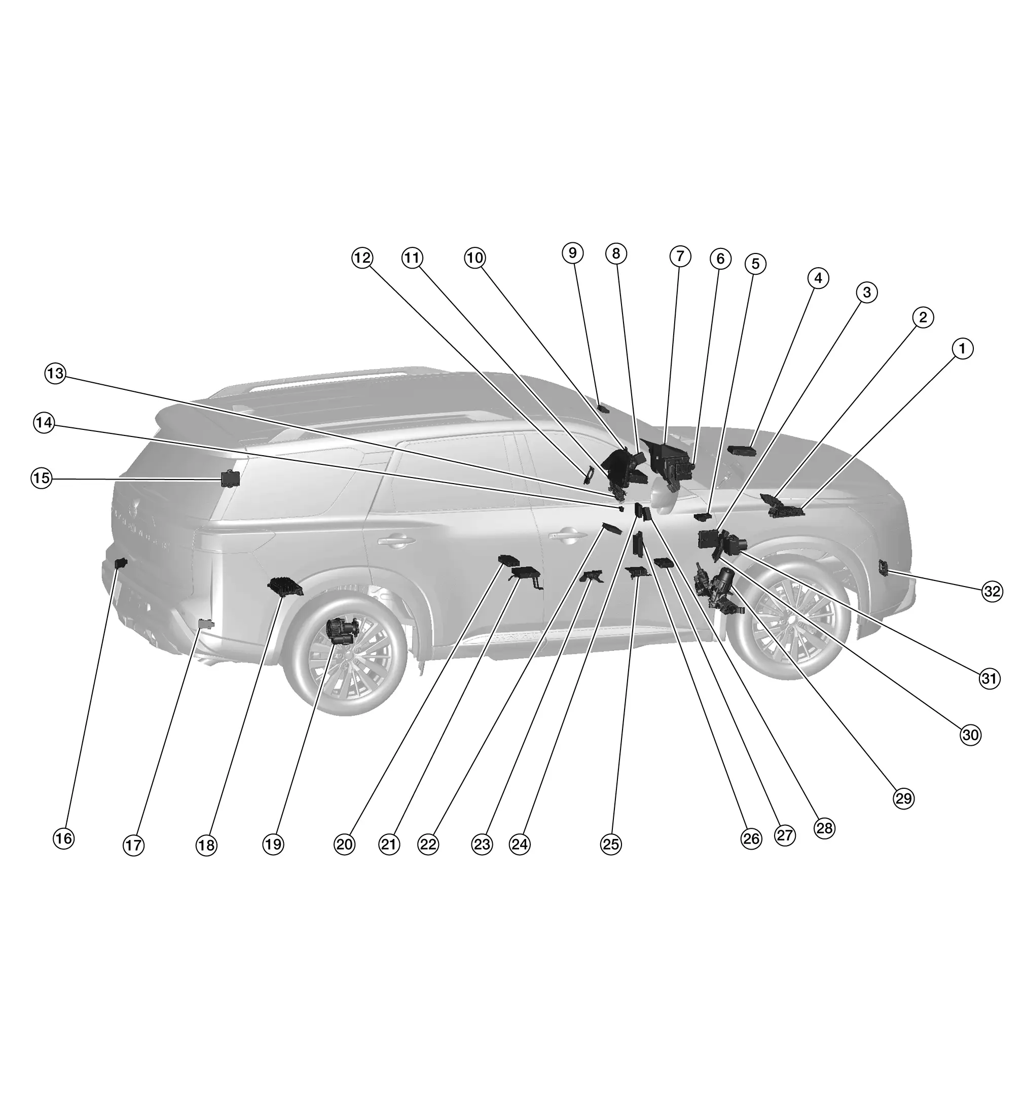
 |
ECM |  |
Electric intake valve timing control module |  |
A/C auto amp. |
 |
IPDM E/R |  |
Intelligent Key unit |  |
8CH CAN gateway |
 |
Head Up Display unit |  |
Chassis control module |  |
Front camera unit |
 |
Combination meter |  |
AV control unit |  |
Steering angle sensor |
 |
BCM |  |
Data link connector |  |
Automatic back door control unit |
 |
Side radar LH |  |
Side radar RH |  |
BOSE speaker amp. |
 |
4WD control unit |  |
Driver seat control unit |  |
Around view monitor control unit |
 |
Wireless charger unit |  |
Electric shift control module |  |
Sonar control unit |
 |
Air bag diagnosis sensor unit |  |
ADAS control unit 2 |  |
TCU |
 |
Automatic drive positioner control unit |  |
EPS control unit |  |
TCM |
 |
ABS actuator and electric unit (control unit) |  |
Distance sensor |
System Nissan Pathfinder
Can Communication System
System Description
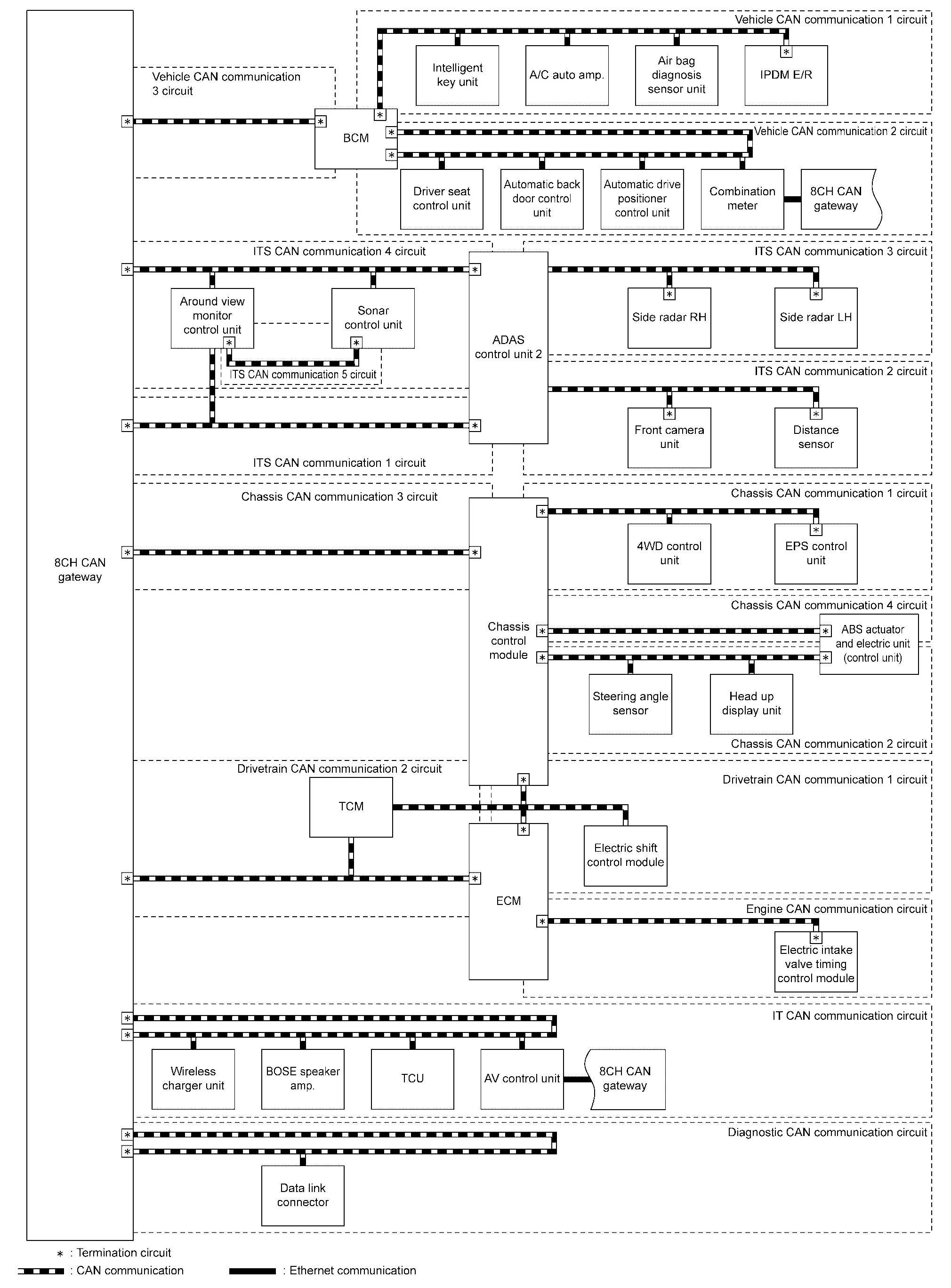
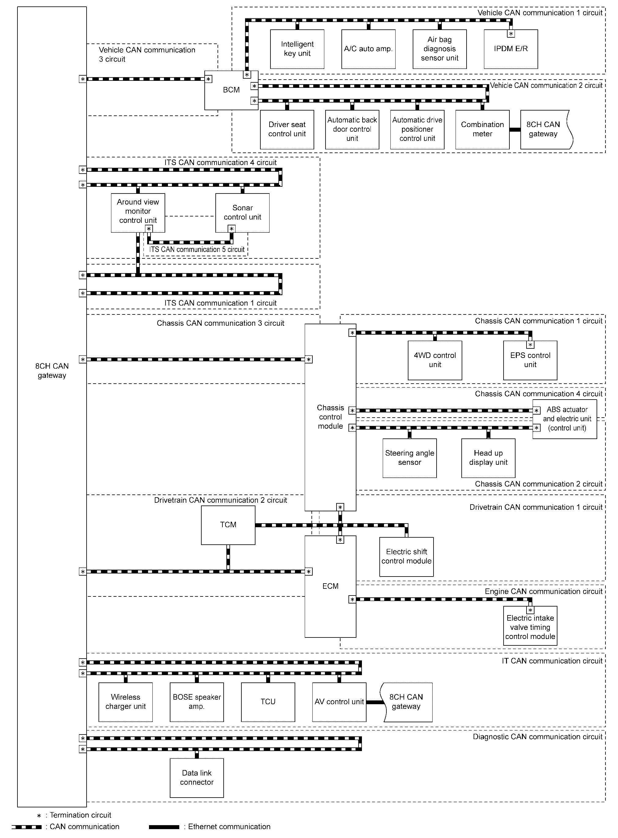
SYSTEM DIAGRAM
With Automatic Emergency Braking
Without Automatic Emergency Braking
DESCRIPTION
CAN (Controller Area Network) is a serial communication line for real time application. It is an on-Nissan Pathfinder vehicle multiplex communication line with high data communication speed and excellent error detection ability. Many electronic control units are equipped onto a Nissan Pathfinder vehicle, and each control unit shares information and links with other control units during operation (not independent). In CAN communication, control units are connected with 2 communication lines (CAN-H line, CAN-L line) allowing a high rate of information transmission with less wiring. Each control unit transmits/receives data but selectively reads required data only.
The following control units connect to CAN communication circuits.
CAN communication circuit Control unit Reference Between the following circuits.
Nissan Pathfinder Vehicle CAN communication 1 circuit
Vehicle CAN communication 2 circuit
Nissan Pathfinder Vehicle CAN communication 3 circuit
BCM System Description Between the following circuits.
Nissan Pathfinder Vehicle CAN communication 3 circuit
ITS CAN communication 1 circuit
ITS CAN communication 4 circuit
Chassis CAN communication 3 circuit
Drivetrain CAN communication 2 circuit
IT CAN communication circuit
Diagnostic CAN communication circuit
8CH CAN gateway 8CH CAN Gateway Between the following circuits. (With Automatic Emergency Braking)
ITS CAN communication 1 circuit
ITS CAN communication 2 circuit
ITS CAN communication 3 circuit
ITS CAN communication 4 circuit
ADAS control unit 2 ADAS Control Unit 2 Between the following circuits.
Chassis CAN communication 1 circuit
Chassis CAN communication 2 circuit
Chassis CAN communication 3 circuit
Chassis CAN communication 4 circuit
Drivetrain CAN communication 1 circuit
Chassis control module Chassis Control Module Between the following circuits. (with Intelligent around view monitor system)
ITS CAN communication 1 circuit
ITS CAN communication 4 circuit
ITS CAN communication 5 circuit
Around view monitor control unit Around View Monitor Control Unit ITS CAN communication 4 circuit ⇔ ITS CAN communication 5 circuit Sonar control unit Sonar Sensor Chassis CAN communication 2 circuit ⇔ Chassis CAN communication 4 circuit ABS actuator and electric unit (control unit) ABS Actuator and Electric Unit (Control Unit) Between the following circuits.
Drivetrain CAN communication 1 circuit
Drivetrain CAN communication 2 circuit
Engine CAN communication circuit
ECM ECM (With Barometric Pressure Sensor) Drivetrain CAN communication 1 circuit ⇔ Drivetrain CAN communication 2 circuit TCM TCM
CAN Communication Signal Generation
Termination circuits (resistors) are connected across the CAN communication system. When transmitting a CAN communication signal, each control unit passes a current to the CAN-H line and the current returns to the CAN-L line.

The current flows separately into the termination circuits connected across the CAN communication system and the termination circuits drop voltage to generate a potential difference between the CAN-H line and the CAN-L line.

The system produces digital signals for signal communications, by using the potential difference.

The Construction of CAN Communication Signal (Message)

| No. | Message name | Description |
|---|---|---|
| 1 | Start of frame (1 bit) | Start of message. |
| 2 | Arbitration of field (11 bit) | Priorities of message-sending are shown when there is a possibility that multiple messages are sent at the same time. |
| 3 | Control field (6 bit) | Signal quantity in data field is shown. |
| 4 | Data field (0-64 bit) | Actual signal is shown. |
| 5 | CRC field (16 bit) |
|
| 6 | ACK field (2 bit) | The completion of normal reception is sent to the transmitting unit. |
| 7 | End of frame (7 bit) | End of message. |
CAN Communication Line
The CAN communication line is a twisted pair wire consisting of strands of CAN-H  and CAN-L
 and has noise immunity.

Since the CAN-H line and the CAN-L line are always adjacent to each other, the same degree of noise occurs, respectively, when a noise  occurs. Although the noise changes the voltage, the potential difference
 between the CAN-H line and the CAN-L line is insensitive to noise. Therefore, noise-resistant signals can be obtained.

CAN Signal Communications
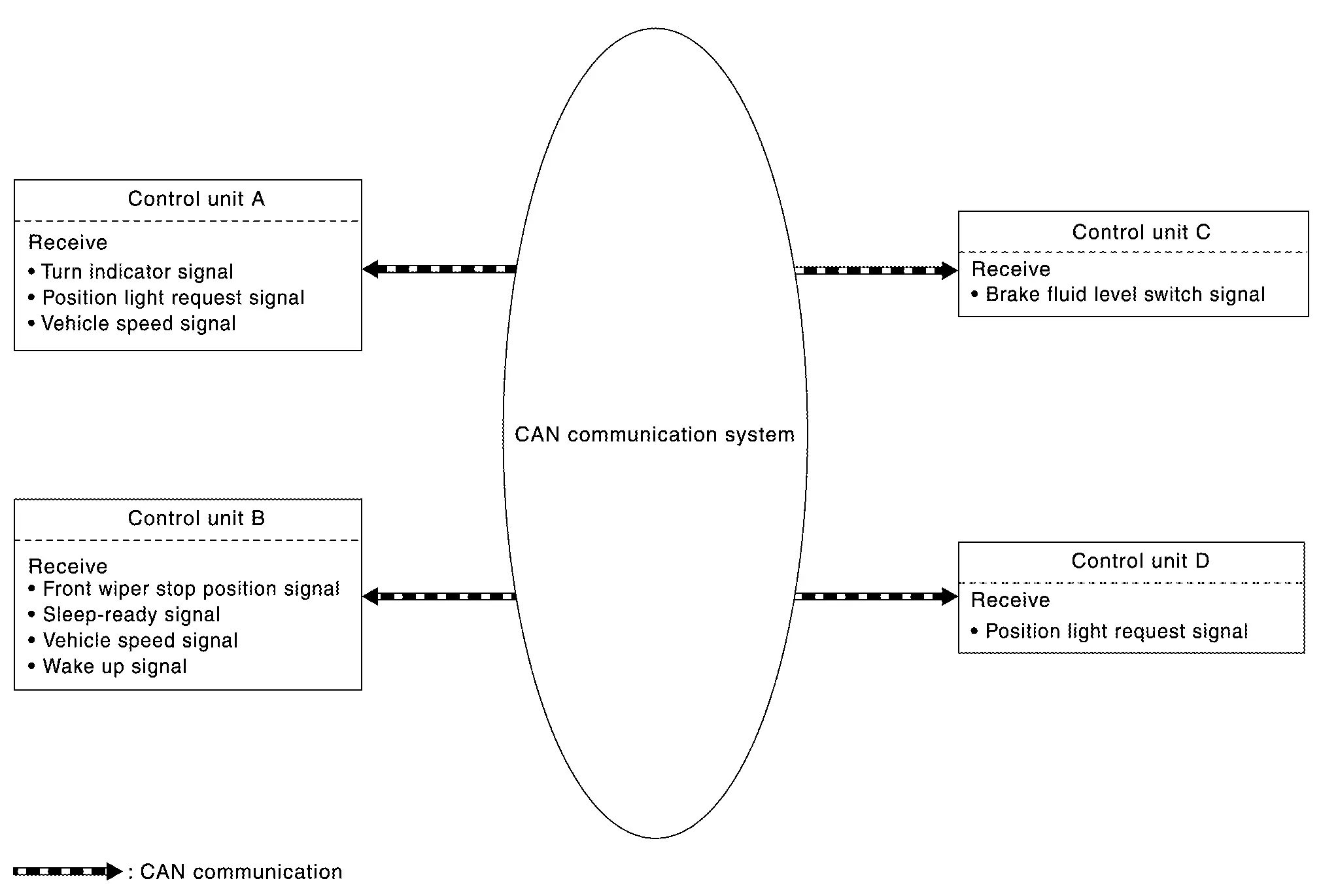
Each control unit of the CAN communication system transmits signals through the CAN communication control circuit included in the control unit and receives only necessary signals from each control unit to perform various kinds of control.
Example: Transmitted signals
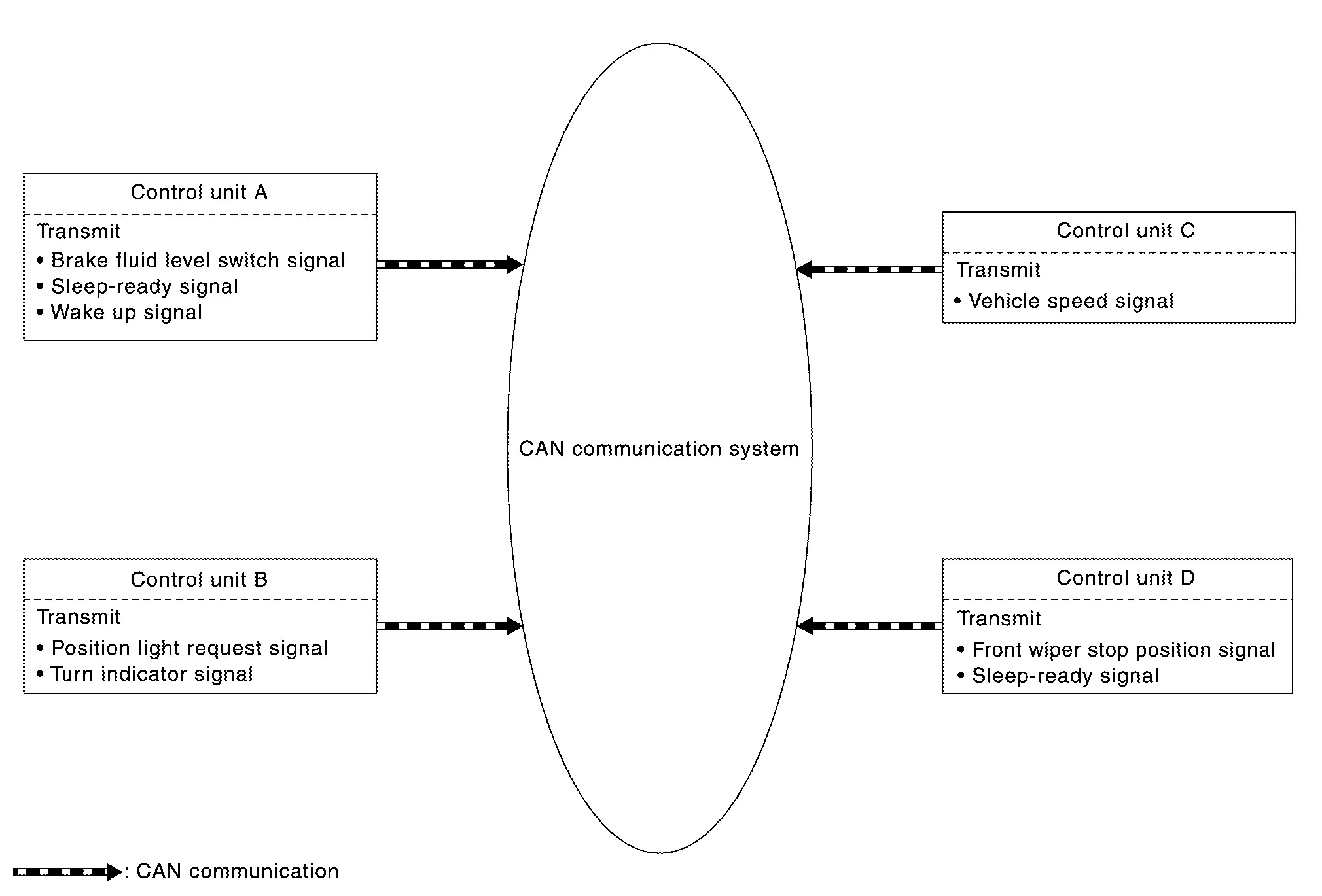
Example: Received signals
CAN Communication Control Circuit
CAN communication control circuit is incorporated into the control unit and transmits/receives CAN communication signals.
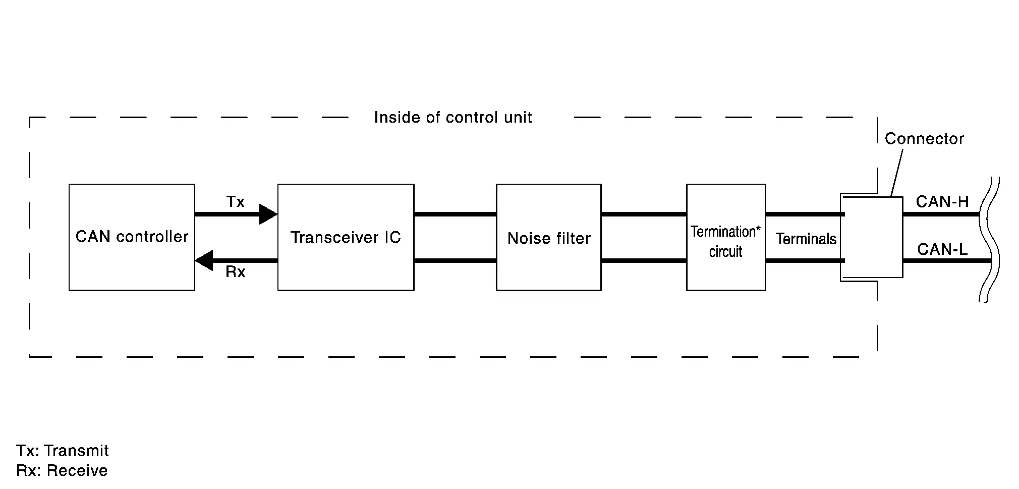
| Component | System description |
|---|---|
| CAN controller | It controls CAN communication signal transmission and reception, error detection, etc. |
| Transceiver IC | It converts digital signal into CAN communication signal, and CAN communication signal into digital signal. |
| Noise filter | It eliminates noise of CAN communication signal. |
Termination circuit* (Resistance of approx. 120 Ω) |
Generates a potential difference between CAN-H and CAN-L. |
*: These are the only control units wired with both ends of CAN communication system.
CAN System Specification Chart
Determine CAN system type from the following specification chart.
| Body type | Wagon | |||||||||||||||||||||
|---|---|---|---|---|---|---|---|---|---|---|---|---|---|---|---|---|---|---|---|---|---|---|
| Axle | 2WD | 4WD | ||||||||||||||||||||
| Engine | VQ35DD | |||||||||||||||||||||
| Transmission | A/T | |||||||||||||||||||||
| Brake control | VDC | |||||||||||||||||||||
| Forward Emergency Braking | X | X | X | X | X | X | X | X | X | X | X | X | X | X | X | X | X | X | X | X | ||
| Telematics system | X | X | X | X | X | X | X | X | X | X | X | X | X | X | X | X | X | X | X | X | ||
| Automatic back door control system | X | X | X | X | X | X | X | X | X | X | X | X | X | X | X | X | X | X | X | |||
| Intelligent around view monitor | X | X | X | X | X | X | X | X | X | X | X | X | X | X | X | X | ||||||
| Wireless charger unit | X | X | X | X | X | X | X | X | X | X | X | |||||||||||
| BOSE audio | X | X | X | X | X | X | X | X | X | |||||||||||||
| Automatic drive positioner system (seat position) | X | X | X | X | X | X | X | X | ||||||||||||||
| Head Up Display | X | X | X | X | ||||||||||||||||||
| Automatic drive positioner system (steering column position) | X | X | ||||||||||||||||||||
| CAN system type | 1 | 2 | 3 | 4 | 5 | 6 | 7 | 8 | 9 | 10 | 11 | 12 | 13 | 14 | 15 | 16 | 17 | 18 | 19 | 20 | 21 | 22 |
| Nissan Pathfinder Vehicle CAN Communication unit | ||||||||||||||||||||||
| BCM | X | X | X | X | X | X | X | X | X | X | X | X | X | X | X | X | X | X | X | X | X | X |
| Intelligent key unit | X | X | X | X | X | X | X | X | X | X | X | X | X | X | X | X | X | X | X | X | X | X |
| A/C auto amp. | X | X | X | X | X | X | X | X | X | X | X | X | X | X | X | X | X | X | X | X | X | X |
| Air bag diagnosis sensor unit | X | X | X | X | X | X | X | X | X | X | X | X | X | X | X | X | X | X | X | X | X | X |
| IPDM E/R | X | X | X | X | X | X | X | X | X | X | X | X | X | X | X | X | X | X | X | X | X | X |
| Combination meter | X | X | X | X | X | X | X | X | X | X | X | X | X | X | X | X | X | X | X | X | X | X |
| Automatic back door control unit | X | X | X | X | X | X | X | X | X | X | X | X | X | X | X | X | X | X | X | |||
| Driver seat control unit | X | X | X | X | X | X | X | X | ||||||||||||||
| Automatic drive positioner control unit | X | X | ||||||||||||||||||||
| 8CH CAN gateway | X | X | X | X | X | X | X | X | X | X | X | X | X | X | X | X | X | X | X | X | X | X |
| ITS CAN communication unit | ||||||||||||||||||||||
| 8CH CAN gateway | X | X | X | X | X | X | X | X | X | X | X | X | X | X | X | X | X | X | X | X | X | X |
| ADAS control unit 2 | X | X | X | X | X | X | X | X | X | X | X | X | X | X | X | X | X | X | X | X | ||
| Around view monitor control unit | X | X | X | X | X | X | X | X | X | X | X | X | X | X | X | X | ||||||
| Distance sensor | X | X | X | X | X | X | X | X | X | X | X | X | X | X | X | X | X | X | X | X | ||
| Front camera unit | X | X | X | X | X | X | X | X | X | X | X | X | X | X | X | X | X | X | X | X | ||
| Side radar LH | X | X | X | X | X | X | X | X | X | X | X | X | X | X | X | X | X | X | X | X | ||
| Side radar RH | X | X | X | X | X | X | X | X | X | X | X | X | X | X | X | X | X | X | X | X | ||
| Sonar control unit | X | X | X | X | X | X | X | X | X | X | X | X | X | X | X | X | X | X | X | X | X | X |
| Chassis CAN communication unit | ||||||||||||||||||||||
| Chassis control module | X | X | X | X | X | X | X | X | X | X | X | X | X | X | X | X | X | X | X | X | X | X |
| 4WD control unit | X | X | X | X | X | X | X | X | X | X | X | X | ||||||||||
| EPS control unit | X | X | X | X | X | X | X | X | X | X | X | X | X | X | X | X | X | X | X | X | X | X |
| Head Up Display unit | X | X | X | X | ||||||||||||||||||
| Steering angle sensor | X | X | X | X | X | X | X | X | X | X | X | X | X | X | X | X | X | X | X | X | X | X |
| ABS actuator and electric unit (control unit) | X | X | X | X | X | X | X | X | X | X | X | X | X | X | X | X | X | X | X | X | X | X |
| 8CH CAN gateway | X | X | X | X | X | X | X | X | X | X | X | X | X | X | X | X | X | X | X | X | X | X |
| Drivetrain CAN communication unit | ||||||||||||||||||||||
| ECM | X | X | X | X | X | X | X | X | X | X | X | X | X | X | X | X | X | X | X | X | X | X |
| TCM | X | X | X | X | X | X | X | X | X | X | X | X | X | X | X | X | X | X | X | X | X | X |
| Electric shift control module | X | X | X | X | X | X | X | X | X | X | X | X | X | X | X | X | X | X | X | X | X | X |
| Chassis control module | X | X | X | X | X | X | X | X | X | X | X | X | X | X | X | X | X | X | X | X | X | X |
| 8CH CAN gateway | X | X | X | X | X | X | X | X | X | X | X | X | X | X | X | X | X | X | X | X | X | X |
| IT CAN communication unit | ||||||||||||||||||||||
| 8CH CAN gateway | X | X | X | X | X | X | X | X | X | X | X | X | X | X | X | X | X | X | X | X | X | X |
| TCU | X | X | X | X | X | X | X | X | X | X | X | X | X | X | X | X | X | X | X | X | ||
| AV control unit | X | X | X | X | X | X | X | X | X | X | X | X | X | X | X | X | X | X | X | X | X | X |
| Wireless charger unit | X | X | X | X | X | X | X | X | X | X | X | |||||||||||
| BOSE speaker amp. | X | X | X | X | X | X | X | X | X | |||||||||||||
| Engine CAN communication unit | ||||||||||||||||||||||
| ECM | X | X | X | X | X | X | X | X | X | X | X | X | X | X | X | X | X | X | X | X | X | X |
| Electric intake valve timing control module | X | X | X | X | X | X | X | X | X | X | X | X | X | X | X | X | X | X | X | X | X | X |
| Diagnostic CAN communication unit | ||||||||||||||||||||||
| 8CH CAN gateway | X | X | X | X | X | X | X | X | X | X | X | X | X | X | X | X | X | X | X | X | X | X |
| Data link connector | X | X | X | X | X | X | X | X | X | X | X | X | X | X | X | X | X | X | X | X | X | X |
×: Applicable
Vehicle Equipment Identification Information

 |
Front camera unit |  |
Telematics switch |  |
Automatic back door switch |
 |
Side camera RH |  |
Wireless charger indicator |  |
Front tweeter RH (BOSE logo) |
 |
Seat memory switch |  |
Head Up Display switch |  |
ADP (automatic drive positioner) steering switch |
 |
With Forward Emergency Braking |  |
With telematics system |  |
With automatic back door system |
 |
With Intelligent around view monitor system |  |
With wireless charger |  |
With BOSE audio system |
 |
With automatic drive positioner system (seat position) |  |
With Head Up Display |  |
With automatic drive positioner system (steering column position) |
CAN Communication Signal Chart
Refer to How to Use CAN Communication Signal Chart for how to use CAN communication signal chart.
T: Transmit R: Receive
| Signal name | BCM | HFM | HVAC | A-BAG | IPDM-E | M&A | SC CM | ADP | PWBD | AVM | ICC 2 | LASER | LANE | RDR-L | RDR-R | SONAR | CCM | 4WD | EPS/DAST 3 | E-HUD | STRG | ABS | ECM | TCM | E-SHIFT | EVTC | WL CHG | AV | IVC | A-AMP. |
|---|---|---|---|---|---|---|---|---|---|---|---|---|---|---|---|---|---|---|---|---|---|---|---|---|---|---|---|---|---|---|
| Back door open request signal | T | R | ||||||||||||||||||||||||||||
| Back door switch signal | T | R | R | |||||||||||||||||||||||||||
| Brake pedal position switch signal | T | R | ||||||||||||||||||||||||||||
| Brake pedal status signal | T | R | R | |||||||||||||||||||||||||||
| Daytime running light request signal | T | R | ||||||||||||||||||||||||||||
| Delivery mode signal | T | R | ||||||||||||||||||||||||||||
| Dimmer signal | T | R | R | R | R | |||||||||||||||||||||||||
| Door lock status signal | T | R | R | |||||||||||||||||||||||||||
| Door switch (driver side) signal | T | R | R | |||||||||||||||||||||||||||
| Door switch signal | T | R | R | R | R | R | R | R | ||||||||||||||||||||||
| Drive mode switch signal | T | R | ||||||||||||||||||||||||||||
| Driver seatbelt switch malfunction signal | T | R | ||||||||||||||||||||||||||||
| ECO advice signal | T | R | ||||||||||||||||||||||||||||
| Front fog light request signal | T | R | R | |||||||||||||||||||||||||||
| Front fog light status signal | T | R | ||||||||||||||||||||||||||||
| Front wiper request signal | T | R | R | |||||||||||||||||||||||||||
| Front washer pump request signal | T | R | ||||||||||||||||||||||||||||
| Hazard warning lamp status signal | T | R | ||||||||||||||||||||||||||||
| High beam assist indicator signal | T | R | ||||||||||||||||||||||||||||
| High beam request signal | T | R | R | |||||||||||||||||||||||||||
| High beam status signal | T | R | ||||||||||||||||||||||||||||
| Horn request signal | T | R | ||||||||||||||||||||||||||||
| I-key exist information signal | T | R | ||||||||||||||||||||||||||||
| Key ID signal | T | R | ||||||||||||||||||||||||||||
| Key ID verification request signal | T | R | ||||||||||||||||||||||||||||
| Light reminder warning signal | T | R | ||||||||||||||||||||||||||||
| Low beam request signal | T | R | R | |||||||||||||||||||||||||||
| Low beam status signal | T | R | ||||||||||||||||||||||||||||
| Low tire pressure warning lamp signal | T | R | ||||||||||||||||||||||||||||
| Low tire pressure wheel location signal | T | R | ||||||||||||||||||||||||||||
| Paddle shifter shift down signal | T | R | ||||||||||||||||||||||||||||
| Paddle shifter shift up signal | T | R | ||||||||||||||||||||||||||||
| Passing request signal | T | R | ||||||||||||||||||||||||||||
| Position light request signal | T | R | R | R | ||||||||||||||||||||||||||
| Position light status signal | T | R | ||||||||||||||||||||||||||||
| Rear washer pump request signal | T | R | ||||||||||||||||||||||||||||
| Rear window defogger feedback signal | T | R | ||||||||||||||||||||||||||||
| Remote engine start status signal | T | R | ||||||||||||||||||||||||||||
| Seat belt buckle switch (driver side) signal | T | R | R | |||||||||||||||||||||||||||
| Seat belt buckle switch (front LH) signal | T | R | R | |||||||||||||||||||||||||||
| Sleep wake up signal | T | R | R | R | R | R | R | R | R | R | R | R | R | |||||||||||||||||
| Stop lamp switch signal | T | R | R | R | R | R | R | |||||||||||||||||||||||
| Stop/Start OFF switch signal | T | R | ||||||||||||||||||||||||||||
| TPMS malfunction warning lamp signal | T | R | ||||||||||||||||||||||||||||
| Turn indicator signal | T | R | R | R | R | R | ||||||||||||||||||||||||
| T | R | |||||||||||||||||||||||||||||
| Nissan Pathfinder Vehicle status signal | T | R | R | R | ||||||||||||||||||||||||||
| Charge stop request signal | T | R | ||||||||||||||||||||||||||||
| Door lock/unlock request signal | R | T | ||||||||||||||||||||||||||||
| Key ID verification completed signal | T | R | ||||||||||||||||||||||||||||
| Meter display signal | T | R | ||||||||||||||||||||||||||||
| R | T | |||||||||||||||||||||||||||||
| R | T | |||||||||||||||||||||||||||||
| R | T | |||||||||||||||||||||||||||||
| R | T | |||||||||||||||||||||||||||||
| R | T | |||||||||||||||||||||||||||||
| Push-button ignition switch status signal | R | T | ||||||||||||||||||||||||||||
| User identification signal | T | R | ||||||||||||||||||||||||||||
| Wireless charge current signal | T | R | ||||||||||||||||||||||||||||
| A/C ON signal | T | R | ||||||||||||||||||||||||||||
| Blower fan ON signal | R | T | R | |||||||||||||||||||||||||||
| Cooling fan request signal | T | R | ||||||||||||||||||||||||||||
| ECV control signal | T | R | ||||||||||||||||||||||||||||
| Idle up request signal | T | R | ||||||||||||||||||||||||||||
| PTC thermal request signal | R | T | ||||||||||||||||||||||||||||
| Rear window defogger request signal | R | T | ||||||||||||||||||||||||||||
| Stop/Start permit signal | T | R | ||||||||||||||||||||||||||||
| T | R | |||||||||||||||||||||||||||||
| T | R | |||||||||||||||||||||||||||||
| T | R | |||||||||||||||||||||||||||||
| T | R | |||||||||||||||||||||||||||||
| R | T | |||||||||||||||||||||||||||||
| Car crush information signal | R | T | R | |||||||||||||||||||||||||||
| Occupant detection signal | T | R | ||||||||||||||||||||||||||||
| SRS air bag warning lamp signal | T | R | ||||||||||||||||||||||||||||
| Seat belt buckle switch (rear) signal | T | R | ||||||||||||||||||||||||||||
| Seat belt warning (front RH) signal | T | R | ||||||||||||||||||||||||||||
| A/C compressor feedback signal | R | T | ||||||||||||||||||||||||||||
| Auto ACC status signal | T | R | ||||||||||||||||||||||||||||
| T | R | |||||||||||||||||||||||||||||
| Battery warning request signal (IPDM E/R) | T | R | ||||||||||||||||||||||||||||
| Front wiper status signal | R | T | ||||||||||||||||||||||||||||
| Front wiper stop position signal | R | T | ||||||||||||||||||||||||||||
| Generator voltage request signal | T | R | ||||||||||||||||||||||||||||
| Headlamp warning signal | T | R | ||||||||||||||||||||||||||||
| Hood switch signal | R | T | R | |||||||||||||||||||||||||||
| Ignition ON signal | R | T | ||||||||||||||||||||||||||||
| T | R | R | R | |||||||||||||||||||||||||||
| Ignition switch ON signal | T | R | ||||||||||||||||||||||||||||
| Reverse position signal | R | T | ||||||||||||||||||||||||||||
| Sleep-ready signal | R | T | ||||||||||||||||||||||||||||
| R | T | |||||||||||||||||||||||||||||
| R | T | |||||||||||||||||||||||||||||
| R | T | |||||||||||||||||||||||||||||
| R | T | |||||||||||||||||||||||||||||
| R | T | |||||||||||||||||||||||||||||
| R | T | |||||||||||||||||||||||||||||
| R | T | |||||||||||||||||||||||||||||
| R | T | |||||||||||||||||||||||||||||
| Starter cut relay status signal | R | T | R | |||||||||||||||||||||||||||
| Starter relay status signal | T | R | R | |||||||||||||||||||||||||||
| Starter status signal | T | R | ||||||||||||||||||||||||||||
| Ambient temperature signal | R | R | T | |||||||||||||||||||||||||||
| Automatic back door setting signal | T | R | ||||||||||||||||||||||||||||
| Brake fluid level switch signal | T | R | ||||||||||||||||||||||||||||
| Driver seat belt switch signal | T | R | ||||||||||||||||||||||||||||
| HUD setting signal | T | R | ||||||||||||||||||||||||||||
| MOD setting signal | T | R | ||||||||||||||||||||||||||||
| Parking brake status signal | R | T | R | R | R | R | R | |||||||||||||||||||||||
| Remaining distance reset request signal | T | R | ||||||||||||||||||||||||||||
| System selection signal | T | R | R | R | R | R | ||||||||||||||||||||||||
| Nissan Pathfinder Vehicle speed display signal | T | R | ||||||||||||||||||||||||||||
| R | T | R | ||||||||||||||||||||||||||||
| Memory guidance display request signal | R | T | ||||||||||||||||||||||||||||
| Mirror control signal | R | T | ||||||||||||||||||||||||||||
| MOD setting status signal | R | T | ||||||||||||||||||||||||||||
| View change signal | T | R | ||||||||||||||||||||||||||||
| AEB warning lamp signal | R | T | ||||||||||||||||||||||||||||
| Brake fluid pressure control signal | T | R | ||||||||||||||||||||||||||||
| Brake torque request signal | T | R | ||||||||||||||||||||||||||||
| T | R | |||||||||||||||||||||||||||||
| R | T | |||||||||||||||||||||||||||||
| Brake wheel torque signal | T | R | R | |||||||||||||||||||||||||||
| R | T | |||||||||||||||||||||||||||||
| BSW indicator dimmer signal | T | R | R | |||||||||||||||||||||||||||
| BSW indicator signal | T | R | R | |||||||||||||||||||||||||||
| Display signal | T | R | ||||||||||||||||||||||||||||
| T | R | |||||||||||||||||||||||||||||
| ICC operation signal | T | R | ||||||||||||||||||||||||||||
| ProPILOT Assist operation signal | T | R | R | |||||||||||||||||||||||||||
| RAB warning signal | R | T | ||||||||||||||||||||||||||||
| RAB warning lamp signal | R | T | ||||||||||||||||||||||||||||
| Target yaw moment signal | T | R | ||||||||||||||||||||||||||||
| Wheel torque request signal | T | R | ||||||||||||||||||||||||||||
| Yaw moment request signal | T | R | ||||||||||||||||||||||||||||
| T | R | |||||||||||||||||||||||||||||
| Distance sensor signal | R | T | ||||||||||||||||||||||||||||
| Detected lane condition signal | R | T | ||||||||||||||||||||||||||||
| Driver assistance buzzer signal | R | T | ||||||||||||||||||||||||||||
| R | T | |||||||||||||||||||||||||||||
| R | T | |||||||||||||||||||||||||||||
| Motor operation signal | R | T | ||||||||||||||||||||||||||||
| Pedestrian ahead signal | R | T | ||||||||||||||||||||||||||||
| Nissan Pathfinder Vehicle ahead signal | R | T | ||||||||||||||||||||||||||||
| Nissan Pathfinder Vehicle detection signal | R | T | ||||||||||||||||||||||||||||
| R | T | |||||||||||||||||||||||||||||
| Parking sensor error signal | R | T | ||||||||||||||||||||||||||||
| Sonar indicator signal | R | R | T | |||||||||||||||||||||||||||
| Sonar sensor signal | R | T | ||||||||||||||||||||||||||||
| Active ride control signal | T | R | ||||||||||||||||||||||||||||
| Automatic brake hold indicator lamp signal | R | T | ||||||||||||||||||||||||||||
| Automatic brake hold operation request signal | T | R | ||||||||||||||||||||||||||||
| Automatic brake hold release request signal | T | R | ||||||||||||||||||||||||||||
| Chassis control module malfunction signal | T | R | ||||||||||||||||||||||||||||
| Drive mode signal | R | T | ||||||||||||||||||||||||||||
| R | T | |||||||||||||||||||||||||||||
| T | R | |||||||||||||||||||||||||||||
| T | R | |||||||||||||||||||||||||||||
| T | R | |||||||||||||||||||||||||||||
| T | R | |||||||||||||||||||||||||||||
| Electric parking brake operation request signal | T | R | ||||||||||||||||||||||||||||
| T | R | |||||||||||||||||||||||||||||
| Intelligent engine brake signal | T | R | ||||||||||||||||||||||||||||
| Intelligent trace control signal | T | R | ||||||||||||||||||||||||||||
| AWD warning display signal | R | T | ||||||||||||||||||||||||||||
| Torque distribution indicator signal | R | T | ||||||||||||||||||||||||||||
| Wheel torque signal | R | T | ||||||||||||||||||||||||||||
| R | T | |||||||||||||||||||||||||||||
| Battery supply current signal | T | R | ||||||||||||||||||||||||||||
| EPS operation signal | T | R | ||||||||||||||||||||||||||||
| EPS torque on signal | T | R | ||||||||||||||||||||||||||||
| Power steering warning lamp signal | R | T | ||||||||||||||||||||||||||||
| ProPILOT Assist permission signal | R | T | ||||||||||||||||||||||||||||
| R | T | |||||||||||||||||||||||||||||
| Steering torque signal | R | T | ||||||||||||||||||||||||||||
| Steering vibration signal | R | T | ||||||||||||||||||||||||||||
| Steering angle sensor malfunction signal | R | T | ||||||||||||||||||||||||||||
| R | T | |||||||||||||||||||||||||||||
| Steering angle sensor signal | R | R | R | R | T | R | ||||||||||||||||||||||||
| T | R | |||||||||||||||||||||||||||||
| R | R | T | ||||||||||||||||||||||||||||
| R | T | |||||||||||||||||||||||||||||
| Steering angle speed signal | R | T | ||||||||||||||||||||||||||||
| R | T | |||||||||||||||||||||||||||||
| ABS malfunction signal | R | R | T | R | ||||||||||||||||||||||||||
| ABS operation signal | R | R | R | T | R | |||||||||||||||||||||||||
| ABS warning lamp signal | R | R | T | R | ||||||||||||||||||||||||||
| Automatic brake hold status signal | R | T | ||||||||||||||||||||||||||||
| Battery voltage signal | R | T | ||||||||||||||||||||||||||||
| T | R | |||||||||||||||||||||||||||||
| Brake booster pressure status signal | T | R | ||||||||||||||||||||||||||||
| Brake fluid pressure signal | R | R | T | R | R | |||||||||||||||||||||||||
| Brake hold status signal | R | T | ||||||||||||||||||||||||||||
| Brake warning lamp signal | R | T | R | |||||||||||||||||||||||||||
| Buzzer output signal | R | T | ||||||||||||||||||||||||||||
| T | R | |||||||||||||||||||||||||||||
| T | R | |||||||||||||||||||||||||||||
| T | R | |||||||||||||||||||||||||||||
| R | T | |||||||||||||||||||||||||||||
| R | T | |||||||||||||||||||||||||||||
| R | T | |||||||||||||||||||||||||||||
| R | T | |||||||||||||||||||||||||||||
| R | T | |||||||||||||||||||||||||||||
| Decel G sensor signal | R | R | T | R | ||||||||||||||||||||||||||
| Electric parking brake indicator lamp signal | R | T | ||||||||||||||||||||||||||||
| Electric parking brake malfunction signal | R | T | ||||||||||||||||||||||||||||
| Electric parking brake operation signal | R | T | ||||||||||||||||||||||||||||
| Electric parking brake operation signal (switch) | R | T | ||||||||||||||||||||||||||||
| Electric parking brake status signal | R | R | T | |||||||||||||||||||||||||||
| Electric parking brake warning lamp signal | R | R | T | |||||||||||||||||||||||||||
| Front LH wheel speed signal | R | R | R | T | R | |||||||||||||||||||||||||
| Front RH wheel speed signal | R | R | R | T | R | |||||||||||||||||||||||||
| G sensor signal | T | R | ||||||||||||||||||||||||||||
| Odometer signal | T | R | ||||||||||||||||||||||||||||
| R | R | R | R | T | R | |||||||||||||||||||||||||
| Rear LH wheel speed signal | R | R | R | T | R | |||||||||||||||||||||||||
| Rear RH wheel speed signal | R | R | R | T | R | |||||||||||||||||||||||||
| Road slope estimation signal | T | R | ||||||||||||||||||||||||||||
| Side G sensor signal | R | R | T | R | ||||||||||||||||||||||||||
| Stand still assist signal | T | R | ||||||||||||||||||||||||||||
| Stop lamp request signal | R | T | ||||||||||||||||||||||||||||
| R | T | |||||||||||||||||||||||||||||
| TCS malfunction signal | R | R | T | |||||||||||||||||||||||||||
| TCS operation signal | R | R | R | T | R | |||||||||||||||||||||||||
| VDC malfunction signal | R | R | T | |||||||||||||||||||||||||||
| VDC OFF indicator lamp signal | R | T | ||||||||||||||||||||||||||||
| VDC OFF signal | R | R | T | |||||||||||||||||||||||||||
| VDC operation signal | R | R | R | T | R | |||||||||||||||||||||||||
| VDC status signal | R | T | ||||||||||||||||||||||||||||
| VDC warning lamp signal | R | T | R | |||||||||||||||||||||||||||
| Nissan Pathfinder Vehicle speed signal | R | T | R | R | R | R | ||||||||||||||||||||||||
| R | R | R | R | R | R | R | R | R | R | R | R | R | R | T | R | R | R | R | R | |||||||||||
| R | T | |||||||||||||||||||||||||||||
| T | R | R | R | R | ||||||||||||||||||||||||||
| Yaw rate signal | R | R | T | |||||||||||||||||||||||||||
| A/C compressor request signal | R | T | ||||||||||||||||||||||||||||
| A/C relay control signal | R | T | ||||||||||||||||||||||||||||
| Accelerator pedal position signal | R | R | R | R | T | R | R | |||||||||||||||||||||||
| ASCD status signal | R | R | T | R | ||||||||||||||||||||||||||
| Battery warning request signal (ECM) | R | T | ||||||||||||||||||||||||||||
| Brake hold request signal | R | T | ||||||||||||||||||||||||||||
| Closed throttle position signal | R | T | ||||||||||||||||||||||||||||
| Cooling fan control signal | R | T | ||||||||||||||||||||||||||||
| Cooling fan speed request signal | R | T | ||||||||||||||||||||||||||||
| Cranking enable (ECM) signal | R | T | ||||||||||||||||||||||||||||
| ECO mode indicator signal | R | T | ||||||||||||||||||||||||||||
| ECO pedal guide signal | R | T | ||||||||||||||||||||||||||||
| Electrical power cut freeze signal | R | T | ||||||||||||||||||||||||||||
| Engine coolant temperature signal | R | R | R | T | R | |||||||||||||||||||||||||
| Engine oil pressure warning lamp signal | R | T | R | |||||||||||||||||||||||||||
| Engine speed signal | R | R | R | R | R | R | T | R | R | |||||||||||||||||||||
| Engine status signal | R | R | R | R | T | R | ||||||||||||||||||||||||
| Engine torque signal | R | R | T | R | R | |||||||||||||||||||||||||
| EPS assist request signal | R | T | ||||||||||||||||||||||||||||
| Fuel consumption monitor signal | R | T | ||||||||||||||||||||||||||||
| ICC permission signal | R | T | ||||||||||||||||||||||||||||
| ICC steering switch signal | R | T | ||||||||||||||||||||||||||||
| Intake air temperature signal | T | R | ||||||||||||||||||||||||||||
| Malfunction indicator lamp signal | R | T | R | |||||||||||||||||||||||||||
| R | T | |||||||||||||||||||||||||||||
| ProPILOT Assist steering switch signal | R | T | ||||||||||||||||||||||||||||
| Refrigerant pressure sensor signal | R | T | ||||||||||||||||||||||||||||
| Remaining distance signal | R | T | ||||||||||||||||||||||||||||
| Starter cut relay request signal | R | T | ||||||||||||||||||||||||||||
| Stop/Start indicator lamp and message request signal | R | T | ||||||||||||||||||||||||||||
| Stop/Start status signal | R | R | R | R | R | T | R | |||||||||||||||||||||||
| Stop/start switch lamp ON request signal | R | T | ||||||||||||||||||||||||||||
| Valve timing target position | T | R | ||||||||||||||||||||||||||||
| A/T system warning signal | R | T | ||||||||||||||||||||||||||||
| Cranking enable (TCM) signal | R | T | ||||||||||||||||||||||||||||
| Current gear position signal | R | R | R | R | T | R | ||||||||||||||||||||||||
| Electric shift warning lamp signal | R | T | ||||||||||||||||||||||||||||
| Electric shift warning signal | R | T | ||||||||||||||||||||||||||||
| Input speed signal | R | T | ||||||||||||||||||||||||||||
| Neutral hold mode signal | R | T | ||||||||||||||||||||||||||||
| Output shaft revolution signal | R | R | T | R | ||||||||||||||||||||||||||
| Shift position signal | R | R | R | R | R | R | R | R | R | R | R | R | T | R | R | R | ||||||||||||||
| Shift P range request display signal | R | T | ||||||||||||||||||||||||||||
| Shift refuse signal | R | T | ||||||||||||||||||||||||||||
| Shift target signal | T | R | ||||||||||||||||||||||||||||
| Transmission malfunction signal | R | T | ||||||||||||||||||||||||||||
| Electric shift malfunction signal | R | T | ||||||||||||||||||||||||||||
| Electric shift selector signal | R | T | ||||||||||||||||||||||||||||
| Valve timing position trouble detection signal | R | T | ||||||||||||||||||||||||||||
| Language setting signal | R | T | ||||||||||||||||||||||||||||
| Audio mute/unmute signal | T | R | ||||||||||||||||||||||||||||
| Auto ACC request signal | R | T | ||||||||||||||||||||||||||||
| R | T | |||||||||||||||||||||||||||||
| Blower reduction request signal | R | T | ||||||||||||||||||||||||||||
| Camera switch signal | R | T | ||||||||||||||||||||||||||||
| Curve signal | R | T | ||||||||||||||||||||||||||||
| Key link activation status signal | R | T | ||||||||||||||||||||||||||||
| Door lock/unlock signal | R | T | ||||||||||||||||||||||||||||
| Engine start request signal | R | T | ||||||||||||||||||||||||||||
| Panic alarm request signal | R | T |