Dtc/circuit Diagnosis (B20c7-11 A/c Clutch ... B24a6-11 in-Vehicle Sensor)
- B20c7-11 A/c Clutch
- B20c7-15 A/c Clutch
- B2480-93 Rear Air Mix Door Motor
- B24a0-49 A/c Auto Amp.
- B24a1-16 A/c Amp. Power Supply
- B24a2-55 Configuration Not Implement
- B24a4-11 Intake Sensor
- B24a4-15 Intake Sensor
- B24a6-11 in-Vehicle Sensor
B20c7-11 A/c Clutch Nissan Pathfinder Fifth generation
DTC Description
DTC DETECTION LOGIC
| DTC No. | CONSULT screen terms (Trouble diagnosis content) | DTC detection condition | ||
|---|---|---|---|---|
| B20C7–11 | A/C clutch (A/C clutch) |
[CIRCUIT SHORT TO GROUND] | Diagnosis condition | When A/C switch is ON |
| Signal (Terminal) | Magnetic clutch ON signal | |||
| Threshold | Magnetic clutch ON signal circuit has a short to ground | |||
| Diagnosis delay time | 1 second or more | |||
POSSIBLE CAUSE
Harness or connectors (magnetic clutch ON signal circuit is shorted to ground)
IPDM E/R
FAIL-SAFE
Inhibit A/C compressor (magnetic clutch) operation
DTC CONFIRMATION PROCEDURE
PERFORM SELF-DIAGNOSIS
 CONSULT
Start the engine.
A/C switch ON.
Select “Self Diagnostic Result” mode of “IPDM E/R”.
Check DTC.
Is DTC detected?
YES>>Refer to DTC Diagnosis Procedure.
NO>>To check malfunction symptom before repair: Refer to Intermittent Incident.
NO>>Confirmation after repair: Inspection End.
DTC Diagnosis Procedure
CHECK MAGNETIC CLUTCH ON SIGNAL CIRCUIT FOR SHORT
Ignition switch OFF.
Disconnect IPDM E/R connector and A/C compressor connector.
Check continuity between IPDM E/R harness connector and ground.
| IPDM E/R | — | Continuity | |
|---|---|---|---|
| Connector | Terminal | ||
| F24 | 65 | Ground | No |
Is the inspection result normal?
YES>>Replace IPDM E/R. Refer to Removal and Installation.
NO>>Repair harness or connector.
B20c7-15 A/c Clutch Nissan Pathfinder
DTC Description
DTC DETECTION LOGIC
| DTC No. | CONSULT screen terms (Trouble diagnosis content) | DTC detection condition | ||
|---|---|---|---|---|
| B20C7–15 | A/C clutch (A/C clutch) |
[CIRC SHORT TO BATT OR OPEN] | Diagnosis condition | When A/C switch is ON |
| Signal (Terminal) | Magnetic clutch ON signal | |||
| Threshold | Magnetic clutch ON signal circuit has a short to power or open | |||
| Diagnosis delay time | 1 second or more | |||
POSSIBLE CAUSE
Harness or connectors (magnetic clutch ON signal circuit is shorted to battery or open)
IPDM E/R
FAIL-SAFE
Inhibit A/C compressor (magnetic clutch) operation
DTC CONFIRMATION PROCEDURE
PERFORM SELF-DIAGNOSIS
 CONSULT
Start the engine.
A/C switch ON.
Select “Self Diagnostic Result” mode of “IPDM E/R”.
Check DTC.
Is DTC detected?
YES>>Refer to DTC Diagnosis Procedure.
NO>>To check malfunction symptom before repair: Refer to Intermittent Incident.
NO>>Confirmation after repair: Inspection End.
DTC Diagnosis Procedure
CHECK MAGNETIC CLUTCH ON SIGNAL CIRCUIT FOR OPEN
Ignition switch OFF.
Disconnect IPDM E/R connector and A/C compressor connector.
Check continuity between IPDM E/R harness connector and A/C compressor harness connector.
| IPDM E/R | A/C compressor | Continuity | ||
|---|---|---|---|---|
| Connector | Terminal | Connector | Terminal | |
| F24 | 65 | F3 | 1 | Yes |
Is the inspection result normal?
YES>>GO TO 2.
NO>>Repair harness or connector.
CHECK MAGNETIC CLUTCH ON SIGNAL CIRCUIT FOR SHORT
Check voltage between IPDM E/R harness connector and ground.
| + | − | Voltage (Approx.) | |
|---|---|---|---|
| IPDM E/R | |||
| Connector | Terminal | ||
| F24 | 65 | Ground | 0 V |
Is the inspection result normal?
YES>>GO TO 3.
NO>>Repair harness or connector.
CHECK MAGNETIC CLUTCH GROUND CIRCUIT FOR OPEN
Check continuity between A/C compressor harness connector and ground.
| A/C compressor | — | Continuity | |
|---|---|---|---|
| Connector | Terminal | ||
| F3 | 2 | Ground | Yes |
Is the inspection result normal?
YES>>Replace IPDM E/R. Refer to Removal and Installation.
NO>>Repair harness or connector.
B2480-93 Rear Air Mix Door Motor Nissan Pathfinder
DTC Description
DTC DETECTION LOGIC
*: With rear air control
| DTC No. | CONSULT screen terms (Trouble diagnosis content) | DTC detection condition | |
|---|---|---|---|
| B2480-93 | Rear air mix door motor (Rear air mix door motor) |
Diagnosis condition | Ignition switch ON |
| Signal (Terminal) | LIN (door motor) signal | ||
| Threshold | Drive error of air mix door motor (rear) is detected | ||
| Diagnosis delay time | 1 second or more | ||
POSSIBLE CAUSE
Harness and connector [air mix door motor (rear) circuit is open or shorted to ground]
Air mix door motor (rear) installation condition
Air mix door motor (rear)
A/C auto amp.
FAIL-SAFE
—
DTC CONFIRMATION PROCEDURE
PERFORM SELF-DIAGNOSIS
 CONSULT
Start the engine.
Select “Self Diagnostic Result” mode of “HVAC”.
Check DTC.
Is DTC detected?
YES>>Refer to DTC Diagnosis Procedure.
NO>>To check malfunction symptom before repair: Refer to Intermittent Incident.
NO>>Confirmation after repair: Inspection End.
DTC Diagnosis Procedure
CHECK AIR MIX DOOR MOTOR (REAR) POWER SUPPLY
Ignition switch ON.
Check voltage between air mix door motor (rear) harness connector and ground.
| Air mix door motor (rear) | — | Voltage (Approx.) | |
|---|---|---|---|
| Connector | Terminal | ||
| B156 | 1 | Ground | Battery voltage |
Is the inspection result normal?
YES>>GO TO 2.
NO>>GO TO 5.
CHECK AIR MIX DOOR MOTOR (REAR) GROUND CIRCUIT FOR OPEN
Ignition switch OFF.
Disconnect air mix door motor (rear) connector.
Check continuity between air mix door motor (rear) harness connector and ground.
Air mix door motor (rear) — Continuity Connector Terminal B156 2 Ground Yes
Is the inspection result normal?
YES>>GO TO 3.
NO>>Repair harness or connector.
CHECK AIR MIX DOOR MOTOR (REAR) LIN SIGNAL CIRCUIT
Connect air mix door motor (rear) connector.
Ignition switch ON.
Confirm output waveform between air mix door motor (rear) harness connector and ground with oscilloscope.
Air mix door motor (rear) — Output waveform Connector Terminal B156 3 Ground 
Is the inspection result normal?
YES>>GO TO 4.
NO>>GO TO 6.
CHECK INSTALLATION OF AIR MIX DOOR MOTOR (REAR)
Check air mix door motor (rear) is properly installed. Refer to Exploded View.
Is the inspection result normal?
YES>>Replace air mix door motor (rear). Refer to Removal and Installation - Air Mix Door Motor (Rear).
NO>>Repair or replace malfunctioning part.
CHECK AIR MIX DOOR MOTOR (REAR) POWER SUPPLY CIRCUIT FOR OPEN
Ignition switch OFF.
Disconnect air mix door motor (rear) connector and A/C auto amp. connector.
Check continuity between air mix door motor (rear) harness connector and A/C auto amp. harness connector.
Air mix door motor (rear) A/C auto amp. Continuity Connector Terminal Connector Terminal B156 1 M50 1 Yes
Is the inspection result normal?
YES>>Replace A/C auto amp. Refer to Removal and Installation.
NO>>Repair harness or connector.
CHECK AIR MIX DOOR MOTOR (REAR) LIN SIGNAL CIRCUIT FOR OPEN
Ignition switch OFF.
Disconnect air mix door motor (rear) connector and A/C auto amp. connector.
Check continuity between air mix door motor (rear) harness connector and A/C auto amp. harness connector.
Air mix door motor (rear) A/C auto amp. Continuity Connector Terminal Connector Terminal B156 3 M50 2 Yes
Is the inspection result normal?
YES>>Replace A/C auto amp. Refer to Removal and Installation.
NO>>Repair harness or connector.
B24a0-49 A/c Auto Amp. Nissan Pathfinder SUV
DTC Description
DTC DETECTION LOGIC
| DTC No. | CONSULT screen terms (Trouble diagnosis content) | DTC detection condition | |
|---|---|---|---|
| B24A0-49 | A/C AUTO AMP. (Air conditioning automatic amplifier) |
Diagnosis condition | Ignition switch ON |
| Signal (Terminal) | — | ||
| Threshold | A malfunction is detected in A/C auto amp. internal EEPROM memory functions. | ||
| Diagnosis delay time | 2 second or more | ||
POSSIBLE CAUSE
A/C auto amp.
FAIL-SAFE
—
DTC CONFIRMATION PROCEDURE
PERFORM SELF-DIAGNOSIS
 CONSULT
Ignition switch ON.
Select “Self Diagnostic Result” mode of “HVAC”.
Check DTC.
Is DTC detected?
YES>>Refer to DTC Diagnosis Procedure.
NO>>To check malfunction symptom before repair: Refer to Intermittent Incident.
NO>>Confirmation after repair: Inspection End.
DTC Diagnosis Procedure
REPLACE A/C AUTO AMP.
Replace A/C auto amp. Refer to Removal and Installation.
>>Inspection End.
B24a1-16 A/c Amp. Power Supply Nissan Pathfinder SUV
DTC Description
DTC DETECTION LOGIC
| DTC No. | CONSULT screen terms (Trouble diagnosis content) | DTC detection condition | |
|---|---|---|---|
| B24A1-16 | A/C AUTO AMP. POWER SUPPLY (Air conditioning automatic amplifier power supply) |
Diagnosis condition | Ignition switch ON |
| Signal (Terminal) | Accessory power supply | ||
| Threshold | Open or shorted to ground | ||
| Diagnosis delay time | 30 seconds or more | ||
POSSIBLE CAUSE
A/C auto amp.
Harness or connector (accessory power supply circuits is open or shorted to ground)
FAIL-SAFE
—
DTC CONFIRMATION PROCEDURE
PERFORM SELF-DIAGNOSIS
 CONSULT
Ignition switch ON.
Select “Self Diagnostic Result” mode of “HVAC”.
Check DTC.
Is DTC detected?
YES>>Refer to DTC Diagnosis Procedure.
NO>>To check malfunction symptom before repair: Refer to Intermittent Incident.
NO>>Confirmation after repair: Inspection End.
DTC Diagnosis Procedure
CHECK A/C AUTO AMP. POWER SUPPLY AND GROUND CIRCUITS
Check A/C auto amp. power supply and ground circuits. Refer to Diagnosis Procedure.
Is the inspection result normal?
YES>>Replace A/C auto amp. Refer to Removal and Installation.
NO>>Repair or replace malfunctioning parts.
B24a2-55 Configuration Not Implement Nissan Pathfinder SUV
DTC Description
DTC DETECTION LOGIC
| DTC No. | CONSULT screen terms (Trouble diagnosis content) | DTC detection condition | |
|---|---|---|---|
| B24A2-55 | Configuration not implement (Configuration not implement) |
Diagnosis condition | Ignition switch ON |
| Signal (Terminal) | — | ||
| Threshold | Nissan Pathfinder Vehicle specification is not written | ||
| Diagnosis delay time | 2 seconds or more | ||
POSSIBLE CAUSE
Configuration is not completed
FAIL-SAFE
—
DTC CONFIRMATION PROCEDURE
PERFORM SELF-DIAGNOSIS
 CONSULT
Ignition switch ON.
Select “Self Diagnostic Result” mode of “HVAC”.
Check DTC.
Is DTC detected?
YES>>Refer to DTC Diagnosis Procedure.
NO>>To check malfunction symptom before repair: Refer to Intermittent Incident.
NO>>Confirmation after repair: Inspection End.
DTC Diagnosis Procedure
PERFORM CONFIGURATION
Perform configuration. Refer to Description.
>>Inspection End.
B24a4-11 Intake Sensor Nissan Pathfinder 2022
DTC Description
DTC DETECTION LOGIC
| DTC No. | CONSULT screen terms (Trouble diagnosis content) | DTC detection condition | |
|---|---|---|---|
| B24A4-11 | INTAKE SENSOR (Intake sensor) |
Diagnosis condition | Ignition switch ON |
| Signal (Terminal) | Intake sensor signal | ||
| Threshold | The intake sensor recognition temperature is too high [more than 212°F (100°C)] | ||
| Diagnosis delay time | 2 second or more | ||
POSSIBLE CAUSE
Intake sensor
A/C auto amp.
Harness or connectors (the sensor circuit is shorted to ground)
FAIL-SAFE
—
DTC CONFIRMATION PROCEDURE
PERFORM DTC CONFIRMATION PROCEDURE
 CONSULT
Ignition switch ON.
Select “Self Diagnostic Result” mode of “HVAC” .
Check DTC.
Is DTC detected?
YES>>Refer to DTC Diagnosis Procedure.
NO>>To check malfunction symptom before repair: Refer to Intermittent Incident.
NO>>Confirmation after repair: Inspection End.
DTC Diagnosis Procedure
CHECK INTAKE SENSOR SIGNAL
Ignition switch ON.
Check voltage between A/C auto amp. harness connector.
A/C auto amp. Voltage
(Approx.)Connector Terminals + - M50 23 26 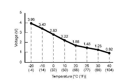
Is the inspection result normal?
YES>>Replace A/C auto amp. Refer to Removal and Installation.
NO>>GO TO 2.
CHECK INTAKE SENSOR POWER SUPPLY
Ignition switch OFF.
Disconnect intake sensor connector.
Ignition switch ON.
Check voltage between intake sensor harness connector and ground.
+ - Voltage
(Approx.)Intake sensor Connector Terminal M145 2 Ground 5 V
Is the inspection result normal?
YES>>GO TO 3.
NO>>GO TO 4.
CHECK INTAKE SENSOR
Check intake sensor. Refer to Component Inspection.
Is the inspection result normal?
YES>>Replace A/C auto amp. Refer to Removal and Installation.
NO>>Replace intake sensor. Refer to Removal and Installation.
CHECK INTAKE SENSOR POWER SUPPLY CIRCUIT FOR SHORT
Ignition switch OFF.
Disconnect A/C auto amp. connector.
Check continuity between intake sensor harness connector and ground.
Intake sensor — Continuity Connector Terminal M145 2 Ground No
Is the inspection result normal?
YES>>Replace A/C auto amp. Refer to Removal and Installation.
NO>>Repair harness or connector.
Component Inspection
CHECK INTAKE SENSOR
Ignition switch OFF.
Replace intake sensor. Refer to Removal and Installation.
Check resistance between intake sensor terminals. Refer to applicable table for the normal value.
Intake sensor Condition Resistance: kΩ Terminals Temperature: °F (°C) 1 2 −4 (−20) 23.60 14 (−10) 13.46 32 (0) 8.00 50 (10) 4.93 68 (20) 3.14 77 (25) 2.54 86 (30) 2.06 104 (40) 1.39
Is the inspection result normal?
YES>>Inspection End.
NO>>Replace intake sensor. Refer to Removal and Installation.
B24a4-15 Intake Sensor Nissan Pathfinder SUV
DTC Description
DTC DETECTION LOGIC
| DTC No. | CONSULT screen terms (Trouble diagnosis content) | DTC detection condition | |
|---|---|---|---|
| B24A4-15 | INTAKE SENSOR (Intake sensor) |
Diagnosis condition | Ignition switch ON |
| Signal (Terminal) | Intake sensor signal | ||
| Threshold | The intake sensor recognition temperature is too low [less than -44°F (-42°C)] | ||
| Diagnosis delay time | 2 second or more | ||
POSSIBLE CAUSE
Intake sensor
A/C auto amp.
Harness or connectors (the sensor circuit is open or shorted to battery)
FAIL-SAFE
—
DTC CONFIRMATION PROCEDURE
PERFORM DTC CONFIRMATION PROCEDURE
 CONSULT
Ignition switch ON.
Select “Self Diagnostic Result” mode of “HVAC”.
Check DTC.
Is DTC detected?
YES>>Refer to DTC Diagnosis Procedure.
NO>>To check malfunction symptom before repair: Refer to Intermittent Incident.
NO>>Confirmation after repair: Inspection End.
DTC Diagnosis Procedure
CHECK INTAKE SENSOR SIGNAL
Ignition switch ON.
Check voltage between A/C auto amp. harness connector.
A/C auto amp. Voltage
(Approx.)Connector Terminals + - M50 23 26 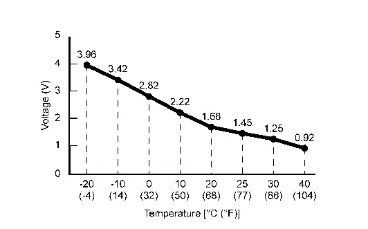
Is the inspection result normal?
YES>>Replace A/C auto amp. Refer to Removal and Installation.
NO>>GO TO 2.
CHECK INTAKE SENSOR POWER SUPPLY
Ignition switch OFF.
Disconnect intake sensor connector.
Ignition switch ON.
Check voltage between intake sensor harness connector and ground.
+ - Voltage
(Approx.)Intake sensor Connector Terminal M145 2 Ground 5 V
Is the inspection result normal?
YES>>GO TO 3.
NO>>GO TO 5.
CHECK INTAKE SENSOR GROUND CIRCUIT FOR OPEN
Ignition switch OFF.
Disconnect A/C auto amp. connector.
Check continuity between intake sensor harness connector and A/C auto amp. harness connector.
Intake sensor A/C auto amp. Continuity Connector Terminal Connector Terminal M145 1 M50 26 Yes
Is the inspection result normal?
YES>>GO TO 4.
NO>>Repair harness or connector.
CHECK INTAKE SENSOR
Check intake sensor. Refer to Component Inspection.
Is the inspection result normal?
YES>>Replace A/C auto amp. Refer to Removal and Installation.
NO>>Replace intake sensor. Refer to Removal and Installation.
CHECK INTAKE SENSOR POWER SUPPLY CIRCUIT FOR OPEN
Ignition switch OFF.
Disconnect A/C auto amp. connector.
Check continuity between intake sensor harness connector and A/C auto amp. harness connector.
Intake sensor A/C auto amp. Continuity Connector Terminal Connector Terminal M145 2 M50 23 Yes
Is the inspection result normal?
YES>>GO TO 6.
NO>>Repair harness or connector.
CHECK INTAKE SENSOR POWER SUPPLY CIRCUIT FOR SHORT
Check voltage between intake sensor harness connector and ground.
| + | - | Voltage (Approx.) | |
|---|---|---|---|
| Intake sensor | |||
| Connector | Terminal | ||
| M145 | 2 | Ground | 0 V |
Is the inspection result normal?
YES>>Replace A/C auto amp. Refer to Removal and Installation.
NO>>Repair harness or connector.
Component Inspection
CHECK INTAKE SENSOR
Ignition switch OFF.
Replace intake sensor. Refer to Removal and Installation.
Check resistance between intake sensor terminals. Refer to applicable table for the normal value.
Intake sensor Condition Resistance: kΩ Terminals Temperature: °F (°C) 1 2 −4 (−20) 23.60 14 (−10) 13.46 32 (0) 8.00 50 (10) 4.93 68 (20) 3.14 77 (25) 2.54 86 (30) 2.06 104 (40) 1.39
Is the inspection result normal?
YES>>Inspection End.
NO>>Replace intake sensor. Refer to Removal and Installation.
B24a6-11 in-Vehicle Sensor Nissan Pathfinder 2026
DTC Description
DTC DETECTION LOGIC
| DTC No. | CONSULT screen terms (Trouble diagnosis content) | DTC detection condition | |
|---|---|---|---|
| B24A6-11 | IN-Nissan Pathfinder Vehicle SENSOR (In-vehicle sensor) |
Diagnosis condition | Ignition switch ON |
| Signal (Terminal) | In-Nissan Pathfinder vehicle sensor signal | ||
| Threshold | The in-Nissan Pathfinder vehicle sensor recognition temperature is too high [more than 212°F (100°C)] | ||
| Diagnosis delay time | 2 second or more | ||
POSSIBLE CAUSE
Front in-vehicle sensor
A/C auto amp.
Harness or connectors (the sensor circuit is shorted to ground)
FAIL-SAFE
In-vehicle temperature is calculated as 77°F (25°C) and air conditioning system is controlled.
DTC CONFIRMATION PROCEDURE
PERFORM DTC CONFIRMATION PROCEDURE
 CONSULT
Ignition switch ON.
Select “Self Diagnostic Result” mode of “HVAC”.
Check DTC.
Is DTC detected?
YES>>Refer to DTC Diagnosis Procedure.
NO>>To check malfunction symptom before repair: Refer to Intermittent Incident.
NO>>Confirmation after repair: Inspection End.
DTC Diagnosis Procedure
CHECK FRONT IN-VEHICLE SENSOR SIGNAL
Ignition switch ON.
Check voltage between A/C auto amp. harness connector.
A/C auto amp. Voltage
(Approx.)Connector Terminals + - M60 48 78 
Is the inspection result normal?
YES>>Replace A/C auto amp. Refer to Removal and Installation.
NO>>GO TO 2.
CHECK FRONT IN-Nissan Pathfinder Vehicle SENSOR POWER SUPPLY
Ignition switch OFF.
Disconnect front in-vehicle sensor connector.
Ignition switch ON.
Check voltage between front in-Nissan Pathfinder vehicle sensor harness connector and ground.
+ - Voltage
(Approx.)Front in-Nissan Pathfinder vehicle sensor Connector Terminal M102 1 Ground 5 V
Is the inspection result normal?
YES>>GO TO 3.
NO>>GO TO 4.
CHECK FRONT IN-Nissan Pathfinder Vehicle SENSOR
Check front in-vehicle sensor. Refer to Component Inspection.
Is the inspection result normal?
YES>>Replace A/C auto amp. Refer to Removal and Installation.
NO>>Replace front in-Nissan Pathfinder vehicle sensor. Refer to Removal and Installation.
CHECK FRONT IN-Nissan Pathfinder Vehicle SENSOR POWER SUPPLY CIRCUIT FOR SHORT
Ignition switch OFF.
Disconnect A/C auto amp. connector.
Check continuity between front in-Nissan Pathfinder vehicle sensor harness connector and ground.
Front in-Nissan Pathfinder vehicle sensor — Continuity Connector Terminal M102 1 Ground No
Is the inspection result normal?
YES>>Replace A/C auto amp. Refer to Removal and Installation.
NO>>Repair harness or connector.
Component Inspection
CHECK FRONT IN-VEHICLE SENSOR
Ignition switch OFF.
Remove front in-Nissan Pathfinder vehicle sensor. Refer to Removal and Installation.
Check resistance between front in-vehicle sensor terminals. Refer to applicable table for the normal value.
Front in-Nissan Pathfinder vehicle sensor Condition Resistance: kΩ Terminals Temperature: °F (°C) 1 2 −4 (−20) 16.50 14 (−10) 9.92 32 (0) 6.19 50 (10) 3.99 68 (20) 2.65 77 (25) 2.19 86 (30) 1.81 104 (40) 1.27
Is the inspection result normal?
YES>>Inspection End.
NO>>Replace front in-Nissan Pathfinder vehicle sensor. Refer to Removal and Installation.