Heater & Air Conditioning Control System - Dtc/circuit Diagnosis
- Power Supply and Ground Circuit
- Sunload Sensor
- Door Motor
- Front Blower Motor
- Rear Blower Motor
- Magnetic Clutch
- Ecv (electrical Control Valve)
- Rear Blower Motor Resistor
- 4020 B20c7-11 A/c Clutch
- 4020 B20c7-15 A/c Clutch
- 4020 B2480-93 Rear Air Mix Door Motor
- 4020 B24a0-49 A/c Auto Amp.
- 4020 B24a1-16 A/c Amp. Power Supply
- 4020 B24a2-55 Configuration Not Implement
- 4020 B24a4-11 Intake Sensor
- 4020 B24a4-15 Intake Sensor
- 4020 B24a6-11 in-Vehicle Sensor
- 4021 B24a6-15 in-Vehicle Sensor
- 4021 B24b4-02 A/c Control Comm
- 4021 B24c6-12 Blower Motor Control
- 4021 B24f5-93 Mode Door Motor
- 4021 U1ca1-08 A/c Switch Assembly Communication
- 4021 U1ca2-08 Door Motor Communication
- 4021 U1caa-02 Mode Door Motor
- 4021 U2140-87 Can Comm Err (ecm)
Power Supply and Ground Circuit Nissan Pathfinder
A/c Auto Amp.
Diagnosis Procedure
CHECK A/C AUTO AMP. GROUND CIRCUIT FOR OPEN
Ignition switch OFF.
Disconnect A/C auto amp. connector.
Check continuity between A/C auto amp. harness connector and ground.
A/C auto amp. — Continuity Connector Terminal M60 58 Ground Yes
Is the inspection result normal?
YES>>GO TO 2.
NO>>Repair harness or connector.
CHECK FUSE
Check that the following fuse is not blown (open):
| Unit | Location | Fuse No. | Capacity |
|---|---|---|---|
| A/C auto amp. | Fuse block (J/B) | 40 | 10 A |
Is the fuse blown (open)?
YES>>Replace the blown fuse after repairing the affected circuit.
NO>>GO TO 3.
CHECK A/C AUTO AMP. POWER SUPPLY
Connect A/C auto amp. connector.
Check voltage between A/C auto amp. harness connector terminals.
A/C auto amp. Condition Voltage
(Approx.)Connector Terminals + − M60 60 58 Ignition switch OFF (auto ACC status) or ON Battery voltage Ignition switch OFF (not auto ACC status) 0 V
Is the inspection result normal?
YES>>Replace A/C auto amp. Refer to Removal and Installation.
NO>>Repair the A/C auto amp. power supply circuit.
Front A/c Switch Assembly
Diagnosis Procedure
CHECK FUSE
Ignition switch OFF.
Check that the following fuse is not blown (open):
Unit Location Fuse No. Capacity Front A/C switch assembly Fuse block (J/B) 40 10 A
Is the fuse blown (open)?
YES>>Replace the blown fuse after repairing the affected circuit.
NO>>GO TO 2.
CHECK FRONT A/C SWITCH ASSEMBLY POWER SUPPLY
Disconnect front A/C switch assembly connector.
Ignition switch ON.
Check voltage between front A/C switch assembly harness connector and ground.
+ − Voltage
(Approx.)Front A/C switch assembly Connector Terminal M69 1 Ground Battery voltage
Is the inspection result normal?
YES>>GO TO 3.
NO>>Repair harness or connector between front A/C switch assembly and fuse.
CHECK FRONT A/C SWITCH ASSEMBLY GROUND CIRCUIT FOR OPEN
Ignition switch OFF.
Check continuity between front A/C switch assembly harness connector and ground.
Front A/C switch assembly — Continuity Connector Terminal M69 6 Ground Yes
Is the inspection result normal?
YES>>Replace front A/C switch assembly. Refer to Removal and Installation.
NO>>Repair harness or connector.
Rear A/c Switch Assembly
Diagnosis Procedure
CHECK FUSE
Ignition switch OFF.
Check that the following fuse is not blown (open):
Unit Location Fuse No. Capacity Rear A/C switch assembly Fuse block (J/B) 40 10 A
Is the fuse blown (open)?
YES>>Replace the blown fuse after repairing the affected circuit.
NO>>GO TO 2.
CHECK REAR A/C SWITCH ASSEMBLY POWER SUPPLY
Disconnect rear A/C switch assembly connector.
Ignition switch ON.
Check voltage between rear A/C switch assembly harness connector and ground.
+ − Voltage
(Approx.)Rear A/C switch assembly Connector Terminal M117 1 Ground Battery voltage
Is the inspection result normal?
YES>>GO TO 3.
NO>>Repair harness or connector between rear air control and fuse.
CHECK REAR A/C SWITCH ASSEMBLY GROUND CIRCUIT FOR OPEN
Ignition switch OFF.
Check continuity between rear A/C switch assembly harness connector and ground.
Rear A/C switch assembly — Continuity Connector Terminal M117 6 Ground Yes
Is the inspection result normal?
YES>>Replace rear A/C switch assembly. Refer to Removal and Installation.
NO>>Repair harness or connector.
Sunload Sensor Nissan Pathfinder Fifth generation
Diagnosis Procedure
CHECK SUNLOAD SENSOR SIGNAL
Ignition switch ON.
Check voltage between A/C auto amp. harness connector.
A/C auto amp. Voltage
(Approx.)Connector Terminals + − M60 47 78 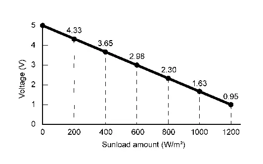
63
Is the inspection result normal?
YES>>Inspection End.
NO>>GO TO 2.
CHECK SUNLOAD SENSOR POWER SUPPLY
Ignition switch OFF.
Disconnect sunload sensor connector.
Ignition switch ON.
Check voltage between sunload sensor harness connector and ground.
+ − Voltage
(Approx.)Sunload sensor Connector Terminal M278 1 Ground 5 V 2
Is the inspection result normal?
YES>>GO TO 3.
NO>>GO TO 5.
CHECK SUNLOAD SENSOR GROUND CIRCUIT FOR OPEN
Ignition switch OFF.
Disconnect A/C auto amp. connector.
Check continuity between sunload sensor harness connector and A/C auto amp. harness connector.
Sunload sensor A/C auto amp. Continuity Connector Terminal Connector Terminal M278 3 M60 78 Yes
Is the inspection result normal?
YES>>GO TO 4.
NO>>Repair harness or connector.
REPLACE SUNLOAD SENSOR
Replace sunload sensor. Refer to Removal and Installation.
Is the inspection result normal?
YES>>Inspection End.
NO>>Replace A/C auto amp. Refer to Removal and Installation.
CHECK SUNLOAD SENSOR POWER SUPPLY CIRCUIT FOR OPEN
Ignition switch OFF.
Disconnect A/C auto amp. connector.
Check continuity between sunload sensor harness connector and A/C auto amp. harness connector.
Sunload sensor A/C auto amp. Continuity Connector Terminal Connector Terminal M278 1 M60 63 Yes 2 47
Is the inspection result normal?
YES>>GO TO 6.
NO>>Repair harness or connector.
CHECK SUNLOAD SENSOR POWER SUPPLY CIRCUIT FOR SHORT
Check continuity between sunload sensor harness connector and ground.
| Sunload sensor | — | Continuity | |
|---|---|---|---|
| Connector | Terminal | ||
| M278 | 1 | Ground | No |
| 2 | |||
Is the inspection result normal?
YES>>GO TO 4.
NO>>Repair harness or connector.
Door Motor Nissan Pathfinder
Diagnosis Procedure
CHECK DOOR MOTOR POWER SUPPLY
Ignition switch ON.
Check voltage between intake door motor harness connector and A/C auto amp. harness connector.
| + | − | Voltage (Approx.) | ||
|---|---|---|---|---|
| Intake door motor | A/C auto amp. | |||
| Connector | Terminal | Connector | Terminal | |
| M128 | 1 | M60 | 58 | Battery voltage |
Is the inspection result normal?
YES>>GO TO 2.
NO>>GO TO 6.
CHECK DOOR MOTOR GROUND CIRCUIT FOR OPEN
Ignition switch OFF.
Disconnect intake door motor connector and A/C auto amp. connector.
Check continuity between intake door motor harness connector and A/C auto amp. harness connector.
Intake door motor A/C auto amp. Continuity Connector Terminal Connector Terminal M128 2 M50 27 Yes
Is the inspection result normal?
YES>>GO TO 3.
NO>>Repair harness or connector.
CHECK DOOR MOTOR LIN SIGNAL
Connect intake door motor connector and A/C auto amp. connector.
Ignition switch ON.
Confirm output waveform between intake door motor harness connector and A/C auto amp. harness connector with oscilloscope.
+ − Output waveform Intake door motor A/C auto amp. Connector Terminal Connector Terminal M128 3 M60 58 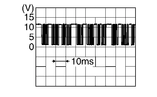
Is the inspection result normal?
YES>>Inspection End.
NO>>GO TO 4.
CHECK DOOR MOTOR LIN SIGNAL CIRCUIT FOR OPEN
Ignition switch OFF.
Disconnect A/C auto amp. and intake door motor connector.
Check continuity between intake door motor harness connector and A/C auto amp. harness connector.
Intake door motor A/C auto amp. Continuity Connector Terminal Connector Terminal M128 3 M50 2 Yes
Is the inspection result normal?
YES>>GO TO 5.
NO>>Repair harness or connector.
CHECK DOOR MOTOR LIN SIGNAL CIRCUIT FOR SHORT
Ignition switch OFF.
Disconnect following connectors:
Air mix door motor LH
Air mix door motor RH
Air mix door motor (rear)
Mode door motor (front)
Mode door motor (rear)
Check continuity between A/C auto amp. harness connector and ground.
A/C auto amp. — Continuity Connector Terminal M50 2 Ground No
Is the inspection result normal?
YES>>Replace A/C auto amp. Refer to Removal and Installation.
NO>>Repair harness or connector.
CHECK DOOR MOTOR POWER SUPPLY CIRCUIT FOR OPEN
Ignition switch OFF.
Disconnect intake door motor and A/C auto amp. connector.
Check continuity between intake door motor harness connector and A/C auto amp. harness connector.
Intake door motor A/C auto amp. Continuity Connector Terminal Connector Terminal M128 1 M50 1 Yes
Is the inspection result normal?
YES>>GO TO 7.
NO>>Repair harness or connector.
CHECK DOOR MOTOR POWER SUPPLY CIRCUIT FOR SHORT
Disconnect following connectors:
Air mix door motor LH
Air mix door motor RH
Air mix door motor (rear)
Mode door motor (front)
Mode door motor (rear)
Check continuity between A/C auto amp. harness connector and ground.
A/C auto amp. — Continuity Connector Terminal M50 1 Ground No
Is the inspection result normal?
YES>>Replace A/C auto amp. Refer to Removal and Installation.
NO>>Repair harness or connector.
Front Blower Motor Nissan Pathfinder Fifth generation
Diagnosis Procedure
CHECK FUSIBLE LINK
Ignition switch OFF.
Check that the following fusible link is not blown (open):
Unit Location Fusible link No. Capacity Front blower motor Fuse block (J/B) FF 40 A
Is the fusible link blown (open)?
YES>>Replace the blown fuse after repairing the affected circuit.
NO>>GO TO 2.
CHECK FRONT BLOWER MOTOR POWER SUPPLY
Disconnect the front blower motor connector.
Ignition switch ON.
Check voltage between front blower motor harness connector and ground.
+ − Voltage
(Approx.)Front blower motor Connector Terminal M187 1 Ground Battery voltage
Is the inspection result normal?
YES>>GO TO 4.
NO>>GO TO 3.
CHECK FRONT BLOWER MOTOR POWER SUPPLY CIRCUIT FOR OPEN
Ignition switch OFF.
Disconnect fuse block (J/B) harness connector.
Check continuity between fuse block (J/B) harness connector and front blower motor harness connector.
Fuse block (J/B) Front blower motor Continuity Connector Terminal Connector Terminal M3 1A M187 1 Yes
Is the inspection result normal?
YES>>Repair the front blower motor power supply circuit.
NO>>Repair the harnesses or connectors.
CHECK FRONT BLOWER MOTOR GROUND CIRCUIT FOR OPEN
Ignition switch OFF.
Check continuity between front blower motor harness connector and ground.
Front blower motor — Continuity Connector Terminal M187 3 Ground Yes
Is the inspection result normal?
YES>>GO TO 5.
NO>>Repair the harnesses or connectors.
CHECK FRONT BLOWER MOTOR CONTROL SIGNAL
Connect front blower motor connector.
Ignition switch ON.
Check duty ratios between front blower motor harness connector and ground by using an oscilloscope.
+ − Condition Output waveform
(Approx.)Front blower motor Connector Terminal M187 2 Ground Front blower motor: OFF Battery voltage Front blower motor: 1st speed (manual) 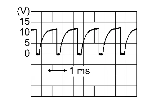
Front blower motor: 7th speed (manual) 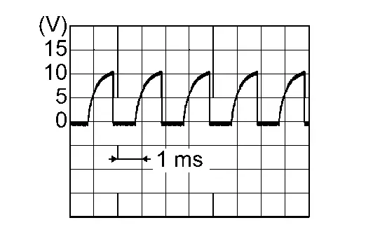
Is the inspection result normal?
YES>>Replace front blower motor. Refer to Removal and Installation.
NO>>GO TO 6.
CHECK FRONT BLOWER MOTOR CONTROL SIGNAL CIRCUIT FOR OPEN
Ignition switch OFF.
Disconnect front blower motor connector and A/C auto amp. connector.
Check continuity between front blower motor harness connector and A/C auto amp. harness connector.
Front blower motor A/C auto amp. Continuity Connector Terminal Connector Terminal M187 2 M50 34 Yes
Is the inspection result normal?
YES>>GO TO 7.
NO>>Repair the harnesses or connectors.
REPLACE FRONT BLOWER MOTOR
Replace front blower motor. Refer to Removal and Installation.
Ignition switch ON.
Change fan speed from 1st – 7th, and check that front blower motor operates normally.
Is the inspection result normal?
YES>>Inspection End.
NO>>Replace the A/C auto amp. Refer to Removal and Installation.
Component Inspection (Front Blower Motor)
CHECK FRONT BLOWER MOTOR-I
Replace front blower motor. Refer to Removal and Installation.
Check that there is not any mixing foreign object in the front blower motor.
Is the inspection result normal?
YES>>GO TO 2.
NO>>Replace front blower motor. Refer to Removal and Installation.
CHECK FRONT BLOWER MOTOR-II
Check that there is not breakage or damage in the front blower motor.
Is the inspection result normal?
YES>>GO TO 3.
NO>>Replace front blower motor. Refer to Removal and Installation.
CHECK FRONT BLOWER MOTOR-III
Check that front blower motor turns smoothly.
Is the inspection result normal?
YES>>Inspection End.
NO>>Replace front blower motor. Refer to Removal and Installation.
Rear Blower Motor Nissan Pathfinder Fifth generation
Diagnosis Procedure
CHECK REAR BLOWER MOTOR POWER SUPPLY
Disconnect the rear blower motor connector.
Ignition switch ON.
Check voltage between rear blower motor harness connector and ground.
+ − Voltage
(Approx.)Rear blower motor Connector Terminal B126 1 Ground Battery voltage
Is the inspection result normal?
YES>>GO TO 3.
NO>>GO TO 2.
CHECK REAR BLOWER MOTOR POWER SUPPLY CIRCUIT FOR OPEN
Ignition switch OFF.
Disconnect rear blower motor resistor connector.
Check continuity between rear blower motor resistor harness connector and rear blower motor harness connector.
Rear blower motor resistor Rear blower motor Continuity Connector Terminal Connector Terminal B134 1 B126 1 Yes
Is the inspection result normal?
YES>>Repair the rear blower motor power supply circuit.
NO>>Repair the harnesses or connectors.
CHECK REAR BLOWER MOTOR GROUND CIRCUIT FOR OPEN
Ignition switch OFF.
Check continuity between rear blower motor harness connector and ground.
Rear blower motor — Continuity Connector Terminal B126 2 Ground Yes
Is the inspection result normal?
YES>>GO TO 4.
NO>>Repair the harnesses or connectors.
REPLACE REAR BLOWER MOTOR
Replace rear blower motor. Refer to Removal and Installation.
Ignition switch ON.
Change fan speed from 1st – 7th, and check that rear blower motor operates normally.
Is the inspection result normal?
YES>>Inspection End.
NO>>Replace the rear blower motor resistor. Refer to Removal and Installation.
Component Inspection (Rear Blower Motor)
CHECK REAR BLOWER MOTOR-I
Replace rear blower motor. Refer to Removal and Installation.
Check that there is not any mixing foreign object in the rear blower motor.
Is the inspection result normal?
YES>>GO TO 2.
NO>>Replace rear blower motor. Refer to Removal and Installation.
CHECK REAR BLOWER MOTOR-II
Check that there is not breakage or damage in the rear blower motor.
Is the inspection result normal?
YES>>GO TO 3.
NO>>Replace rear blower motor. Refer to Removal and Installation.
CHECK REAR BLOWER MOTOR-III
Check that rear blower motor turns smoothly.
Is the inspection result normal?
YES>>Inspection End.
NO>>Replace rear blower motor. Refer to Removal and Installation.
Magnetic Clutch Nissan Pathfinder Fifth generation
Component Function Check
CHECK MAGNETIC CLUTCH OPERATION
 CONSULT
Select “HVAC TEST” in “Active Test” mode of “HVAC”.
Select “MODE 1”.
With operating the test item, check magnetic clutch operation by listening and viewing.
Does it operate normally?
YES>>Inspection End.
NO>>Refer to Diagnosis Procedure.
Diagnosis Procedure
CHECK MAGNETIC CLUTCH
 CONSULT
Ignition switch ON.
Select “HVAC TEST” in “Active Test” mode of “HVAC”.
With operating the test item, check voltage between IPDM E/R harness connector and ground.
+ − Condition Voltage
(Approx.)IPDM E/R Connector Terminal F24 65 Ground Active test: HVAC TEST Off 0 V MODE 1 Battery voltage
Is the inspection result normal?
YES>>GO TO 2.
NO>>Replace IPDM E/R. Refer to Removal and Installation.
CHECK MAGNETIC CLUTCH POWER SUPPLY CIRCUIT FOR OPEN
Ignition switch OFF.
Disconnect IPDM E/R connector and A/C compressor connector.
Check continuity between IPDM E/R harness connector and A/C compressor harness connector.
IPDM E/R A/C compressor Continuity Connector Terminal Connector Terminal F24 65 F3 1 Yes
Is the inspection result normal?
YES>>GO TO 3.
NO>>Repair harness or connector.
CHECK MAGNETIC CLUTCH GROUND CIRCUIT FOR OPEN
Check continuity between A/C compressor harness connector and ground.
| A/C compressor | — | Continuity | |
|---|---|---|---|
| Connector | Terminal | ||
| F3 | 2 | Ground | Yes |
Is the inspection result normal?
YES>>Replace A/C compressor. Refer to Removal and Installation.
NO>>Repair harness or connector.
Ecv (electrical Control Valve) Nissan Pathfinder 2026
Diagnosis Procedure
CHECK FUSE
Ignition switch OFF.
Check that the following fuse is not blown (open):
Unit Location Fuse No. Capacity A/C compressor IPDM E/R 71 10 A
Is the fuse blown (open)?
YES>>Replace the blown fuse after repairing the affected circuit.
NO>>GO TO 2.
CHECK ECV POWER SUPPLY CIRCUIT
Disconnect A/C compressor connector.
Ignition switch ON.
Check voltage between A/C compressor harness connector and ground.
+ − Voltage
(Approx.)A/C compressor Connector Terminal F4 3 Ground Battery voltage
Is the inspection result normal?
YES>>GO TO 4.
NO>>GO TO 3.
CHECK ECV POWER SUPPLY CIRCUIT FOR OPEN
Ignition switch OFF.
Disconnect IPDM E/R connector.
Check continuity between A/C compressor harness connector and IPDM E/R harness connector.
A/C compressor IPDM E/R Continuity Connector Terminal Connector Terminal F4 3 F24 71 Yes
Is the inspection result normal?
YES>>Replace IPDM E/R. Refer to Removal and Installation.
NO>>Repair harness or connector.
CHECK ECV CONTROL SIGNAL CIRCUIT FOR OPEN
Ignition switch OFF.
Disconnect IPDM E/R connector.
Check continuity between A/C compressor harness connector and IPDM E/R harness connector.
A/C compressor IPDM E/R Continuity Connector Terminal Connector Terminal F4 4 E78 98 Yes
Is the inspection result normal?
YES>>GO TO 5.
NO>>Repair harness or connector.
CHECK ECV
Check ECV. Refer to Component Inspection.
Is the inspection result normal?
YES>>Replace IPDM E/R. Refer to Removal and Installation.
NO>>Replace A/C compressor. Refer to Removal and Installation.
Component Inspection
CHECK ECV
Ignition switch OFF.
Check continuity between A/C compressor terminals.
| A/C compressor | Continuity | |
|---|---|---|
| Terminals | ||
| 3 | 4 | Yes |
Is the inspection result normal?
YES>>Inspection End.
NO>>Replace A/C compressor. Refer to Removal and Installation.
Rear Blower Motor Resistor Nissan Pathfinder 5th Gen
Diagnosis Procedure
CHECK REAR BLOWER MOTOR RESISTOR POWER SUPPLY CIRCUIT
Ignition switch OFF.
Disconnect rear blower motor resistor connector.
Ignition switch ON.
Check voltage between rear blower motor resistor harness connector and ground.
+ — Voltage
(Approx.)Rear blower motor resistor Connector Terminal B133 6 Ground Battery voltage
Is the inspection result normal?
YES>>GO TO 2.
NO>>GO TO 5.
CHECK REAR BLOWER MOTOR RESISTOR GROUND CIRCUIT
Ignition switch OFF.
Check continuity between rear blower motor resistor harness connector and ground.
Rear blower motor resistor — Continuity Connector Terminal B133 4 Ground Yes
Is the inspection result normal?
YES>>GO TO 3.
NO>>Repair harness or connector.
CHECK REAR BLOWER MOTOR RESISTOR SIGNAL CIRCUIT FOR OPEN
Disconnect A/C auto amp. connector.
Check continuity between rear blower motor resistor harness connector and A/C auto amp. harness connector.
Rear blower motor resistor A/C auto amp. Continuity Connector Terminal Connector Terminal B133 5 M60 74 Yes
Is the inspection result normal?
YES>>GO TO 4.
NO>>Repair harness or connector.
CHECK REAR BLOWER MOTOR RESISTOR SIGNAL CIRCUIT FOR SHORT
Check continuity between rear blower motor resistor harness connector and ground.
| Rear blower motor resistor | — | Continuity | |
|---|---|---|---|
| Connector | Terminal | ||
| B133 | 5 | Ground | No |
Is the inspection result normal?
YES>>Replace rear blower motor resistor. Refer to Removal and Installation.
NO>>Repair harness or connector.
CHECK REAR BLOWER MOTOR RESISTOR POWER SUPPLY CIRCUIT FOR OPEN
Ignition switch OFF.
Disconnect fuse block(J/B) connector.
Check continuity between rear blower motor resistor harness connector and fuse block(J/B) harness connector.
Rear blower motor resistor Fuse block(J/B) Continuity Connector Terminal Connector Terminal B133 6 B34 7M No
Is the inspection result normal?
YES>>Check the 20A fuse [No. 64, located in fuse block (J/B)].
NO>>Repair harness or connector.