Body Repair - Service Information

In this manual: Body Repair - Service Information
General Information — 8Engine :: Engine Mechanical — 19Engine Lubrication System - Precautions. Preparation — 1Engine Lubrication System - Lubrication System (System Description). Engine Oil Pressure (Basic Inspection). Service Data and Specifications (SDS) — 1Engine Cooling System - Precautions. Preparation. Service Data and Specifications (SDS) — 1Engine Cooling System - Engine Coolant — 1Engine Control System - System Description — 1System Description - Component Parts ++ — 1System Description - System ++ — 1Engine Control System - Ecu Diagnosis Information — 1Ecu Diagnosis Information - Ecm ++ — 1Engine Control System - Basic Inspection — 1Basic Inspection - Diagnosis and Repair Workflow ++ — 1Basic Inspection - Basic Inspection ++ — 1Basic Inspection - Additional Service When Replacing Ecm ++ — 1Basic Inspection - Fuel Pressure Check ++ — 1Basic Inspection - How to Set Srt Code ++ — 1Basic Inspection - How to Erase Permanent Dtc ++ — 1Engine Control System - Dtc/circuit Diagnosis — 1Engine Control System - Symptom Diagnosis — 1Engine Control System - Periodic Maintenance — 1Engine Control System - Removal and Installation — 1Fuel System - Precautions. Preparation. Service Data and Specifications (SDS) — 1Fuel System - Fuel System (Periodic Maintenance). Fuel Level Sensor Unit (Disassembly and Assembly) — 1Exhaust System - Precautions. Preparation — 1Exhaust System - Exhaust System (Periodic Maintenance). Exhaust System (Removal and Installation) — 1Starting System - Precautions. Preparation. Starter Motor (Service Data and Specifications (sds)) — 1Starting System - Diagnosis and Repair Work Flow — 1Starting System - Starting System (Symptom Diagnosis). Starter Motor (Removal and Installation) — 1Accelerator Control System - Precautions. Service Data and Specifications (SDS) — 1Accelerator Control System - Accelerator Pedal Assembly — 1Transmission & Driveline :: Transaxle & Transmission — 21Driveline - System Description — 1Transfer: Ty92b - Ecu Diagnosis Information. Awd Control Unit ++ — 1Driveline - Basic Inspection — 1Driveline - Dtc/circuit Diagnosis — 1Driveline - Symptom Diagnosis — 1Driveline - Removal and Installation — 1Transfer: Ty92b - Unit Removal and Installation. Transfer Assembly ++ — 1Driveline - Unit Disassembly and Assembly — 1Driveline - Basic Inspection — 1Driveline - Removal and Installation — 1Driveline - Unit Disassembly and Assembly — 1Front Axle - Precautions. Preparation — 1Front Axle - Noise, Vibration and Harshness (nvh) Troubleshooting (Symptom Diagnosis). Service Data and Specifications (SDS) — 1Front Axle - Front Drive Shaft Boot — 1Front Axle - Front Drive Shaft — 1Rear Axle - Precautions. Preparation. Service Data and Specifications (SDS) — 1Rear Axle - Noise, Vibration and Harshness (nvh) Troubleshooting — 1Rear Axle - Rear Drive Shaft — 1Suspension :: Front Suspension — 7Rear Suspension - Precautions. Preparation — 1Rear Suspension - Noise, Vibration and Harshness (nvh) Troubleshooting (Symptom Diagnosis). Service Data and Specifications (SDS) — 1Rear Suspension - Rear Suspension Assembly — 1Road Wheels & Tires - Precautions — 1Road Wheels & Tires - Preparation. Bcm (Ecu Diagnosis Information). Service Data and Specifications (SDS) — 1Road Wheels & Tires - System — 1Brakes :: Brake System — 9Parking Brake System - Precautions. Preparation — 1Parking Brake System - System — 1Vdc/tcs/abs - Precautions ++ — 1Brake Control System - System Description — 1System Description - Component Parts ++ — 1System Description - System ++ — 1Brake Control System - Basic Inspection — 1Brake Control System - Symptom Diagnosis — 1Brake Control System - Removal and Installation — 1Brake Control System - System Description — 1Brake Control System - Dtc/circuit Diagnosis — 1Brake Control System - Removal and Installation — 1Brake Control System - System Description — 1Brake Control System - Basic Inspection — 1Brake Control System - Symptom Diagnosis — 1Brake Control System - System Description — 1Brake Control System - Basic Inspection — 1Brake Control System - Symptom Diagnosis — 1Steering :: Steering System — 9Steering Control System - Precautions — 1Steering Control System - System — 1Steering Control System - Eps Control Unit (Ecu Diagnosis Information. Removal and Installation) — 1Restraints :: Seat Belt — 7Srs Air Bag - Precautions. Preparation — 1Srs Air Bag - Collision Diagnosis — 1Srs Air Bag - Occupant Classification System — 1Srs Air Bag Control System - Precautions — 1Srs Air Bag Control System - System — 1Srs Air Bag Control System - Diagnosis Sensor Unit — 1Srs Air Bag Control System - Inspection and Adjustment — 1Ventilation, Heater & Air Conditioner :: Ventilation System — 6Heater & Air Conditioning System - Precautions — 1Heater & Air Conditioning System - Preparation — 1Heater & Air Conditioning System - Component Parts — 1Heater & Air Conditioning System - Diagnosis and Repair Work Flow — 1Heater & Air Conditioning System - Compressor — 1Heater & Air Conditioning System - Cooler Pipe and Hose — 1Heater & Air Conditioning System - Condenser. Condenser — 1Heater & Air Conditioning System - Heating and Cooling Unit Assembly — 1Heater & Air Conditioning System - Service Data and Specifications (SDS) — 1Heater & Air Conditioning Control System - System Description — 1System Description - Component Parts ++ — 1System Description - System ++ — 1System Description - Operation ++ — 1Heater & Air Conditioning Control System - Ecu Diagnosis Information — 1Heater & Air Conditioning Control System - Basic Inspection — 1Heater & Air Conditioning Control System - Dtc/circuit Diagnosis — 1Heater & Air Conditioning Control System - Symptom Diagnosis — 1Heater & Air Conditioning Control System - Removal and Installation — 1Body Interior :: Interior — 8Instrument Panel - Precautions. Preparation. Clip List — 1Instrument Panel - Squeak and Rattle Trouble Diagnoses — 1Instrument Panel - Cluster Lid C — 1Seat - Precautions — 1Seat - Preparation. Clip List — 1Seat - Component Parts — 1Seat - System — 1Seat - Diagnosis and Repair Work Flow — 1Seat - Front Seat — 1Seat - Second Row Seats — 1Seat - Third Row Seats — 1Seat - Front Seat — 1Seat - Second Row Seat — 1Seat - Third Row Seat — 1Automatic Drive Positioner - Precautions. Preparation — 1Automatic Drive Positioner - System — 1Automatic Drive Positioner - Diagnosis and Repair Work Flow — 1Automatic Drive Positioner - Inspection and Adjustment — 1Body Exterior, Doors, Roof & Vehicle Security :: Door & Lock — 38Security Control System - Precautions — 1Security Control System - System — 1Security Control System - Ecm, Bcm, Intelligent Key Unit, Ipdm E/r — 1Security Control System - Vehicle Security System Cannot Be Set — 1Glass & Window System - Precautions. Preparation — 1Glass & Window System - Squeak and Rattle Trouble Diagnoses — 1Power Window Control System - Precautions. Preparation — 1Power Window Control System - Power Supply and Ground Circuit — 1Power Window Control System - Power Window Motor Circuit — 1Power Window Control System - Front Power Window Rh Alone Does Not Operate — 1Power Window Control System - Rear Lh Side Power Window Alone Does Not Operate — 1Power Window Control System - Rear Rh Side Power Window Alone Does Not Operate — 1Roof - Precautions. Preparation — 1Roof - Power Supply and Ground Circuit — 1Roof - Moonroof Switch Assembly — 1Roof - Lin Communication Circuit — 1Roof - Auto Operation Does Not Operate — 1Roof - Anti-Pinch Function Does Not Operate — 1Exterior - Precautions. Preparation. Clip List (Preparation) — 1Exterior - Squeak and Rattle Trouble Diagnoses — 1Exterior - Fender Protector — 1Exterior - Over Fender — 1Exterior - Under Cover — 1Exterior - Roof Side Rail — 1Body Repair - Service Information — 1Service Information - Sheet Metal Work ++ — 1Service Information - Body Welding and Precautions ++ — 1Service Information - Safety and Health ++ — 1Service Information - Repairing Procedures and Precautions ++ — 1Body Repair - Precaution — 1Body Repair - Preparation — 1Body Repair - Removal and Installation — 1Driver Controls :: Mirrors — 8Exterior Lighting System - System Description — 1System Description - Component Parts ++ — 1Exterior Lighting System - Basic Inspection — 1Exterior Lighting System - Dtc/circuit Diagnosis — 1Exterior Lighting System - Symptom Diagnosis — 1Exterior Lighting System - Periodic Maintenance — 1Exterior Lighting System - Removal and Installation — 1Interior Lighting System - Precautions. Preparation — 1Interior Lighting System - Component Parts. Interior Lighting System — 1Interior Lighting System - System — 1Interior Lighting System - Diagnosis and Repair Work Flow — 1Interior Lighting System - Interior Lighting System Symptoms (Symptom Diagnosis). Bcm (Ecu Diagnosis Information). Service Data and Specifications (SDS) — 1Interior Lighting System - Foot Lamp — 1Wiper & Washer - Precautions — 1Wiper & Washer - Preparation. Bcm, Ipdm E/r (Ecu Diagnosis Information). Service Data and Specifications (SDS) — 1Wiper & Washer - System — 1Wiper & Washer - Diagnosis and Repair Work Flow — 1Defogger - Precautions. Bcm, A/c Auto Amp. (Ecu Diagnosis Information) — 1Defogger - Diagnosis and Repair Work Flow — 1Horn - Precautions — 1Electrical & Power Control :: Power Outlet — 13Body Control System - Precautions. Preparation — 1Body Control System - Component Parts — 1Body Control System - System — 1Body Control System - Diagnosis System (bcm) — 1Body Control System - Bcm — 1Lan System - System Description — 1Lan System - System Description — 1Lan System - Dtc/circuit Diagnosis — 1Lan System - System Description — 1Lan System - Dtc/circuit Diagnosis — 1Power Control System - System Description — 1Power Control System - Basic Inspection — 1Power Control System - Dtc/circuit Diagnosis — 1Power Control System - System Description — 1Power Control System - Basic Inspection — 1Power Control System - Dtc/circuit Diagnosis — 1Power Control System - Removal and Installation — 1Charging System - Precautions. Preparation. Ecm, Ipdm E/r (Ecu Diagnosis Information) — 1Charging System - Diagnosis and Repair Work Flow — 1Charging System - Charging System (Symptom Diagnosis). Generator (Removal and Installation). Service Data and Specifications (SDS) — 1Power Supply, Ground & Circuit Elements - Precautions. Preparation. Service Data and Specifications (SDS) — 1Driver Information & Multimedia :: Meter, Warning Lamp & Indicator — 25Warning Chime System - Application Notice (How to Use This Manual). Precautions — 1Warning Chime System - System — 1Warning Chime System - Diagnosis System (combination Meter) — 1Warning Chime System - Bcm, Combination Meter (Ecu Diagnosis Information). Diagnosis and Repair Work Flow (Basic Inspection) — 1Sonar System - Precautions. Preparation — 1Sonar System - Sonar Control Unit — 1Dtc/circuit Diagnosis - B2720 Corner Sensor [rl] ++ — 1Audio, Visual & Navigation System - System Description — 1System Description - Component Parts ++ — 1System Description - System ++ — 1Audio, Visual & Navigation System - Ecu Diagnosis Information — 1Audio, Visual & Navigation System - Basic Inspection — 1Audio, Visual & Navigation System - Dtc/circuit Diagnosis — 1Dtc/circuit Diagnosis - Multi Av (av Control Unit) ++ — 1Audio, Visual & Navigation System - Symptom Diagnosis — 1Symptom Diagnosis - Multi Av System ++ — 1Audio, Visual & Navigation System - Removal and Installation — 1Audio, Visual & Navigation System - System Description — 1Audio, Visual & Navigation System - Ecu Diagnosis Information — 1Audio, Visual & Navigation System - Basic Inspection — 1Audio, Visual & Navigation System - Dtc/circuit Diagnosis — 1Audio, Visual & Navigation System - Symptom Diagnosis — 1Audio, Visual & Navigation System - Removal and Installation — 1Audio, Visual & Navigation System - System Description — 1Audio, Visual & Navigation System - Basic Inspection — 1Audio, Visual & Navigation System - Dtc/circuit Diagnosis — 1Audio, Visual & Navigation System - Symptom Diagnosis — 1Audio, Visual & Navigation System - Removal and Installation — 1Audio, Visual & Navigation System - System Description — 1Audio, Visual & Navigation System - Basic Inspection — 1Audio, Visual & Navigation System - Dtc/circuit Diagnosis — 1Audio, Visual & Navigation System - Symptom Diagnosis — 1Audio, Visual & Navigation System - Removal and Installation — 1Cruise Control & Driver Assistance :: Cruise Control System — 17Driver Assistance System - System Description — 1Driver Assistance System - Basic Inspection — 1Driver Assistance System - Dtc/circuit Diagnosis — 1Driver Assistance System - System Description — 1System Description - Component Parts ++ — 1System Description - System ++ — 1System Description - Operation ++ — 1System Description - Handling Precaution ++ — 1Driver Assistance System - Ecu Diagnosis Information — 1Driver Assistance System - Basic Inspection — 1Basic Inspection - Distance Sensor Alignment ++ — 1Basic Inspection - Camera Aiming Adjustment ++ — 1Basic Inspection - Action Test ++ — 1Driver Assistance System - Dtc/circuit Diagnosis — 1Dtc/circuit Diagnosis - Laser/radar (distance Sensor) ++ — 1Dtc/circuit Diagnosis - Lane Camera (front Camera Unit) ++ — 1Driver Assistance System - Symptom Diagnosis — 1Driver Assistance System - Removal and Installation — 1Driver Assistance System - System Description — 1System Description - System ++ — 1Driver Assistance System - Basic Inspection — 1Driver Assistance System - Dtc/circuit Diagnosis — 1Drive Mode System - Precautions — 1Drive Mode System - Component Parts. Drive Mode System — 1Drive Mode System - System — 1Drive Mode System - Diagnosis and Repair Work Flow — 1Drive Mode System - Drive Mode Select Switch Circuit — 1Maintenance - Precautions. Preparation — 1Maintenance - General Maintenance — 1Maintenance - Periodic Maintenance — 1Maintenance - Recommended Fluids and Lubricants — 1Maintenance - Engine Maintenance — 1Maintenance - Chassis and Body Maintenance — 1Engine Lubrication System - Periodic Maintenance — 1Engine Lubrication System - Removal and Installation — 1Engine Cooling System - System Description — 1Engine Cooling System - Removal and Installation — 1Engine Control System - Vq35dd — 1Fuel System - Removal and Installation — 1Starting System - System Description — 1Starting System - Dtc/circuit Diagnosis — 1Driveline - Transfer: Ty92b — 1Driveline - Rear Propeller Shaft: 3fcj-Cvj — 1Driveline - Rear Final Drive: R145 — 1Front Axle - Periodic Maintenance — 1Front Axle - Removal and Installation — 1Rear Axle - Periodic Maintenance — 1Rear Axle - Removal and Installation — 1Rear Suspension - Removal and Installation — 1Road Wheels & Tires - System Description — 1Road Wheels & Tires - Basic Inspection — 1Road Wheels & Tires - Dtc/circuit Diagnosis — 1Road Wheels & Tires - Symptom Diagnosis — 1Road Wheels & Tires - Periodic Maintenance — 1Road Wheels & Tires - Removal and Installation — 1Parking Brake System - System Description — 1Parking Brake System - Basic Inspection — 1Parking Brake System - Dtc/circuit Diagnosis — 1Parking Brake System - Symptom Diagnosis — 1Parking Brake System - Removal and Installation — 1Brake Control System - Vdc/tcs/abs — 1Brake Control System - Automatic Brake Hold — 1Brake Control System - Automatic Emergency Braking — 1Brake Control System - Rear Automatic Braking — 1Steering Control System - System Description — 1Steering Control System - Basic Inspection — 1Steering Control System - Dtc/circuit Diagnosis — 1Steering Control System - Symptom Diagnosis — 1Srs Air Bag - Removal and Installation — 1Srs Air Bag Control System - System Description — 1Srs Air Bag Control System - Basic Inspection — 1Srs Air Bag Control System - Symptom Diagnosis — 1Heater & Air Conditioning System - Symptom Diagnosis — 1Heater & Air Conditioning System - Periodic Maintenance — 1Heater & Air Conditioning Control System - Automatic Air Conditioning — 1Instrument Panel - Removal and Installation — 1Instrument Panel - Unit Disassembly and Assembly — 1Seat - Ecu Diagnosis Information — 1Seat - Dtc/circuit Diagnosis — 1Seat - Symptom Diagnosis — 1Automatic Drive Positioner - System Description — 1Automatic Drive Positioner - Ecu Diagnosis Information — 1Automatic Drive Positioner - Dtc/circuit Diagnosis — 1Automatic Drive Positioner - Symptom Diagnosis — 1Automatic Drive Positioner - Removal and Installation — 1Security Control System - System Description — 1Security Control System - Basic Inspection — 1Security Control System - Dtc/circuit Diagnosis — 1Security Control System - Symptom Diagnosis — 1Security Control System - Removal and Installation — 1Glass & Window System - Removal and Installation — 1Power Window Control System - System Description — 1Power Window Control System - Ecu Diagnosis Information — 1Power Window Control System - Basic Inspection — 1Power Window Control System - Dtc/circuit Diagnosis — 1Power Window Control System - Symptom Diagnosis — 1Power Window Control System - Removal and Installation — 1Roof - System Description — 1Roof - Ecu Diagnosis Information — 1Roof - Basic Inspection — 1Roof - Dtc/circuit Diagnosis — 1Roof - Symptom Diagnosis — 1Roof - Removal and Installation — 1Exterior - System Description — 1Exterior - Removal and Installation — 1Body Repair - Repair Information — 1Exterior Lighting System - Led Headlamp — 1Interior Lighting System - Dtc/circuit Diagnosis — 1Interior Lighting System - Removal and Installation — 1Wiper & Washer - System Description — 1Wiper & Washer - Dtc/circuit Diagnosis — 1Wiper & Washer - Symptom Diagnosis — 1Wiper & Washer - Removal and Installation — 1Defogger - System Description — 1Defogger - Dtc/circuit Diagnosis — 1Defogger - Symptom Diagnosis — 1Defogger - Removal and Installation — 1Horn - Removal and Installation — 1Body Control System - Basic Inspection — 1Body Control System - Dtc/circuit Diagnosis — 1Body Control System - Symptom Diagnosis — 1Body Control System - Removal and Installation — 1Lan System - Can Fundamental — 1Lan System - Can — 1Lan System - Can Gateway — 1Power Control System - Ipdm E/r — 1Power Control System - Power Distribution System — 1Charging System - System Description — 1Charging System - Dtc/circuit Diagnosis — 1Power Supply, Ground & Circuit Elements - System Description — 1Power Supply, Ground & Circuit Elements - Basic Inspection — 1Power Supply, Ground & Circuit Elements - Removal and Installation — 1Warning Chime System - System Description — 1Warning Chime System - Dtc/circuit Diagnosis — 1Warning Chime System - Symptom Diagnosis — 1Sonar System - System Description — 1Sonar System - Basic Inspection — 1Sonar System - Dtc/circuit Diagnosis — 1Sonar System - Symptom Diagnosis — 1Sonar System - Removal and Installation — 1Audio, Visual & Navigation System - Nissanconnect — 1Audio, Visual & Navigation System - Intelligent Around View Monitor System — 1Audio, Visual & Navigation System - Rear View Monitor System — 1Audio, Visual & Navigation System - Telematics System — 1Driver Assistance System - Adas Control Unit 2 — 1Driver Assistance System - Driver Assistance System — 1Driver Assistance System - Chassis Control — 1Drive Mode System - Removal and Installation — 1Dtc/circuit Diagnosis (C053c Wheel Speed Sensor ... U2141 Can Comm Circuit) — 1Dtc/circuit Diagnosis (P0011 Intake Valve Timing Control ... P0111 Iat Sensor) — 1Dtc/circuit Diagnosis (P0116 Engine Coolant Temperature Sensor ... P025b Fuel Pump Module a) — 1Dtc/circuit Diagnosis (P026b Injection Timing ... P0420 Three Way Catalyst Function) — 1Dtc/circuit Diagnosis (P0441 Evap Control System ... P0524 Engine Oil Pressure) — 1Dtc/circuit Diagnosis (P0532 A/c Refrigerant Pressure Sensor ... P064d Ecm) — 1Dtc/circuit Diagnosis (P06da Engine Oil Pressure Control Solenoid Valve ... P1217 Engine Over Temperature) — 1Dtc/circuit Diagnosis (P1220 Fuel Pump Control Module (fpcm) ... P1574 Ascd Vehicle Speed Sensor) — 1Dtc/circuit Diagnosis (P1575 Brake Switch ... P2101 Electric Throttle Control Function) — 1Dtc/circuit Diagnosis (P2118 Throttle Control Motor ... P34ac Electric Intake Valve Timing Control Actuator) — 1Dtc/circuit Diagnosis (Active Grille Shutter ... High Pressure Fuel Pump) — 1Dtc/circuit Diagnosis (Ignition Signal ... Variable Induction Air System) — 14012 C1040 Emergency Brake — 14013 C106a Wheel Sensor — 14014 C1078-55 Not Configuration — 14015 C10b4-98 Overheat — 14016 B1001 Lap Pre-Tensioner Lh — 14017 B0001 Driver Air Bag Module — 14018 B100e Knee Air Bag Module Rh — 14019 B142x Collision Detection — 1Dtc/circuit Diagnosis (B20c7-11 A/c Clutch ... B24a6-11 in-Vehicle Sensor) — 1Dtc/circuit Diagnosis (B24a6-15 in-Vehicle Sensor ... U2140-87 Can Comm Err (ecm)) — 1Dtc/circuit Diagnosis (C1f00-1c Control Unit ... C1f04-61 Brake Sw/stop Lamp Sw) — 1Dtc/circuit Diagnosis (C1f05-49 Front Camera Unit ... C1f70-87 Ethernet Circuit) — 1
3steps
~18min
2/5difficulty
Done 0 of 3

Sheet Metal Work ➤ Nissan Pathfinder Fifth generation

Body Welding and Precautions ➤ Nissan Pathfinder 5th Gen

Safety and Health ➤ Nissan Pathfinder Fifth generation

Repairing Procedures and Precautions ➤ Nissan Pathfinder R53

Aluminum Repair Nissan Pathfinder Fifth generation

Sheet Metal Work (aluminum)

Sheet Metal Work (Aluminum)

Repairing aluminum alloy panels is basically the same as repairing steel panels. Special considerations for repairing aluminum alloy are listed below.

Sanding

Aluminum alloy panels are softer than steel plates. It is important to select the proper type and grade of sanding disc. Also, care must be taken not to overgrind the surface.

Because aluminum powder is light and tends to float in the air, eyes and respiratory parts of the body must be fully protected during grinding work.

Application examples
ToolCoarseApplication
Disc sander Approx. #120
  • Removal of old paint

  • Sanding aluminum surface

Double action sander Approx. #120 - #180
  • Make featheredge

  • Removal of putty

Hammering

Elongation of aluminum alloy during hammering will be greater than with steel plates. Therefore, a wooden or plastic hammer should be used with a softer blow to prevent stretching and work hardening of panels. Observe the following in case body filler is applied after hammering.
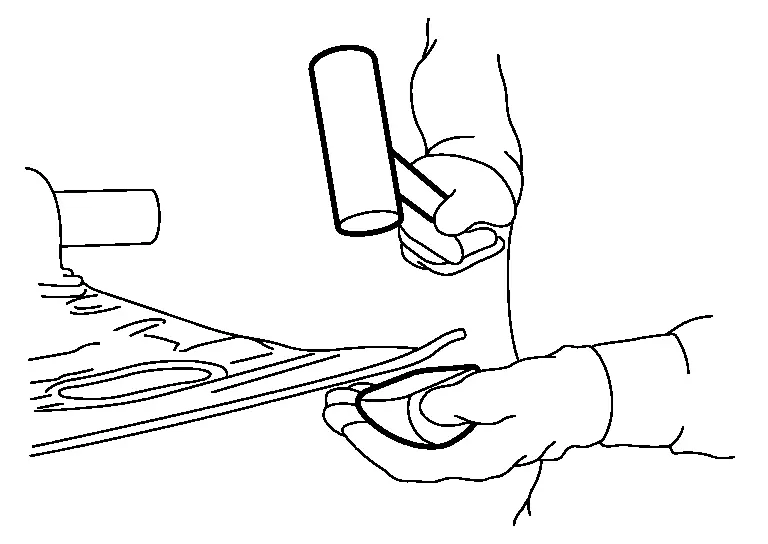
Apply wash primer and let it dry for 1 hour at 20 °C before applying body filler.

Use putty that can be used for aluminum panels. Do not perform forced drying because the coefficient of linear expansion is twice as much as that of sheet steel.

Heating Repair

While hammering work is being performed during the rough repair stage, the area needs to be heated. First, cover your hand with a glove (cloth material), and then place hand on the reverse side of the panel near the repair area. Apply heat to the entire repair area using a gas burner (oxy-acetylene gas welder) until your covered hand feels heat.
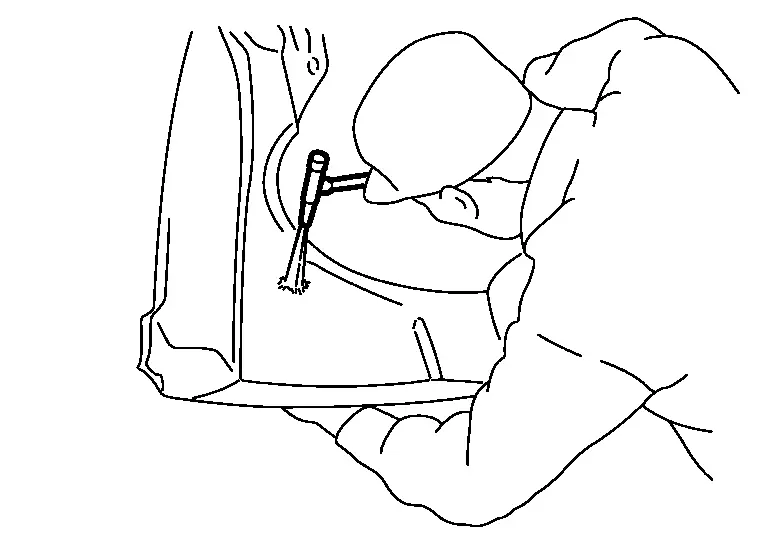
Shrinking

(1) FLAME SHRINKING

  • The area should be heated to approximately 250 °C.

    Aluminum alloy panels do not turn red when heated like steel plates. Prior to heating up the panel you are trying to repair, first practice with a scrap piece to get a good idea of how much heat is needed. This way the number of passes with the gas burner needed to achieve the correct temperature can be determined.

  • A thermometry pen may be applied to the repair area before heat application. Apply the thermometry pen to the heated part. Check if the thermometry pen is melted to judge if the temperature on the heated area is within the range of the specified temperature. When measuring temperature, use two thermometry pens of different specified temperatures. This allows the top and bottom of the temperature range to be judged accurately.
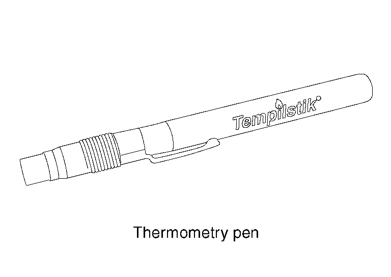
    (Example: Tempilstik or equivalent)

  • The heat conduction efficiency of aluminum alloy panel is approximately twice that of steel plate, which allows heat to be absorbed and released at a faster rate. Hammering [(b) in the figure] and rapid cooling work [(c) in the figure] must be performed while the area is still hot.
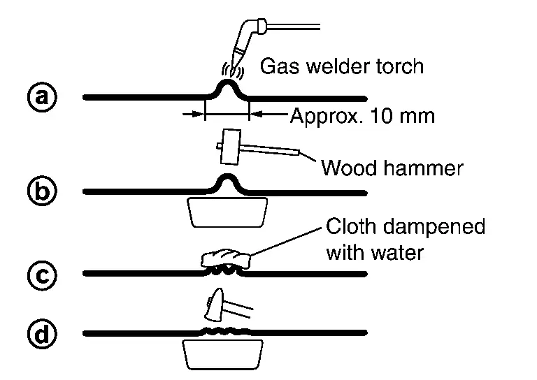
  • Don't use a shrinking hammer because it causes a crack.

(2) SHRINKING BY ELECTRIC WELDING

Shrinking with an electric welder is easier than with a gas burner, however this method leaves spark marks, scratches, carbon deposits, and oxide film on the panel surface.

For this reason, as an undercoating preparation, the panel surface must be cleaned using silicon off and a stainless steel wire brush.

When spark marks and scratches are large, the impurities are first completely removed using a wire brush, and then wash primer and putty are applied.

Precautions during Assembly

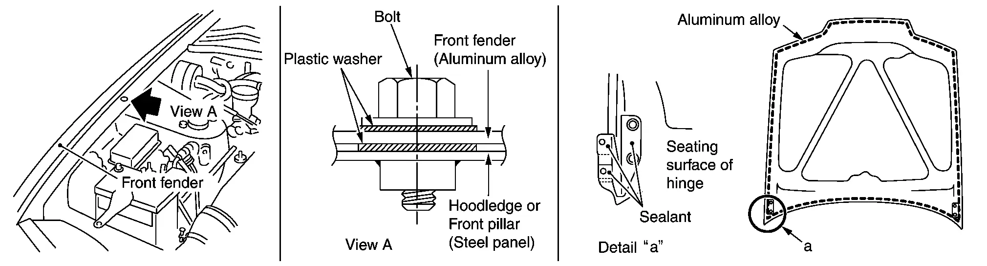
When installing parts, insulating materials such as resin washers (bolts at front fender) and anti-corrosion sealant (hood hinges) are inserted between the aluminum alloy panel and steel plates to prevent contact corrosion which occurs where different metals touch.
Welding (aluminum)

Welding (Aluminum)

To repair a crack or a hole in a steel plate, welding is usually used. Either oxygen and acetylene gas welding, arc welding, or brazing is commonly used. For aluminum alloy panels, TIG or MIG welding, which use inert gases (argon gas) as a shield gas, are usually used. This is because aluminum alloy has the following special features.

  • Its melting temperature is lower than iron, however the specific heat and latent heat are higher. It also has good conductivity. For these reasons, a large amount of heat must be applied in a very short time.

  • The melting point of aluminum alloy oxidized film is 2 °C. In order to remove this film, cleaning by argon welding (TIG welding, MIG welding) or flux treatment is required.

  • Not removing oxidized films results in incomplete fusion or blowholes.

  • Heat expansion and contraction is approximately twice that of iron, which allows for easy distortion by welding.

Comparision of Chemical and Physical Properties between Aluminum and Iron

PropertyAluminum alloyIronEffect of welding
Melting temperature °C (°F)

560 - 640

(1,040 - 1,184)

600 × 2.5

(1,112 × 2.5)
  • Aluminum alloy melts before it turns red.

  • This makes it difficult to judge the temperature.

Heat conduction efficiency

cal/cm/sec/°C (BTU in/m2/h/°F)

0.28

(812.69)

0.28 × 0.57

(812.69 × 0.57)
Large amount of heat in a short time required for welding.
Modulus of elasticity kg/mm2 (lb/in2)

7,000

(9,646,875)

7,000 × 3

(9,646,875 × 3)
Easily deformed and very fragile.

Coefficient of linear expansion

(10-6)
23.8 23.8 × 0.5
Conductivity (%) 30 30 × 0.52 Large current flow is required when compared to iron.
Oxidized film Al2 O3 Fe2 O3 The melting point of aluminum alloy oxidized film is 2 °C. In order to remove this film, cleaning by argon welding or flux treatment is required.

Filler Metal

For a filler metal, TIG welding rods and MIG welding electrode wires are available. Use filler metal that is suitable to the parent metal.

Main selection standards of filler metal
Parent metalFiller metal
Front fender, hood: 5000 series, 6000 series A5356
Door: 6000 series A5356

TIG Welding

TIG is the abbreviation for tungsten inert gas shielded arc welding. TIG has the following special features.

Special features

  • Initial cost of the equipment is low, as is maintenance expense.
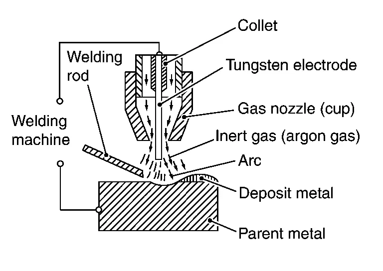
  • For ordinary electric power, high frequency alternating current is used.

  • Easy to learn in a short time.

  • Excellent strength and anti-corrosion properties.

  • Ideal for welding instruction and training.

MIG Welding

MIG is the abbreviation for metal inert gas shielded arc welding. MIG welding has the following special features.

(1) NORMAL MIG WELDING

MIG welding is the most commonly used welding method. As shown in the figure, a wire serving as an electrode is continuously fed into the welding area, and an arc is generated between the wire tip and the parent metal. Normally, an electrode wire measuring 1.2 mm - 1.4 mm (0.047 in - 0.055 in) in diameter, with an electrical current of 110 A - 360 A, is used for welding a plate having a thickness of 2 mm (0.079 in) or more.

(2) SHORT ARC MIG WELDING METHOD

When welding a thin plate, a short arc welding method is generally used.
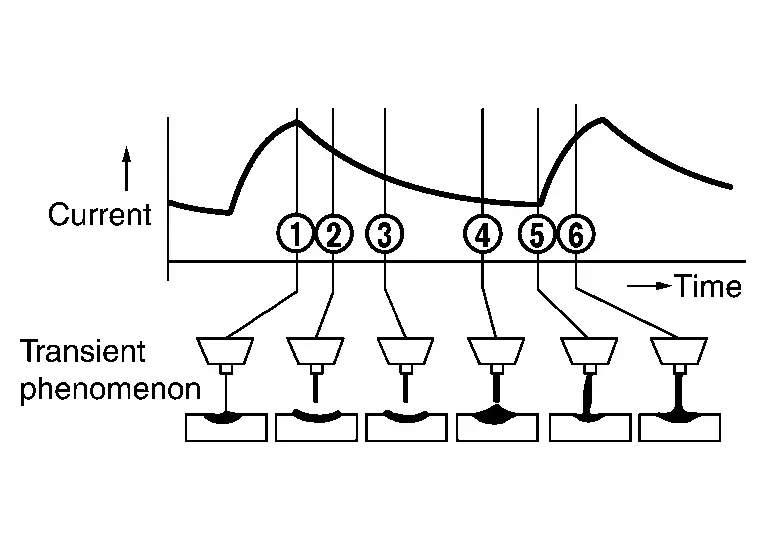
  • As shown in the figure, a short circuit and arc pattern is repeated.

  • When compared to ordinary MIG welding, using this short circuit transient method requires less heating, and therefore welding of a thin plate measuring 1 mm (0.04 in) in thickness can be accomplished.

  • The short arc welding conditions are shown below.

    For the torch in the short arc welding, a thin wire measuring 0.8 mm - 1.2 mm (0.031 in - 0.047 in) in diameter and wound in a small spool is installed.

Plate thickness

t = mm (in)
Shape of welding

Current

(A)

Voltage

(V)
Argon flow rate (US gal, Imp gal)/minWelding speed mm (in)/min
1 (0.04)
45 12 13 (3-3/8, 2-7/8) 600 (23.62)
2 (0.08) 85 15 15 (4, 3-1/4) 600 (23.62)
3 (0.12) 120 22 15 (4, 3-1/4) 600 (23.62)

(3) PULSED ARC WELDING METHOD

To enable spray transfer, even in the current range, which is equivalent to or lower than the critical current (spray transfer limiting current), pulse waveform is added to this welding method. Because this method allows stable penetration and bead shape while preventing heat gain, it is suitable for thin plate welding.

LOW PULSE FUNCTION

  • In addition to the pulse function, this function makes it easier to create imbricate bead shape.

  • It is effective in preventing burn through during the thin plate welding and the welding of panels with a gap present in between.
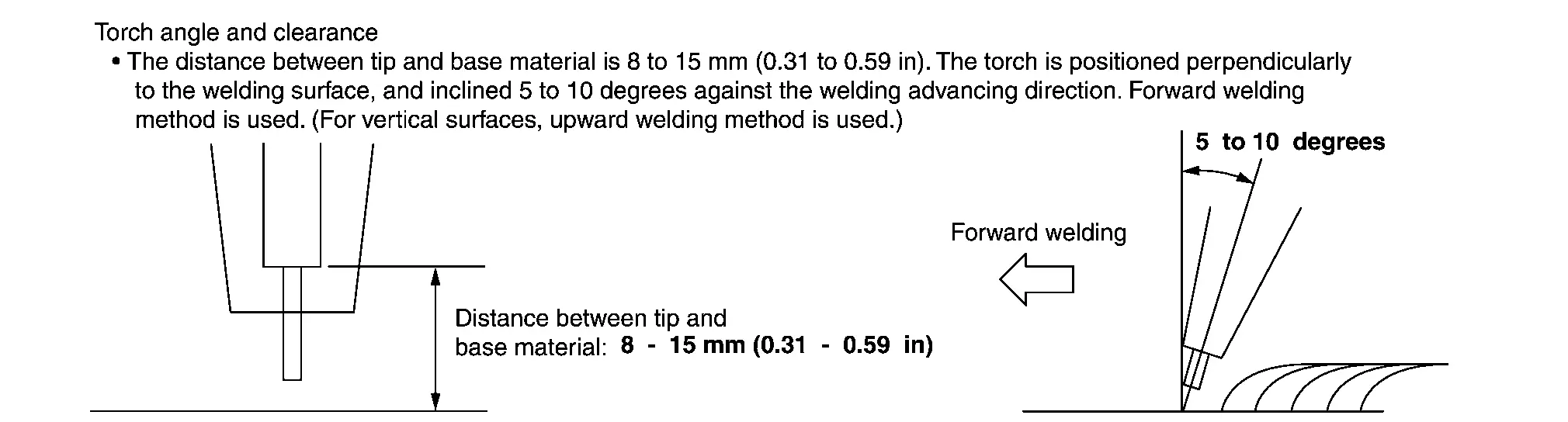
MIG Welding Method

(1) PLUG WELDING

MIG plug welding method is used to repair the spot welded portions.

Keep the upper panel and lower panel tightly together. Before welding, contact closely the points to be plug welded.

Observe the welding condition described in the Body Repair Manual.

(a) Welding condition (plug welding)

Basically, the following welding conditions are intended for horizontal welding. Therefore, depending on the welding direction, adjustment may be necessary.
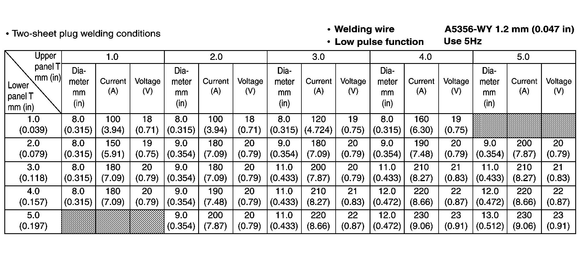
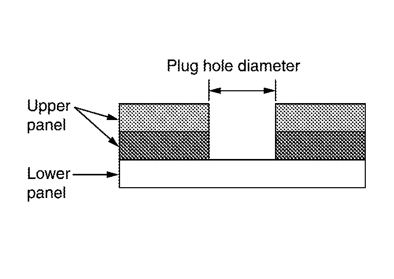
(b) Three-sheet plug welding condition

Consider the total thickness of two upper panels as the upper panel thickness. Using this thickness, apply the two-sheet plug welding conditions to set plug hole diameter, current, and voltage.
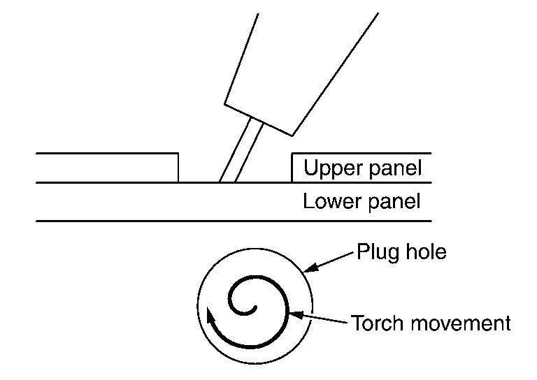
(c) Torch movement

  • Thickness of lower panel

    1.4 mm (0.055 in) or less

    Weld from the plug hole circumference toward the center in a circular motion.

  • Thickness of lower panel

    1.5 mm (0.059 in) or more

    Weld from the plug hole center toward the circumference in a circular motion.

(d) Backing block

When thin panels are plug welded, a backing block, as shown in the figure, is placed on the underside of the panels, and fixed onto the plug hole side with a clamp.
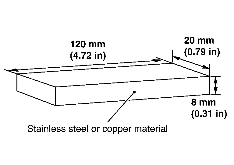
This is to prevent thin panels from burning through.

For locations where backing strips cannot be applied, be careful not to burn through.

(2) FILLET WELDING

  • Before welding, contact closely the points to be fillet welded.

  • Observe the welding conditions and lengths specified in the Body Repair Manual.

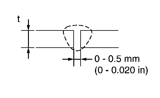
  • Set the welding range for the fillet welding cross section so that it is same as the panel thickness or wider. When the panels have different thicknesses, perform welding according to the welding conditions applicable to the thinner panel.
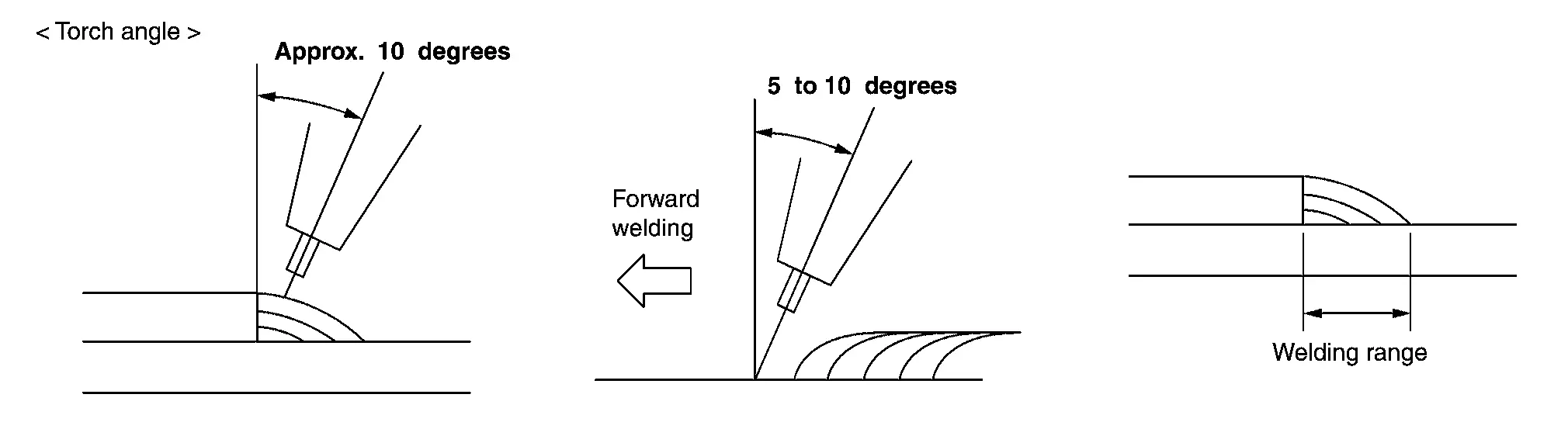
(3) SLOT WELDING

  • Before welding, contact closely the points to be slot welded.

  • Observe the welding conditions specified in the Body Repair Manual.

  • Welding range is from 10 mm (0.39 in) before the slot to 10 mm (0.39 in) after the slot.
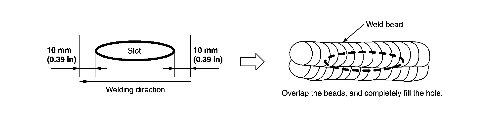
(4) BUTT WELDING

Observe the welding conditions specified in the parts replacement procedure.
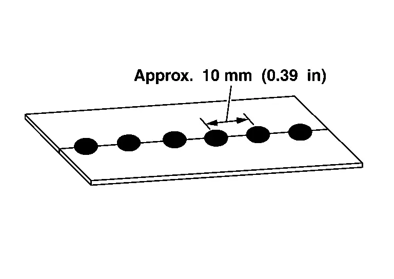
  1. Tack welding: Temporarily, but securely weld at approximately 10 mm (0.39 in) intervals.

  2. Remove aluminum oxides and magnesium oxides generated at tack welded points. Not doing so results in a welding malfunction.

  3. Regular welding.

Precautions during Welding

  • Wear long sleeved work uniform, work cap, and safety shoes. Wear safety goggles, gloves, earplugs, and dustproof respirator if necessary.

  • MIG arc welding for aluminum plates emits sparks. Do not stare directly at them. Before working, be sure to wear protectors to avoid getting burned.

  • Always perform pre-treatment of the parent metal.

    Dirt and oxidization film on the parent metal will cause defective welding. The following pre-treatment should be performed prior to welding. Oil film should be cleaned using Silicon Off or white gasoline.

    Surface should then be polished using a thin wire stainless steel brush.

    Oxide film is reproduced in approximately 30 minutes to 1 hour.

    Therefore, it is best to perform the pre-treatment immediately before welding.

    Even if pre-treatment for various locations has already been performed, it is necessary to use a wire brush again immediately before welding.

  • Use filler metal (welding rod or welding wire) that is suitable for the parent metal.

  • Filler metal used for aluminum welding flows easier than for steel welding, and therefore the welding surface should be in the horizontal position.

  • For TIG and MIG welding, even a 0.5 m/s (1.6 ft/s) breeze will greatly effect the seal. When performing welding outside, select a place where dust and moisture are minimized. A shelter should be constructed for protection from wind or rain.

  • Remove paint film of the welding portions and electrodeposition coating of the service parts using a disc sander.

    When removing, be careful not to excessively sand aluminum alloy base material.

Body Straightening (aluminum)

Securing the Vehicle

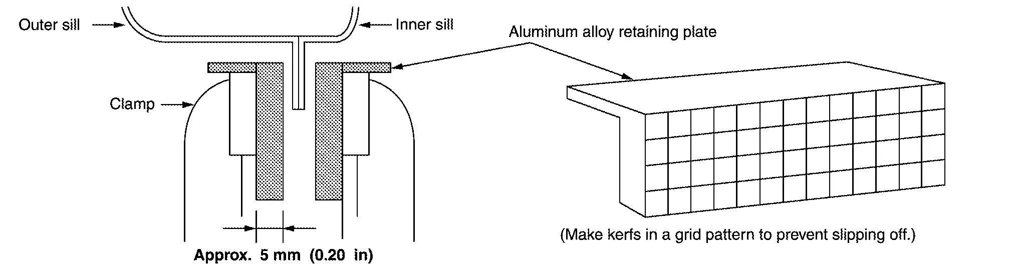
When fixing the aluminum body to the body straightening equipment, set an aluminum alloy retaining plate [thickness: approximately 5 mm (0.20 in)] in the clamp to prevent sill flange damage.
Frame Straightening

  • Buckling portions have been work hardened. When straightening frames, straighten by pulling out while heating with oxy-acetylene gas welder. Unlike steel plates, aluminum alloy does not change color even when heated. Use a noncontact type thermometer or thermometry pen to control the temperature. Be careful not to overheat.

    <Reference> Melting point of aluminum alloy: approximately 640 °C

    Possible heating temperature
    Extrusion molding material (6000 series) : 110 °C
    Press molding material (5000 series) : 350 °C
  • During pulling work, pulling fully with large force causes weld to peel (spot weld peeling or cracks are generated in fillet weld). Pull out gradually.

  • Aluminum alloy has high thermal conductivity. When heating, remove interior equipment and other related parts extensively.