Audio, Visual & Navigation System - System Description

In this manual: Audio, Visual & Navigation System - System Description
General Information — 8Engine :: Engine Mechanical — 19Engine Lubrication System - Precautions. Preparation — 1Engine Lubrication System - Lubrication System (System Description). Engine Oil Pressure (Basic Inspection). Service Data and Specifications (SDS) — 1Engine Cooling System - Precautions. Preparation. Service Data and Specifications (SDS) — 1Engine Cooling System - Engine Coolant — 1Engine Control System - System Description — 1System Description - Component Parts ++ — 1System Description - System ++ — 1Engine Control System - Ecu Diagnosis Information — 1Ecu Diagnosis Information - Ecm ++ — 1Engine Control System - Basic Inspection — 1Basic Inspection - Diagnosis and Repair Workflow ++ — 1Basic Inspection - Basic Inspection ++ — 1Basic Inspection - Additional Service When Replacing Ecm ++ — 1Basic Inspection - Fuel Pressure Check ++ — 1Basic Inspection - How to Set Srt Code ++ — 1Basic Inspection - How to Erase Permanent Dtc ++ — 1Engine Control System - Dtc/circuit Diagnosis — 1Engine Control System - Symptom Diagnosis — 1Engine Control System - Periodic Maintenance — 1Engine Control System - Removal and Installation — 1Fuel System - Precautions. Preparation. Service Data and Specifications (SDS) — 1Fuel System - Fuel System (Periodic Maintenance). Fuel Level Sensor Unit (Disassembly and Assembly) — 1Exhaust System - Precautions. Preparation — 1Exhaust System - Exhaust System (Periodic Maintenance). Exhaust System (Removal and Installation) — 1Starting System - Precautions. Preparation. Starter Motor (Service Data and Specifications (sds)) — 1Starting System - Diagnosis and Repair Work Flow — 1Starting System - Starting System (Symptom Diagnosis). Starter Motor (Removal and Installation) — 1Accelerator Control System - Precautions. Service Data and Specifications (SDS) — 1Accelerator Control System - Accelerator Pedal Assembly — 1Transmission & Driveline :: Transaxle & Transmission — 21Driveline - System Description — 1Transfer: Ty92b - Ecu Diagnosis Information. Awd Control Unit ++ — 1Driveline - Basic Inspection — 1Driveline - Dtc/circuit Diagnosis — 1Driveline - Symptom Diagnosis — 1Driveline - Removal and Installation — 1Transfer: Ty92b - Unit Removal and Installation. Transfer Assembly ++ — 1Driveline - Unit Disassembly and Assembly — 1Driveline - Basic Inspection — 1Driveline - Removal and Installation — 1Driveline - Unit Disassembly and Assembly — 1Front Axle - Precautions. Preparation — 1Front Axle - Noise, Vibration and Harshness (nvh) Troubleshooting (Symptom Diagnosis). Service Data and Specifications (SDS) — 1Front Axle - Front Drive Shaft Boot — 1Front Axle - Front Drive Shaft — 1Rear Axle - Precautions. Preparation. Service Data and Specifications (SDS) — 1Rear Axle - Noise, Vibration and Harshness (nvh) Troubleshooting — 1Rear Axle - Rear Drive Shaft — 1Suspension :: Front Suspension — 7Rear Suspension - Precautions. Preparation — 1Rear Suspension - Noise, Vibration and Harshness (nvh) Troubleshooting (Symptom Diagnosis). Service Data and Specifications (SDS) — 1Rear Suspension - Rear Suspension Assembly — 1Road Wheels & Tires - Precautions — 1Road Wheels & Tires - Preparation. Bcm (Ecu Diagnosis Information). Service Data and Specifications (SDS) — 1Road Wheels & Tires - System — 1Brakes :: Brake System — 9Parking Brake System - Precautions. Preparation — 1Parking Brake System - System — 1Vdc/tcs/abs - Precautions ++ — 1Brake Control System - System Description — 1System Description - Component Parts ++ — 1System Description - System ++ — 1Brake Control System - Basic Inspection — 1Brake Control System - Symptom Diagnosis — 1Brake Control System - Removal and Installation — 1Brake Control System - System Description — 1Brake Control System - Dtc/circuit Diagnosis — 1Brake Control System - Removal and Installation — 1Brake Control System - System Description — 1Brake Control System - Basic Inspection — 1Brake Control System - Symptom Diagnosis — 1Brake Control System - System Description — 1Brake Control System - Basic Inspection — 1Brake Control System - Symptom Diagnosis — 1Steering :: Steering System — 9Steering Control System - Precautions — 1Steering Control System - System — 1Steering Control System - Eps Control Unit (Ecu Diagnosis Information. Removal and Installation) — 1Restraints :: Seat Belt — 7Srs Air Bag - Precautions. Preparation — 1Srs Air Bag - Collision Diagnosis — 1Srs Air Bag - Occupant Classification System — 1Srs Air Bag Control System - Precautions — 1Srs Air Bag Control System - System — 1Srs Air Bag Control System - Diagnosis Sensor Unit — 1Srs Air Bag Control System - Inspection and Adjustment — 1Ventilation, Heater & Air Conditioner :: Ventilation System — 6Heater & Air Conditioning System - Precautions — 1Heater & Air Conditioning System - Preparation — 1Heater & Air Conditioning System - Component Parts — 1Heater & Air Conditioning System - Diagnosis and Repair Work Flow — 1Heater & Air Conditioning System - Compressor — 1Heater & Air Conditioning System - Cooler Pipe and Hose — 1Heater & Air Conditioning System - Condenser. Condenser — 1Heater & Air Conditioning System - Heating and Cooling Unit Assembly — 1Heater & Air Conditioning System - Service Data and Specifications (SDS) — 1Heater & Air Conditioning Control System - System Description — 1System Description - Component Parts ++ — 1System Description - System ++ — 1System Description - Operation ++ — 1Heater & Air Conditioning Control System - Ecu Diagnosis Information — 1Heater & Air Conditioning Control System - Basic Inspection — 1Heater & Air Conditioning Control System - Dtc/circuit Diagnosis — 1Heater & Air Conditioning Control System - Symptom Diagnosis — 1Heater & Air Conditioning Control System - Removal and Installation — 1Body Interior :: Interior — 8Instrument Panel - Precautions. Preparation. Clip List — 1Instrument Panel - Squeak and Rattle Trouble Diagnoses — 1Instrument Panel - Cluster Lid C — 1Seat - Precautions — 1Seat - Preparation. Clip List — 1Seat - Component Parts — 1Seat - System — 1Seat - Diagnosis and Repair Work Flow — 1Seat - Front Seat — 1Seat - Second Row Seats — 1Seat - Third Row Seats — 1Seat - Front Seat — 1Seat - Second Row Seat — 1Seat - Third Row Seat — 1Automatic Drive Positioner - Precautions. Preparation — 1Automatic Drive Positioner - System — 1Automatic Drive Positioner - Diagnosis and Repair Work Flow — 1Automatic Drive Positioner - Inspection and Adjustment — 1Body Exterior, Doors, Roof & Vehicle Security :: Door & Lock — 38Security Control System - Precautions — 1Security Control System - System — 1Security Control System - Ecm, Bcm, Intelligent Key Unit, Ipdm E/r — 1Security Control System - Vehicle Security System Cannot Be Set — 1Glass & Window System - Precautions. Preparation — 1Glass & Window System - Squeak and Rattle Trouble Diagnoses — 1Power Window Control System - Precautions. Preparation — 1Power Window Control System - Power Supply and Ground Circuit — 1Power Window Control System - Power Window Motor Circuit — 1Power Window Control System - Front Power Window Rh Alone Does Not Operate — 1Power Window Control System - Rear Lh Side Power Window Alone Does Not Operate — 1Power Window Control System - Rear Rh Side Power Window Alone Does Not Operate — 1Roof - Precautions. Preparation — 1Roof - Power Supply and Ground Circuit — 1Roof - Moonroof Switch Assembly — 1Roof - Lin Communication Circuit — 1Roof - Auto Operation Does Not Operate — 1Roof - Anti-Pinch Function Does Not Operate — 1Exterior - Precautions. Preparation. Clip List (Preparation) — 1Exterior - Squeak and Rattle Trouble Diagnoses — 1Exterior - Fender Protector — 1Exterior - Over Fender — 1Exterior - Under Cover — 1Exterior - Roof Side Rail — 1Body Repair - Service Information — 1Service Information - Sheet Metal Work ++ — 1Service Information - Body Welding and Precautions ++ — 1Service Information - Safety and Health ++ — 1Service Information - Repairing Procedures and Precautions ++ — 1Body Repair - Precaution — 1Body Repair - Preparation — 1Body Repair - Removal and Installation — 1Driver Controls :: Mirrors — 8Exterior Lighting System - System Description — 1System Description - Component Parts ++ — 1Exterior Lighting System - Basic Inspection — 1Exterior Lighting System - Dtc/circuit Diagnosis — 1Exterior Lighting System - Symptom Diagnosis — 1Exterior Lighting System - Periodic Maintenance — 1Exterior Lighting System - Removal and Installation — 1Interior Lighting System - Precautions. Preparation — 1Interior Lighting System - Component Parts. Interior Lighting System — 1Interior Lighting System - System — 1Interior Lighting System - Diagnosis and Repair Work Flow — 1Interior Lighting System - Interior Lighting System Symptoms (Symptom Diagnosis). Bcm (Ecu Diagnosis Information). Service Data and Specifications (SDS) — 1Interior Lighting System - Foot Lamp — 1Wiper & Washer - Precautions — 1Wiper & Washer - Preparation. Bcm, Ipdm E/r (Ecu Diagnosis Information). Service Data and Specifications (SDS) — 1Wiper & Washer - System — 1Wiper & Washer - Diagnosis and Repair Work Flow — 1Defogger - Precautions. Bcm, A/c Auto Amp. (Ecu Diagnosis Information) — 1Defogger - Diagnosis and Repair Work Flow — 1Horn - Precautions — 1Electrical & Power Control :: Power Outlet — 13Body Control System - Precautions. Preparation — 1Body Control System - Component Parts — 1Body Control System - System — 1Body Control System - Diagnosis System (bcm) — 1Body Control System - Bcm — 1Lan System - System Description — 1Lan System - System Description — 1Lan System - Dtc/circuit Diagnosis — 1Lan System - System Description — 1Lan System - Dtc/circuit Diagnosis — 1Power Control System - System Description — 1Power Control System - Basic Inspection — 1Power Control System - Dtc/circuit Diagnosis — 1Power Control System - System Description — 1Power Control System - Basic Inspection — 1Power Control System - Dtc/circuit Diagnosis — 1Power Control System - Removal and Installation — 1Charging System - Precautions. Preparation. Ecm, Ipdm E/r (Ecu Diagnosis Information) — 1Charging System - Diagnosis and Repair Work Flow — 1Charging System - Charging System (Symptom Diagnosis). Generator (Removal and Installation). Service Data and Specifications (SDS) — 1Power Supply, Ground & Circuit Elements - Precautions. Preparation. Service Data and Specifications (SDS) — 1Driver Information & Multimedia :: Meter, Warning Lamp & Indicator — 25Warning Chime System - Application Notice (How to Use This Manual). Precautions — 1Warning Chime System - System — 1Warning Chime System - Diagnosis System (combination Meter) — 1Warning Chime System - Bcm, Combination Meter (Ecu Diagnosis Information). Diagnosis and Repair Work Flow (Basic Inspection) — 1Sonar System - Precautions. Preparation — 1Sonar System - Sonar Control Unit — 1Dtc/circuit Diagnosis - B2720 Corner Sensor [rl] ++ — 1Audio, Visual & Navigation System - System Description — 1System Description - Component Parts ++ — 1System Description - System ++ — 1Audio, Visual & Navigation System - Ecu Diagnosis Information — 1Audio, Visual & Navigation System - Basic Inspection — 1Audio, Visual & Navigation System - Dtc/circuit Diagnosis — 1Dtc/circuit Diagnosis - Multi Av (av Control Unit) ++ — 1Audio, Visual & Navigation System - Symptom Diagnosis — 1Symptom Diagnosis - Multi Av System ++ — 1Audio, Visual & Navigation System - Removal and Installation — 1Audio, Visual & Navigation System - System Description — 1Audio, Visual & Navigation System - Ecu Diagnosis Information — 1Audio, Visual & Navigation System - Basic Inspection — 1Audio, Visual & Navigation System - Dtc/circuit Diagnosis — 1Audio, Visual & Navigation System - Symptom Diagnosis — 1Audio, Visual & Navigation System - Removal and Installation — 1Audio, Visual & Navigation System - System Description — 1Audio, Visual & Navigation System - Basic Inspection — 1Audio, Visual & Navigation System - Dtc/circuit Diagnosis — 1Audio, Visual & Navigation System - Symptom Diagnosis — 1Audio, Visual & Navigation System - Removal and Installation — 1Audio, Visual & Navigation System - System Description — 1Audio, Visual & Navigation System - Basic Inspection — 1Audio, Visual & Navigation System - Dtc/circuit Diagnosis — 1Audio, Visual & Navigation System - Symptom Diagnosis — 1Audio, Visual & Navigation System - Removal and Installation — 1Cruise Control & Driver Assistance :: Cruise Control System — 17Driver Assistance System - System Description — 1Driver Assistance System - Basic Inspection — 1Driver Assistance System - Dtc/circuit Diagnosis — 1Driver Assistance System - System Description — 1System Description - Component Parts ++ — 1System Description - System ++ — 1System Description - Operation ++ — 1System Description - Handling Precaution ++ — 1Driver Assistance System - Ecu Diagnosis Information — 1Driver Assistance System - Basic Inspection — 1Basic Inspection - Distance Sensor Alignment ++ — 1Basic Inspection - Camera Aiming Adjustment ++ — 1Basic Inspection - Action Test ++ — 1Driver Assistance System - Dtc/circuit Diagnosis — 1Dtc/circuit Diagnosis - Laser/radar (distance Sensor) ++ — 1Dtc/circuit Diagnosis - Lane Camera (front Camera Unit) ++ — 1Driver Assistance System - Symptom Diagnosis — 1Driver Assistance System - Removal and Installation — 1Driver Assistance System - System Description — 1System Description - System ++ — 1Driver Assistance System - Basic Inspection — 1Driver Assistance System - Dtc/circuit Diagnosis — 1Drive Mode System - Precautions — 1Drive Mode System - Component Parts. Drive Mode System — 1Drive Mode System - System — 1Drive Mode System - Diagnosis and Repair Work Flow — 1Drive Mode System - Drive Mode Select Switch Circuit — 1Maintenance - Precautions. Preparation — 1Maintenance - General Maintenance — 1Maintenance - Periodic Maintenance — 1Maintenance - Recommended Fluids and Lubricants — 1Maintenance - Engine Maintenance — 1Maintenance - Chassis and Body Maintenance — 1Engine Lubrication System - Periodic Maintenance — 1Engine Lubrication System - Removal and Installation — 1Engine Cooling System - System Description — 1Engine Cooling System - Removal and Installation — 1Engine Control System - Vq35dd — 1Fuel System - Removal and Installation — 1Starting System - System Description — 1Starting System - Dtc/circuit Diagnosis — 1Driveline - Transfer: Ty92b — 1Driveline - Rear Propeller Shaft: 3fcj-Cvj — 1Driveline - Rear Final Drive: R145 — 1Front Axle - Periodic Maintenance — 1Front Axle - Removal and Installation — 1Rear Axle - Periodic Maintenance — 1Rear Axle - Removal and Installation — 1Rear Suspension - Removal and Installation — 1Road Wheels & Tires - System Description — 1Road Wheels & Tires - Basic Inspection — 1Road Wheels & Tires - Dtc/circuit Diagnosis — 1Road Wheels & Tires - Symptom Diagnosis — 1Road Wheels & Tires - Periodic Maintenance — 1Road Wheels & Tires - Removal and Installation — 1Parking Brake System - System Description — 1Parking Brake System - Basic Inspection — 1Parking Brake System - Dtc/circuit Diagnosis — 1Parking Brake System - Symptom Diagnosis — 1Parking Brake System - Removal and Installation — 1Brake Control System - Vdc/tcs/abs — 1Brake Control System - Automatic Brake Hold — 1Brake Control System - Automatic Emergency Braking — 1Brake Control System - Rear Automatic Braking — 1Steering Control System - System Description — 1Steering Control System - Basic Inspection — 1Steering Control System - Dtc/circuit Diagnosis — 1Steering Control System - Symptom Diagnosis — 1Srs Air Bag - Removal and Installation — 1Srs Air Bag Control System - System Description — 1Srs Air Bag Control System - Basic Inspection — 1Srs Air Bag Control System - Symptom Diagnosis — 1Heater & Air Conditioning System - Symptom Diagnosis — 1Heater & Air Conditioning System - Periodic Maintenance — 1Heater & Air Conditioning Control System - Automatic Air Conditioning — 1Instrument Panel - Removal and Installation — 1Instrument Panel - Unit Disassembly and Assembly — 1Seat - Ecu Diagnosis Information — 1Seat - Dtc/circuit Diagnosis — 1Seat - Symptom Diagnosis — 1Automatic Drive Positioner - System Description — 1Automatic Drive Positioner - Ecu Diagnosis Information — 1Automatic Drive Positioner - Dtc/circuit Diagnosis — 1Automatic Drive Positioner - Symptom Diagnosis — 1Automatic Drive Positioner - Removal and Installation — 1Security Control System - System Description — 1Security Control System - Basic Inspection — 1Security Control System - Dtc/circuit Diagnosis — 1Security Control System - Symptom Diagnosis — 1Security Control System - Removal and Installation — 1Glass & Window System - Removal and Installation — 1Power Window Control System - System Description — 1Power Window Control System - Ecu Diagnosis Information — 1Power Window Control System - Basic Inspection — 1Power Window Control System - Dtc/circuit Diagnosis — 1Power Window Control System - Symptom Diagnosis — 1Power Window Control System - Removal and Installation — 1Roof - System Description — 1Roof - Ecu Diagnosis Information — 1Roof - Basic Inspection — 1Roof - Dtc/circuit Diagnosis — 1Roof - Symptom Diagnosis — 1Roof - Removal and Installation — 1Exterior - System Description — 1Exterior - Removal and Installation — 1Body Repair - Repair Information — 1Exterior Lighting System - Led Headlamp — 1Interior Lighting System - Dtc/circuit Diagnosis — 1Interior Lighting System - Removal and Installation — 1Wiper & Washer - System Description — 1Wiper & Washer - Dtc/circuit Diagnosis — 1Wiper & Washer - Symptom Diagnosis — 1Wiper & Washer - Removal and Installation — 1Defogger - System Description — 1Defogger - Dtc/circuit Diagnosis — 1Defogger - Symptom Diagnosis — 1Defogger - Removal and Installation — 1Horn - Removal and Installation — 1Body Control System - Basic Inspection — 1Body Control System - Dtc/circuit Diagnosis — 1Body Control System - Symptom Diagnosis — 1Body Control System - Removal and Installation — 1Lan System - Can Fundamental — 1Lan System - Can — 1Lan System - Can Gateway — 1Power Control System - Ipdm E/r — 1Power Control System - Power Distribution System — 1Charging System - System Description — 1Charging System - Dtc/circuit Diagnosis — 1Power Supply, Ground & Circuit Elements - System Description — 1Power Supply, Ground & Circuit Elements - Basic Inspection — 1Power Supply, Ground & Circuit Elements - Removal and Installation — 1Warning Chime System - System Description — 1Warning Chime System - Dtc/circuit Diagnosis — 1Warning Chime System - Symptom Diagnosis — 1Sonar System - System Description — 1Sonar System - Basic Inspection — 1Sonar System - Dtc/circuit Diagnosis — 1Sonar System - Symptom Diagnosis — 1Sonar System - Removal and Installation — 1Audio, Visual & Navigation System - Nissanconnect — 1Audio, Visual & Navigation System - Intelligent Around View Monitor System — 1Audio, Visual & Navigation System - Rear View Monitor System — 1Audio, Visual & Navigation System - Telematics System — 1Driver Assistance System - Adas Control Unit 2 — 1Driver Assistance System - Driver Assistance System — 1Driver Assistance System - Chassis Control — 1Drive Mode System - Removal and Installation — 1Dtc/circuit Diagnosis (C053c Wheel Speed Sensor ... U2141 Can Comm Circuit) — 1Dtc/circuit Diagnosis (P0011 Intake Valve Timing Control ... P0111 Iat Sensor) — 1Dtc/circuit Diagnosis (P0116 Engine Coolant Temperature Sensor ... P025b Fuel Pump Module a) — 1Dtc/circuit Diagnosis (P026b Injection Timing ... P0420 Three Way Catalyst Function) — 1Dtc/circuit Diagnosis (P0441 Evap Control System ... P0524 Engine Oil Pressure) — 1Dtc/circuit Diagnosis (P0532 A/c Refrigerant Pressure Sensor ... P064d Ecm) — 1Dtc/circuit Diagnosis (P06da Engine Oil Pressure Control Solenoid Valve ... P1217 Engine Over Temperature) — 1Dtc/circuit Diagnosis (P1220 Fuel Pump Control Module (fpcm) ... P1574 Ascd Vehicle Speed Sensor) — 1Dtc/circuit Diagnosis (P1575 Brake Switch ... P2101 Electric Throttle Control Function) — 1Dtc/circuit Diagnosis (P2118 Throttle Control Motor ... P34ac Electric Intake Valve Timing Control Actuator) — 1Dtc/circuit Diagnosis (Active Grille Shutter ... High Pressure Fuel Pump) — 1Dtc/circuit Diagnosis (Ignition Signal ... Variable Induction Air System) — 14012 C1040 Emergency Brake — 14013 C106a Wheel Sensor — 14014 C1078-55 Not Configuration — 14015 C10b4-98 Overheat — 14016 B1001 Lap Pre-Tensioner Lh — 14017 B0001 Driver Air Bag Module — 14018 B100e Knee Air Bag Module Rh — 14019 B142x Collision Detection — 1Dtc/circuit Diagnosis (B20c7-11 A/c Clutch ... B24a6-11 in-Vehicle Sensor) — 1Dtc/circuit Diagnosis (B24a6-15 in-Vehicle Sensor ... U2140-87 Can Comm Err (ecm)) — 1Dtc/circuit Diagnosis (C1f00-1c Control Unit ... C1f04-61 Brake Sw/stop Lamp Sw) — 1Dtc/circuit Diagnosis (C1f05-49 Front Camera Unit ... C1f70-87 Ethernet Circuit) — 1
~19min read
  • Component Parts
  • System
  • Diagnosis System (around View Monitor Control Unit)

Component Parts Nissan Pathfinder SUV

Intelligent Around View Monitor System

Component Parts Location
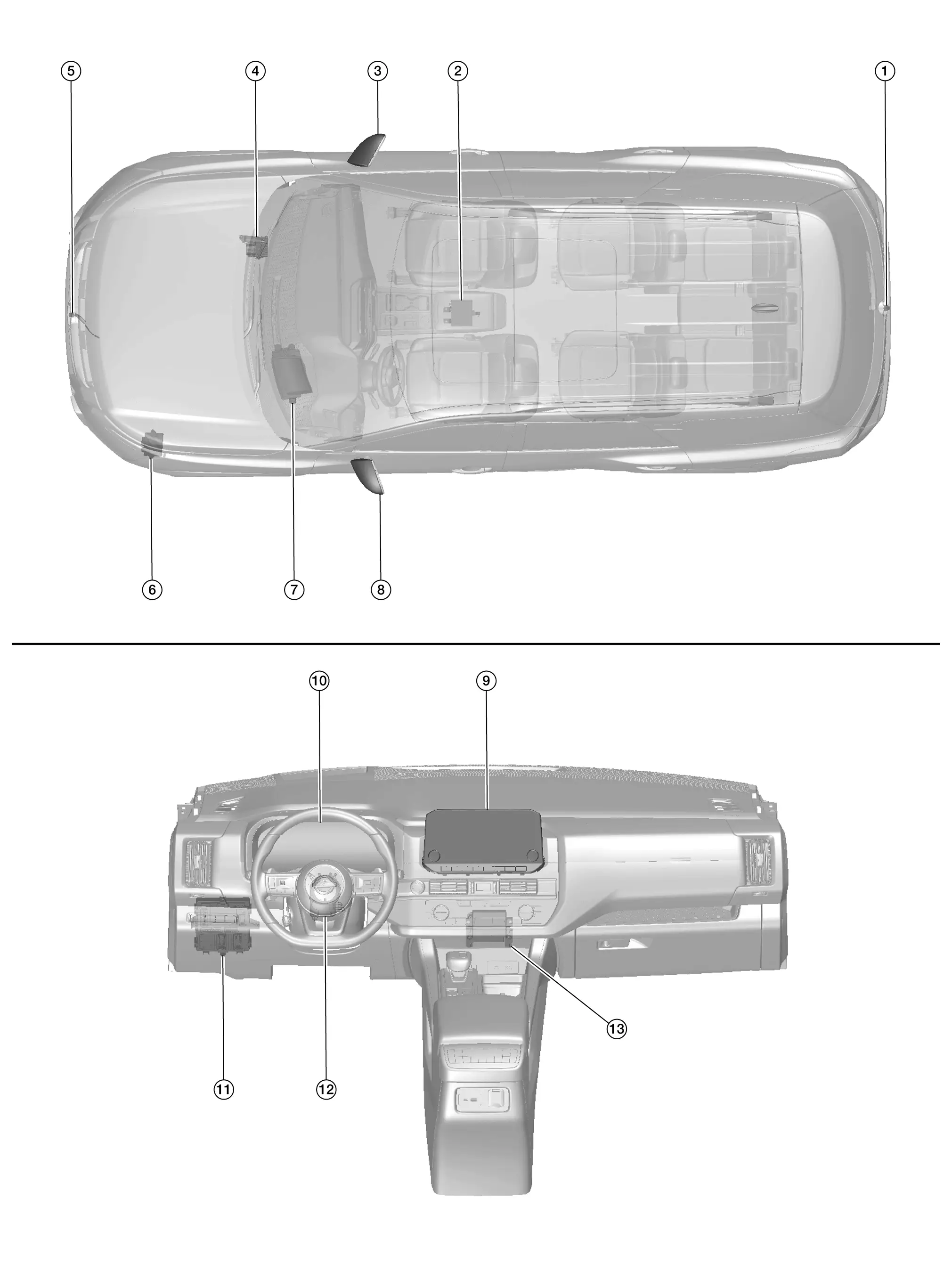
No.ComponentFunction
1. Rear camera Refer to Rear Camera.
2. Around view monitor control unit Refer to Around View Monitor Control Unit.
3. Side camera RH Refer to Side Camera.
4. ABS (Anti-lock Braking System) actuator and electric unit (control unit)

Provides around view monitor control unit with the following signals via CAN communication:

  • Nissan Pathfinder Vehicle speed signal.

  • Wheel speed signals.

Refer to Component Parts Location for detailed component location.
5. Front camera Refer to Front Camera.
6. TCM (Transmission Control Module)

Provides around view monitor control unit with the shift position signal via CAN communication.

Refer to Component Parts Location for detailed component location.
7. Head up display unit (if so equipped)

Provides AV control unit with the head up information signals via AV communication.

Refer to Component Parts Location (full TFT meter) or Component Parts Location (7 inch information display meter) for detailed component location.
8. Side camera LH Refer to Side Camera.
9. AV control unit Refer to AV Control Unit.
10. Combination meter
  • Provides around view monitor control unit with the MOD setting signal via CAN communication.

  • Provides AV control unit with the steering switch signals via AV communication.

  • Provides AV control unit with the following signals via CAN communication:

    • Nissan Pathfinder Vehicle speed signal.

    • Parking brake status signal.

Refer to Component Parts Location (full TFT meter) or Component Parts Location (7 inch information display meter) for detailed component location.
11. BCM (Body Control Module)

Provides around view monitor control unit with the door switch signals via CAN communication.

Refer to System Description.
12. Steering angle sensor Refer to Steering Angle Sensor.
13. Sonar control unit

Provides around view monitor control unit with the sonar indicator signal via CAN communication.

Refer to Component Parts Location for detailed component location.

AV Control Unit

  • An 8-inch (without navigation) or 9-inch (with navigation) color display with multi-touch control, an AM/FM electronic tuner radio with RDS and camera controller are integrated into the AV Control unit.

  • The color display is a high resolution monitor that includes touch panel functions.

Around View Monitor Control Unit

  • The around view monitor control unit is installed under the center console.
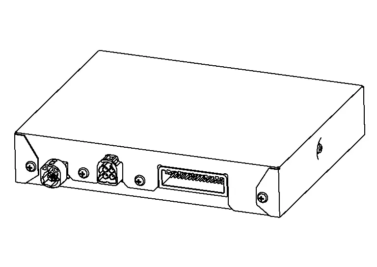
  • Necessary signals are transmitted/received to/from control unit via CAN communication.

  • Camera image signals received from each camera are converted/synthesized in the around view monitor control unit and transmitted to the AV control unit via LVDS.

  • Nissan Pathfinder Vehicle width guide lines, predicted course line, vehicle front guiding line and vehicle side line, tire icon, and Nissan Pathfinder vehicle icon are rendered with the around view monitor control unit and combined with camera image.

Front Camera

  • The front camera is installed in the front grille.
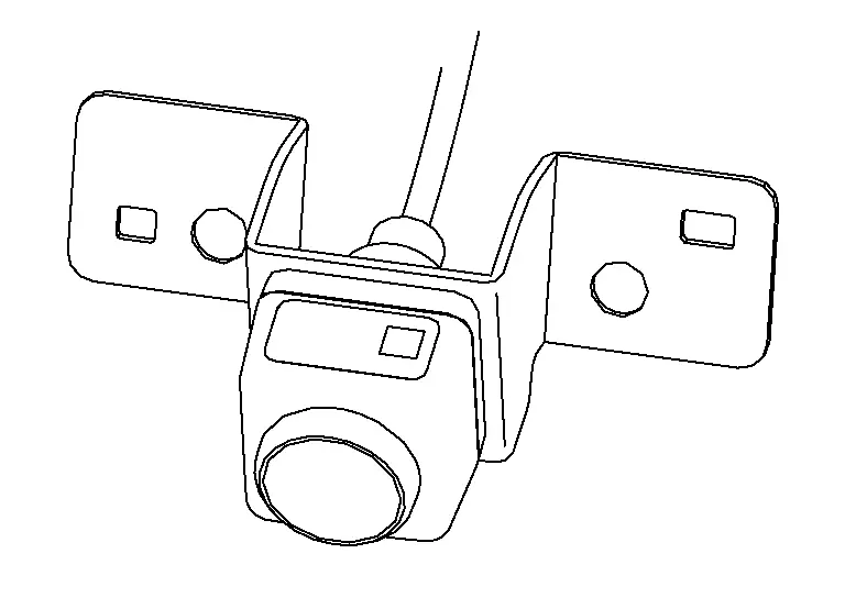
  • Image at the front of the Nissan Pathfinder vehicle is sent to the around view monitor control unit via LVDS.

Side Camera

  • The side camera is installed in the door mirror.
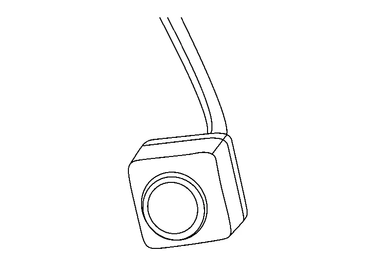
  • Images at the sides of the Nissan Pathfinder vehicle are sent to the around view monitor control unit via LVDS.

Rear Camera

  • The rear view camera is installed at the center of the back door finisher.
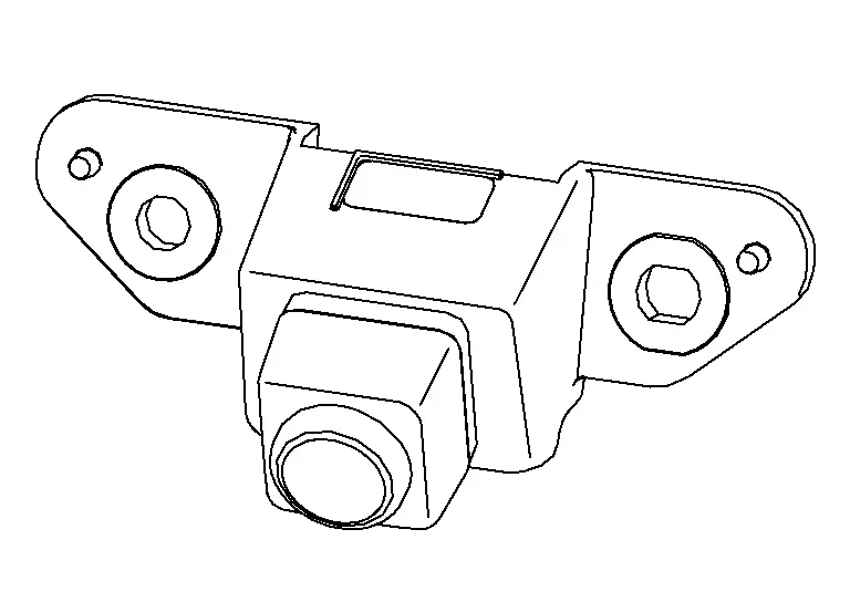
  • Image at the rear of the Nissan Pathfinder vehicle is sent to the around view monitor control unit via LVDS.

Steering Angle Sensor

  • Steering angle sensor is installed to the combination switch (spiral cable).
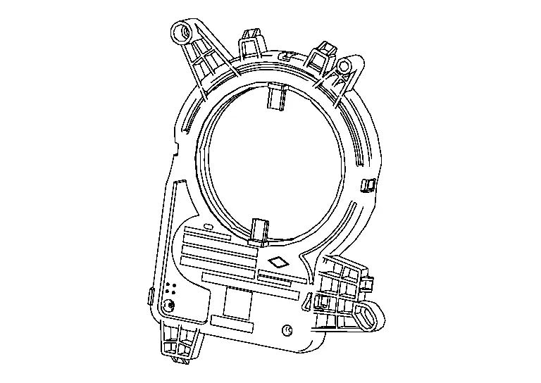
  • Steering angle sends the steering signal necessary for predictive course line of the front or rear view monitor to the around view monitor control unit via CAN communication.

System Nissan Pathfinder

System Description

SYSTEM DIAGRAM
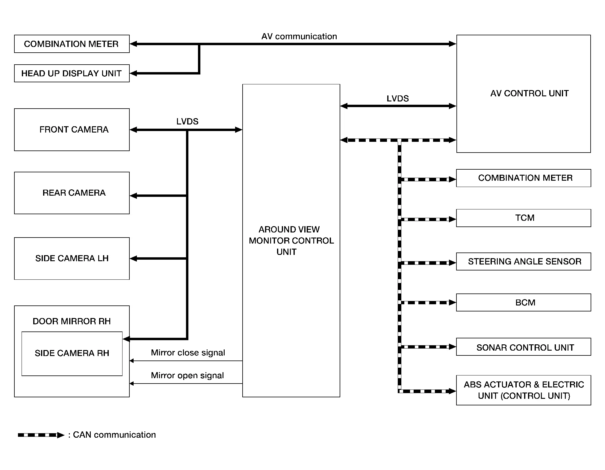
Around View Monitor Control Unit Input Signal (CAN Communication)

Transmit unitSignal name
ABS actuator and electric unit (control unit) Nissan Pathfinder Vehicle speed signal
Wheel speed signals
BCM Door switch signals
AV control unit Camera switch signal
Combination meter MOD setting signal
Sonar control unit Sonar indicator signal
TCM Shift position signal

AV Control Unit Input Signal (AV Communication)

Transmit unitSignal name
Combination meter Steering switch signal
Head up display unit Head up information signals

AV Control Unit Input Signal (CAN Communication)

Transmit unitSignal name
Combination meter
  • Nissan Pathfinder Vehicle speed signal

  • Parking brake status signal

DESCRIPTION

  • This system is equipped with wide-angle high-resolution cameras on the front and rear of the Nissan Pathfinder vehicle and on both right and left door mirrors. The images from front view, rear view, front-side view passenger side, and birds-eye view that shows the view from the top of the Nissan Pathfinder vehicle are displayed to monitor the vehicle surroundings.

  • Around view monitor control unit cuts out and expands the image received from each camera to create each view.

  • The sonar indicator is displayed on display (superimposed on the camera image) in combination with the sonar system to warm of the approach of an obstacle.

  • Camera image is displayed on the display when an obstacle is detected by sonar system.

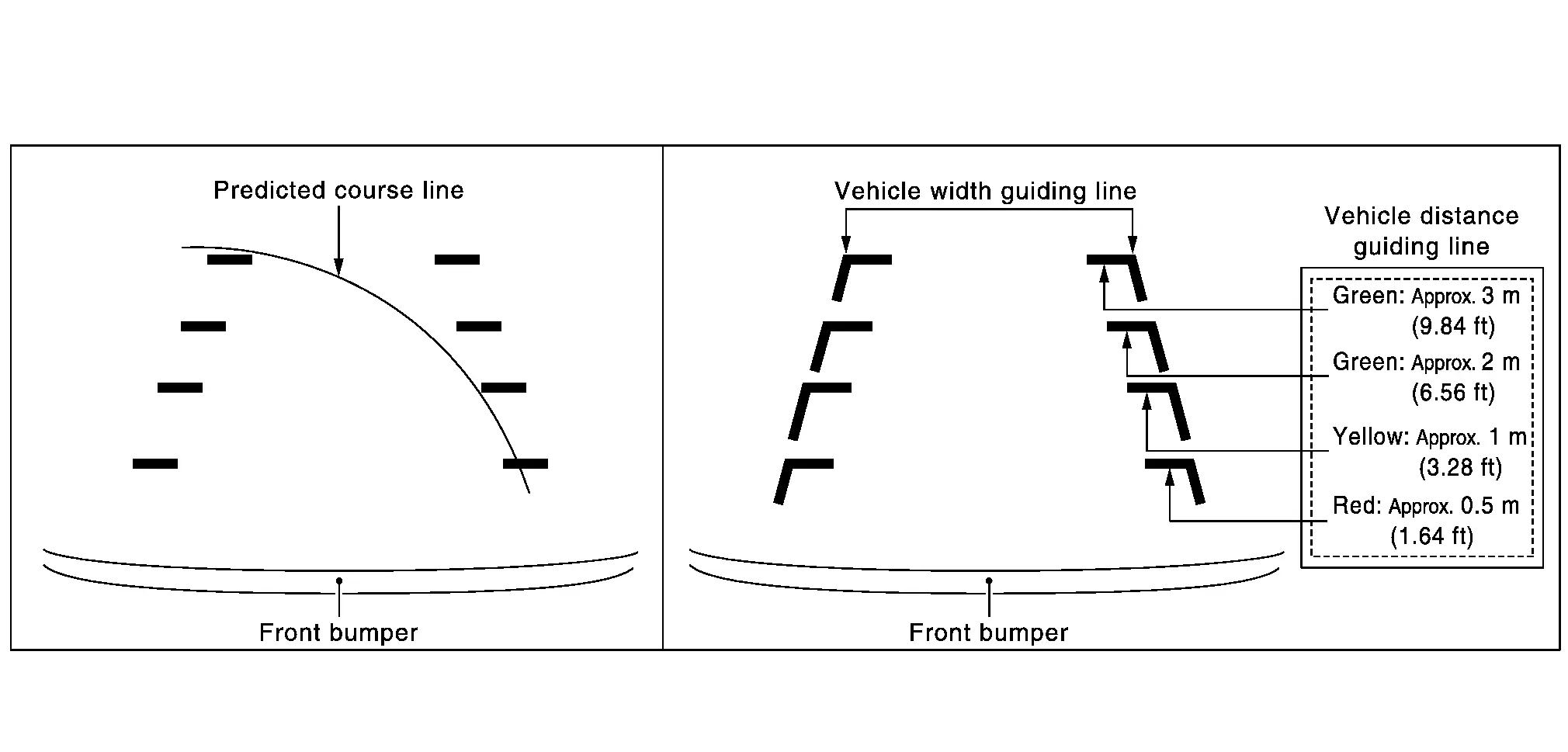
  • In front view and rear view, the Nissan Pathfinder vehicle width, distance lines and predictive course lines are superimposed and displayed. In front-side view, the Nissan Pathfinder vehicle distance guiding line and vehicle width guiding line are displayed.

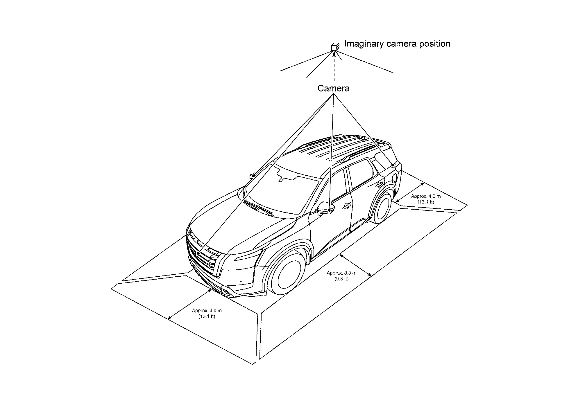
  • The Birds-Eye view converts the images from 4 cameras into the overhead view and displays the status of the Nissan Pathfinder vehicle on display. The vehicle icon and sonar indicator that are displayed on the Birds-Eye view display are rendered by around view monitor control unit.

  • Moving Object Detection (MOD) is adopted that detects moving objects according to camera image and notifies the detection result to the driver.

  • Front/rear wide view function is adopted. Visibility for the left and right that contains invisible area is improved.

AROUND VIEW MONITOR SCREEN

  • Around view monitor combines and displays the travel direction view and “Birds-Eye view”, “Front-Side view” and then it displays the sonar indicator on the “Birds-Eye view”, “Front-Side view”, "Front wide view" and “Rear wide view”.

  • Around view monitor control unit renders the view icon, warning message on display.

Screen Constitution (Models with Invisible Area)
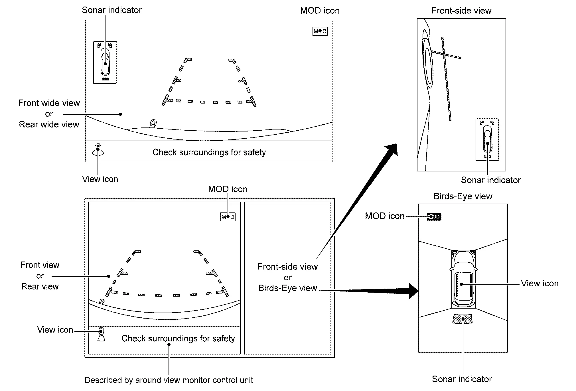
Screen Constitution (Models without Invisible Area)
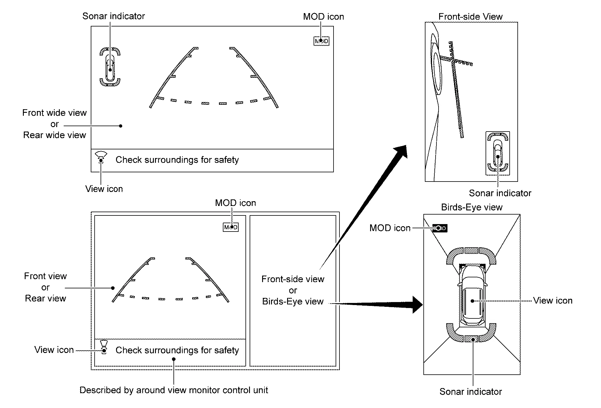
OPERATION DESCRIPTION

Around view monitor screen transition

  • Around view monitor is displayed on the display when “CAMERA” switch is pressed, when shifting position is reverse, or when an obstacle is detected by sonar system.

  • Birds-Eye view, Front-side view, and front/rear wide view can be switched by “CAMERA” switch, while around view monitor is displayed.

  • While shift position is other than reverse, around view monitor is cancelled when approximately 3 minutes are passed after “CAMERA” switch is pressed, or when Nissan Pathfinder vehicle speed is approximately 10 km/h or more. The screen returns to the screen before displaying around view monitor.

  • Setting of Moving Object Detection (MOD) and sonar can be switched ON/OFF by combination meter.

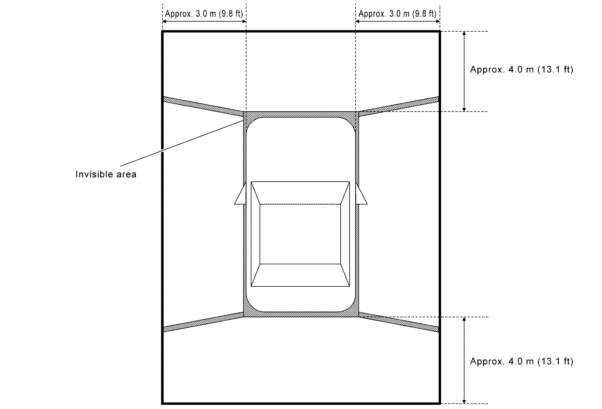
  • In Birds-Eye view, an enhanced boundary is displayed on the image indicating the invisible area and clearly indicating the boundary of the 4 cameras. The invisible area is displayed in yellow when Birds-Eye view is displayed after the ignition switch is turned ON. (Models with invisible area)

  • In D position, front sonar can detect an obstacle while camera image is not displayed on AV control unit. Screen is switched to camera image when an obstacle is detected.

  • When “CAMERA” switch is pressed, it receives camera switch signal from AV control unit via CAN communication.

  • When around view monitor control unit receives camera switch signal, around view monitor control unit reads the image signal from each camera.

  • When around view monitor control unit receives reverse signal, while shift position is R position, around view monitor control unit reads image signal from each camera by LVDS.

  • When around view monitor control unit reads image signal from each camera, it cuts out the required screen for each view, superimposes camera image, Nissan Pathfinder vehicle icon, guiding lines, predicted course line, “MOD” icon, and sonar indicator, and then outputs them to AV control unit by LVDS.

Front View

  • The front view image is from the front camera.

  • When the selector lever is in any position other than the reverse position, the front view is displayed by pressing the “CAMERA” switch. It improves the visibility of obstacles in front of the Nissan Pathfinder vehicle and helps driving by the images displayed from Birds-Eye view and Front-Side view. The front wide view function allows the display of an image with an approximately 180° horizontal angle.

  • Display the Nissan Pathfinder vehicle width guiding line and vehicle distance guiding line in front view and display the predictive course line according to the steering angle.

  • If the steering angle is within approximately 90 degrees, the predictive course lines on the left/right side are displayed. If the steering angle is exceeding approximately 90 degrees, only the predictive course line on the outside (in the opposite side of steering direction) is displayed.

  • Around view monitor control unit receives the steering angle signal from ABS actuator and electric unit (control unit) via CAN communication.

  • Around view monitor control unit controls the direction of the predictive course line according to the steering sensor angle signal.

Front view guiding lines
Rear View

  • The rear view image is from the rear camera.

  • When the selector lever is in the reverse position, the rear view is displayed. Backing and parking are improved by the images from Birds-Eye view and Front-Side view. The rear wide view function allows the display of an image with an approximately 180° horizontal angle.

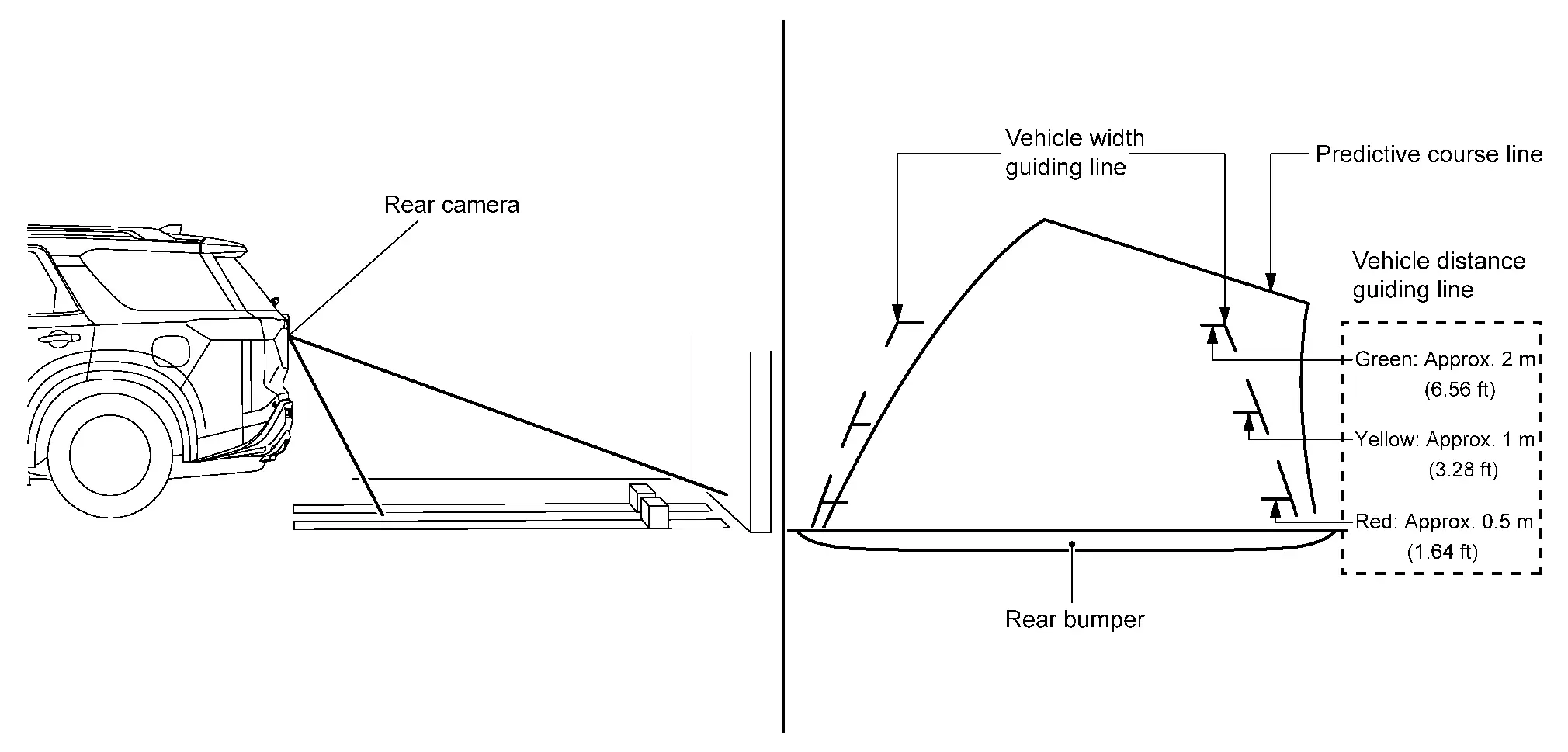
  • Display the Nissan Pathfinder vehicle width guiding line and vehicle distance guiding line in rear view and display the predictive course line according to the steering angle.

  • The predictive course line is not displayed at the steering neutral position.

  • Around view monitor control unit receives the steering angle signal from ABS actuator and electric unit (control unit) via CAN communication.

  • Around view monitor control unit controls the direction and distance of predictive course line according to the steering angle sensor signal.

    Rear view guiding lines
Front-side View

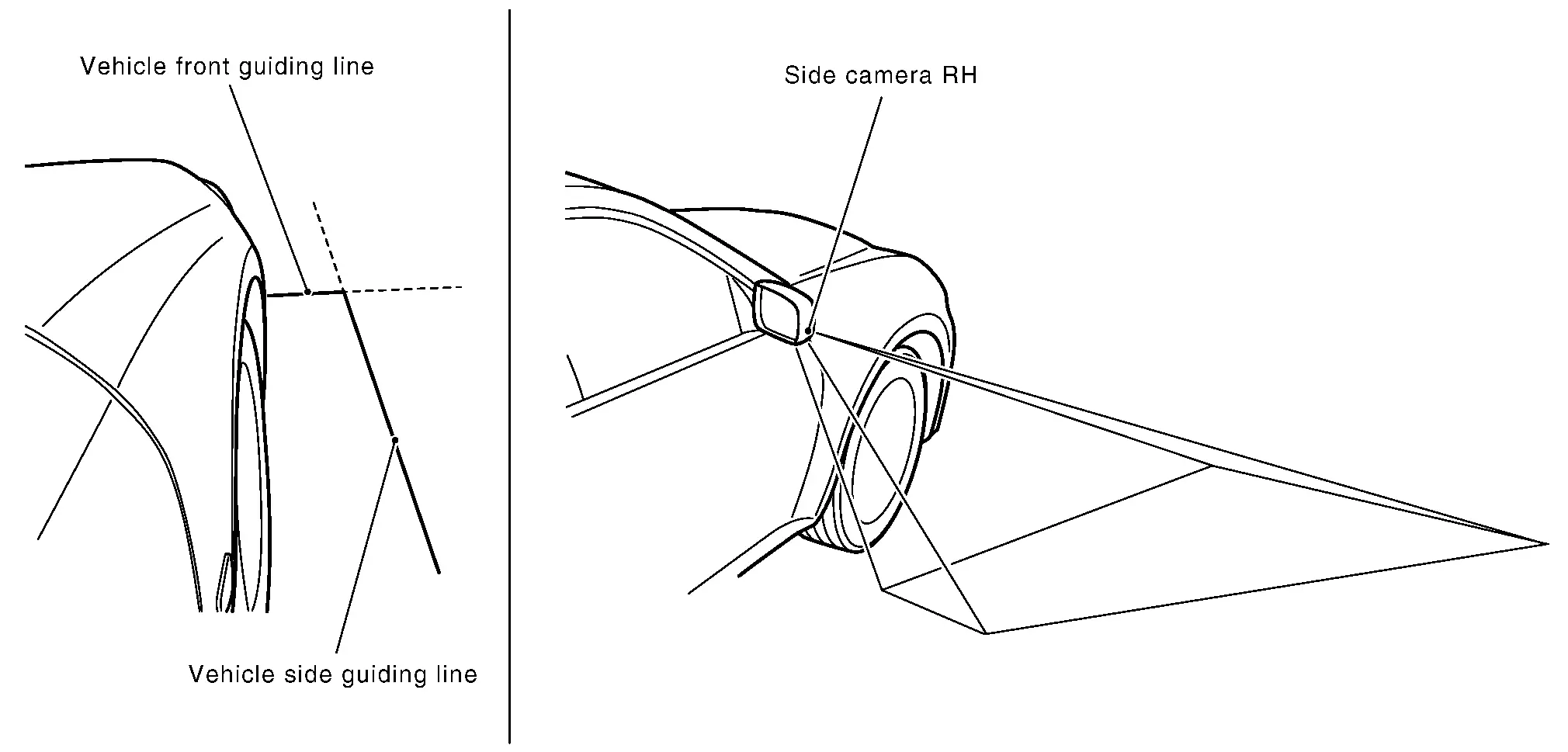
  • The front-side view image is from the side camera RH.

  • In front-side view, display the Nissan Pathfinder vehicle distance guiding line and vehicle width guiding line.

Front-side view area and guiding line
Birds-eye View

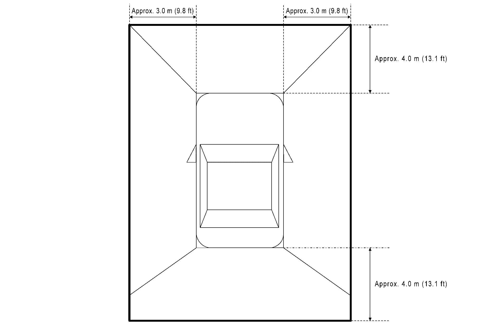
  • The image from the 4 cameras is cut out and converted into the overhead view, and the surroundings of the Nissan Pathfinder vehicle is displayed in birds-eye view.

  • In Birds-Eye view, the invisible area is displayed on the image to specify the boundary of the 4 cameras. (Models with invisible area)

Birds-Eye view display image
Birds-Eye view display area (Models with Invisible Area)
Birds-Eye view display area (Models without Invisible Area)
Moving Object Detection (MOD)

  • Moving Object Detection (MOD) is a function that notifies the driver of the presence of moving objects in the area around the Nissan Pathfinder vehicle. MOD detects moving objects from camera image, illuminates frame of view in yellow whenever “MOD” icon is displayed in green, and sounds buzzer.

  • MOD detects moving objects while camera image is displayed on AV control unit.

  • Around view monitor control unit performs the following process when moving objects are detected.

    • Superimposes yellow frame line on camera image signal and outputs them to AV control unit by LVDS.

    • Transmits MOD beep sound output request signal to combination meter via CAN communication.

    • Combination meter that receives the MOD beep sound output request signal from around view monitor control unit, and outputs buzzer drive signal to buzzer.

  • Around view monitor control unit detects moving objects from camera image according to an image recognition method called optical flow.

  • MOD does not detect a background as a moving object when the Nissan Pathfinder vehicle moves (when whole screen moves), but detects a moving object when an actual moving object is displayed on screen.

  • MOD can be set to permanent OFF by the following operation.

    • Permanent OFF: Settings can be performed on the information display of the combination meter.

  • Color of “MOD” icon indicates whether or not MOD is operative. “MOD” icon is displayed as shown in the following table. when MOD is operative, “MOD” icon is displayed in green. when MOD is not operative, “MOD” icon is displayed in gray. MOD icon is not displayed when MOD is OFF by “Settings”.

    ViewShift position
    P or N positionD positionR position
    “MOD” icon display
    Birds-Eye view and rear view Birds-Eye view — — Gray
    Rear view Green
    Birds-Eye view and front view Birds-Eye view Green Gray —
    Front view Gray Green
    Side view and rear view Side view — — ×
    Rear view Green
    Side view and front view Side view × × —
    Front view Gray Green
    Rear wide view — — Green
    Front wide view Gray Green —

    ×: Icon is not displayed.

    —: View is not displayed in each shift position (P or N position, D position and R position).

  • MOD illuminates frame of view in yellow and sounds buzzer, when any of the conditions in the following table are satisfied.

    Operation ConditionView where MOD is operative
    Shift positionNissan Pathfinder Vehicle speed
    P or N position 0 km/h Birds-Eye view
    D position 0 km/h or more - less than 8 km/h
    • Front view

    • Front wide view

    R position 0 km/h or more - less than 8 km/h
    • Rear view

    • Rear wide view

  • MOD does not operate or stops operation when any of the conditions in the following table are satisfied.

    Operation stop conditionNote
    Door open
    • MOD does not stop operation for front view and front wide view.

    • Operation stops for rear view and rear wide view while back door is open.

    • Operation stops for Birds-Eye view when any door is open.

    Door mirror expanding/retracting Expanding/retracting status of door mirror is judged according to operation signal of door mirror motor transmitted from door mirror (driver side) to around view monitor control unit.

CAMERA ASSISTANCE SONAR FUNCTION

  • Sonar sensors are installed on front and rear bumpers. When an obstacle is detected while Intelligent Around View Monitor is displayed, a sonar indicator display and buzzer sound notify the driver of the proximity of an obstacle. When an obstacle is detected while Intelligent Around View Monitor is not displayed, Intelligent Around View Monitor screen is displayed automatically, and then notification is similar as while Intelligent Around View Monitor is displayed.

  • Approaching distance between bumper and obstacle is displayed in 3 stages according to the color of the sonar indicator in display and blinking cycle of indicator.

  • Warning by buzzer sound notifies distance to obstacle according to a 3-stage cycle.

MAC(Message Authentication Code)

MAC (Message Authentication Code) is a function that prevents unauthorized communication from other than the ECU with MAC function by secure authentication communication. Around view monitor control unit can write a MAC key required for communication between the ECUs and perform MAC diagnosis.

Diagnosis System (around View Monitor Control Unit) Nissan Pathfinder Fifth generation

CONSULT Function

CONSULT FUNCTIONS

CONSULT performs the following functions via the communication with the around view monitor control unit.

Diagnosis modeDescription
Self Diagnostic Result Around view monitor control unit and AV communication circuit connection diagnosis is performed. Current and previous malfunctions are displayed collectively.
Data Monitor Diagnosis of Nissan Pathfinder vehicle signal that is received by around view monitor control unit can be performed.
Work support
  • Display of predicted course line can be switched to ON/OFF.

  • Correction of turning radius display can be performed.

  • MOD function can be switched to ON/OFF.

  • Calibration and initialization of each camera can be performed.

  • Fine tuning of Birds-Eye view can be performed.

  • MAC KEY can be writing.

ECU Identification Around view monitor control unit part number, software version, and hardware version can be identified.
Configuration* Writes the Nissan Pathfinder vehicle specification when replacing around view monitor control unit.
MAC Diagnosis*

Display MAC diagnosis result divided into the following two inspection priorities.

  • Inspection Priority 1: Root cause

  • Inspection Priority 2

*: Displays when performing "Diagnosis (All System)".

SELF DIAGNOSTIC RESULT

Refer to DTC Index.

  • In CONSULT self-diagnosis, self-diagnosis results and error history are displayed collectively.

  • The current malfunction indicates “CRNT”. The past malfunction indicates “PAST”.

Freeze Frame Data (FFD)

The following vehicle status is recorded when DTC is detected and is displayed on CONSULT.

Item name [Unit]Display content

ODO/TRIP METER

[km]
Total driving distance (odometer value) upon DTC detection is displayed.

DATA MONITOR

  • Displays the status of the following vehicle signals inputted into the around view monitor control unit.

  • For each signal, actual signal can be compared with the condition recognized on the system.

    Display ItemRemarks

    REVERSE SIGNAL

    [On/Off]
    Receiving status of shift position (reverse) signal received from TCM is displayed by ON/OFF.

    CAMERA SWITCH SIGNAL

    [On/Off]
    Receiving status of camera switch signal received from AV control unit is displayed by ON/OFF.

    CAMERA OFF SIGNAL

    [On/Off]
    Receiving status of camera OFF signal received from AVcontrol unit is displayed by ON/OFF.

    REAR CAMERA IMAGE SIGNAL

    [OK/NG]
    Input status of rear view camera image signal is displayed by OK/NG in real time.

    R-CAMERA COMM STATUS

    [OK/NG]
    Communication status with rear camera is displayed by OK/NG in real time.

    R-CAMERA COMM LINE

    [OK/NG]
    Status of communication line with rear camera is displayed by OK/NG in real time.

    F-CAMERA IMAGE SIGNAL

    [OK/NG]
    Input status of front view camera image signal is displayed by OK/NG in real time.

    F-CAMERA COMM STATUS

    [OK/NG]
    Communication status with front camera is displayed by OK/NG in real time.

    F-CAMERA COMM LINE

    [OK/NG]
    Status of communication line with front camera is displayed by OK/NG in real time.

    Left camera image signal

    [OK/NG]
    Input status of side camera LH image signal is displayed by OK/NG in real time.

    Left camera comm status

    [OK/NG]
    Communication status with side camera LH is displayed by OK/NG in real time.

    Left camera line

    [OK/NG]
    Status of communication line with side camera LH is displayed by OK/NG in real time.

    Right camera image signal

    [OK/NG]
    Input status of side camera RH image signal is displayed by OK/NG in real time.

    Right camera comm status

    [OK/NG]
    Communication status with side camera RH is displayed by OK/NG in real time.

    Right camera line

    [OK/NG]
    Status of communication line with side camera RH is displayed by OK/NG in real time.

    FOLDING MOTOR VOLT 1

    [On/Off]
    Receiving status of mirror fold position (open) signal received from door mirror RH is displayed by ON/OFF.

    FOLDING MOTOR VOLT 2

    [On/Off]
    Receiving status of mirror fold position (close) signal received from door mirror RH is displayed by ON/OFF.

    Image output

    [On/Off]
    Display the image signal transmission status by ON / OFF in real time.
    Power supply state Display the value of around view monitor control unit power supply.

    Nissan Pathfinder Vehicle speed

    [KPH]
    Display the value of vehicle speed signal.

WORK SUPPORT

Work support itemsDescription
MAC KEY writing Write MAC key to around view monitor control unit.
PREDICTIVE COURSE LINE DISPLAY
tire diameter correction
MOD function Select ON/OFF for MOD function.
INITIALIZE CAMERA IMAGE CALIBRATION

The calibration can be initialized to factory shipment condition.

CALIBRATING CAMERA IMAGE (FRONT CAMERA)

Performs the calibration of front camera.

CALIBRATING CAMERA IMAGE (PASS-SIDE CAMERA)

Performs the calibration of side camera RH.

CALIBRATING CAMERA IMAGE (DR-SIDE CAMERA)

Performs the calibration of side camera LH.

CALIBRATING CAMERA IMAGE (REAR CAMERA)

Performs the calibration of rear camera.

FINE TUNING OF BIRDS-EYE VIEW

The confirmation and adjustment of the difference between each camera can be performed.

The fine adjustment function of camera calibration can check and adjust the difference between each camera.

ECU IDENTIFICATION

Around view monitor control unit part number, software version, and hardware version can be identified.

CONFIGURATION

Writes the vehicle specification when replacing around view monitor control unit.