Charging System - System Description
- Component Parts. Charging System
- Charging System
- Power Generation Voltage Variable Control System
- Warning/indicator/chime List
Component Parts. Charging System Nissan Pathfinder 2026
Component Parts Location
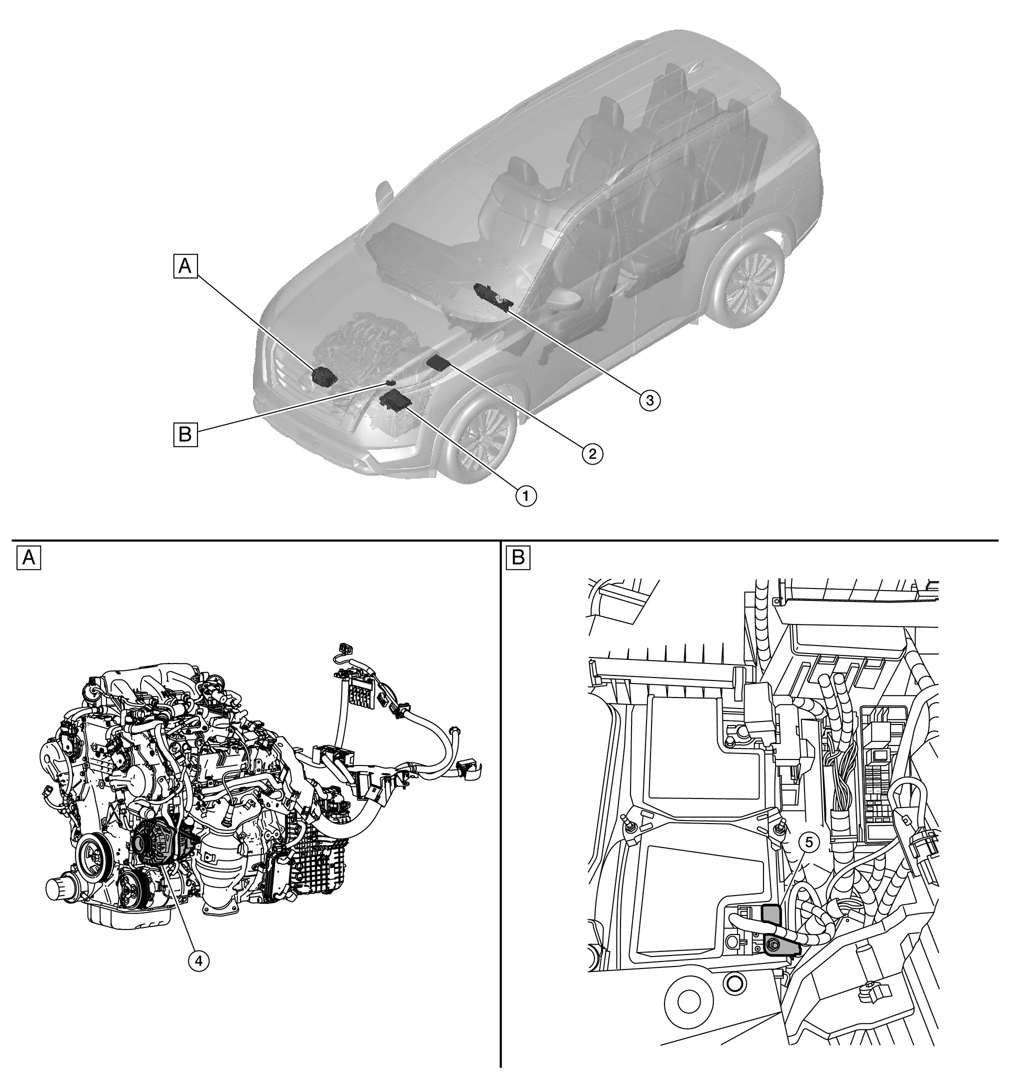
| A. | View with engine and transmission removed | B. | Engine room left side |
| No. | Component | Function |
|---|---|---|
| 1. | ECM (Engine Control Module) |
ECM transmits the received generator voltage request signal to the generator via LIN communication signal. Refer to Component Parts Location for detailed component location. |
| 2. | IPDM E/R (Intelligent Power Distribution Module Engine Room) |
IPDM E/R sends the generator voltage request signal to ECM via CAN communication. Refer to System Description. |
| 3. | Combination meter | The control module inside generator warning function activates to illuminate the charge warning lamp if any of the following symptoms occur while generator is operating:
|
| 4. | Generator | Refer to Generator. |
| 5. | Battery current sensor | Refer to Battery Current Sensor. |
Generator
The generator is mounted on the front of the engine, near the top.
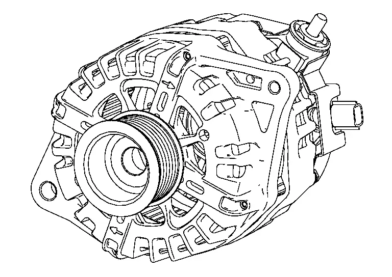
The generator provides DC voltage to operate the Nissan Pathfinder vehicle's electrical system and to keep the battery charged.
Battery Current Sensor
The battery current sensor is installed to the battery negative cable.
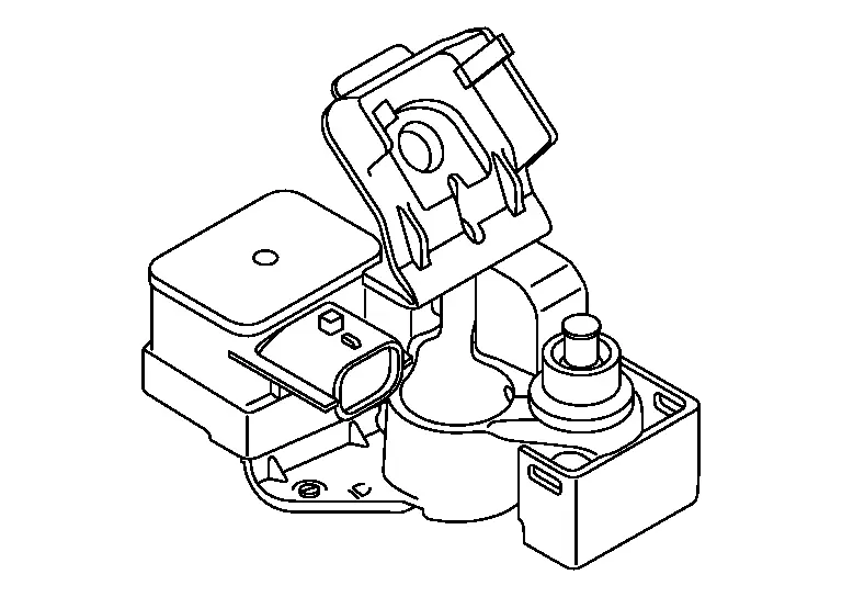
The sensor measures the charging/discharging current of the battery.
Charging System Nissan Pathfinder
System Diagram
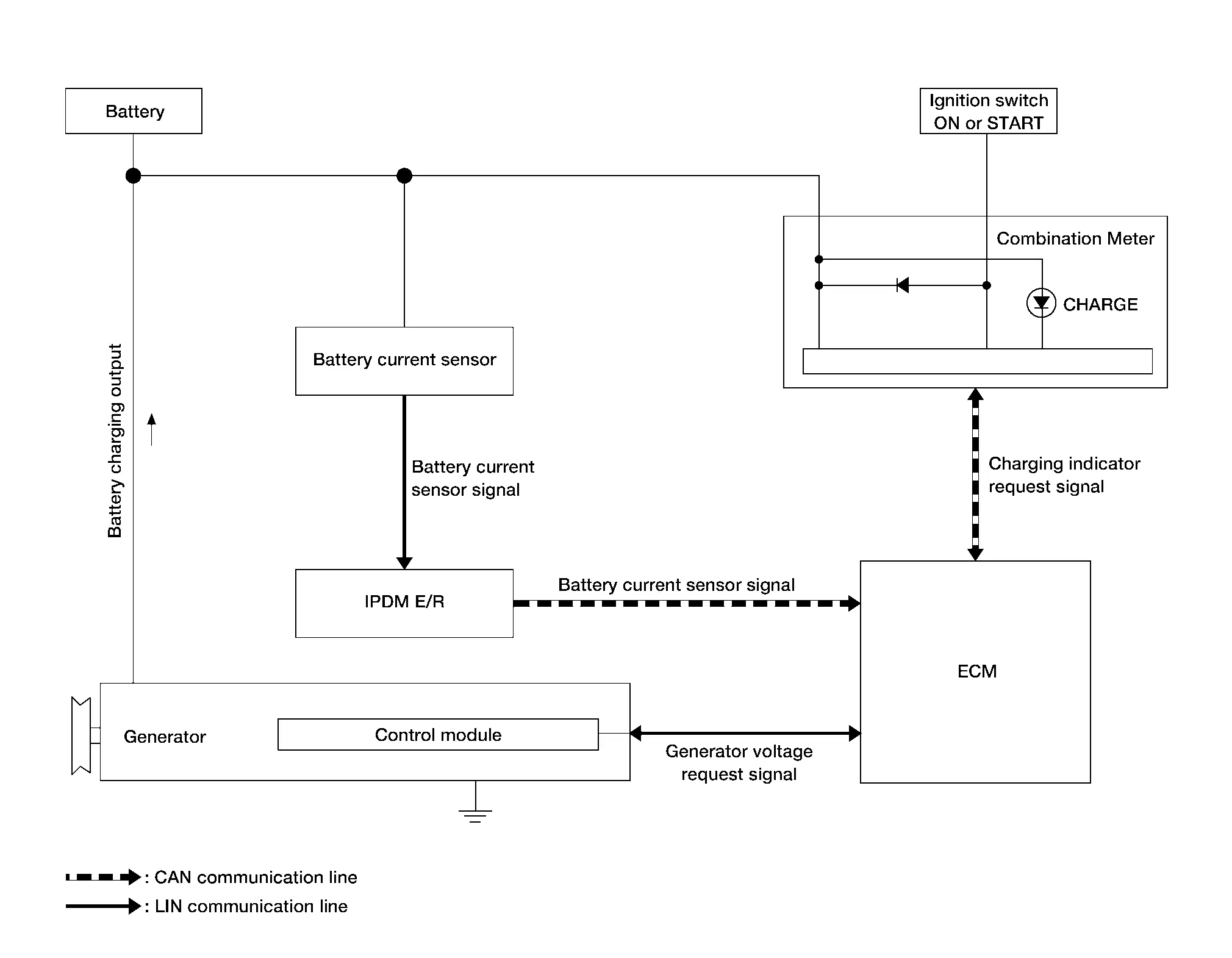
System Description
INPUT SIGNAL AND OUTPUT SIGNAL CHART
| Component | Signal |
|---|---|
| IPDM E/R | Generator voltage request signal via CAN communication |
| Generator | Generator voltage request signal (via LIN communication) |
| Battery current sensor | Battery current signal (via LIN communication) |
| Combination meter | Charging indicator request signal |
SYSTEM DESCRIPTION
The battery current sensor measures the charging/discharging current of the battery.
The generator provides DC voltage to operate the Nissan Pathfinder vehicle's electrical system and to keep the battery charged. The voltage output is controlled by the ECM.
Control module inside the generator controls the power generation voltage based on the received generator voltage request signal.
Power Generation Voltage Variable Control System Nissan Pathfinder 5th Gen
System Description
SYSTEM DESCRIPTION
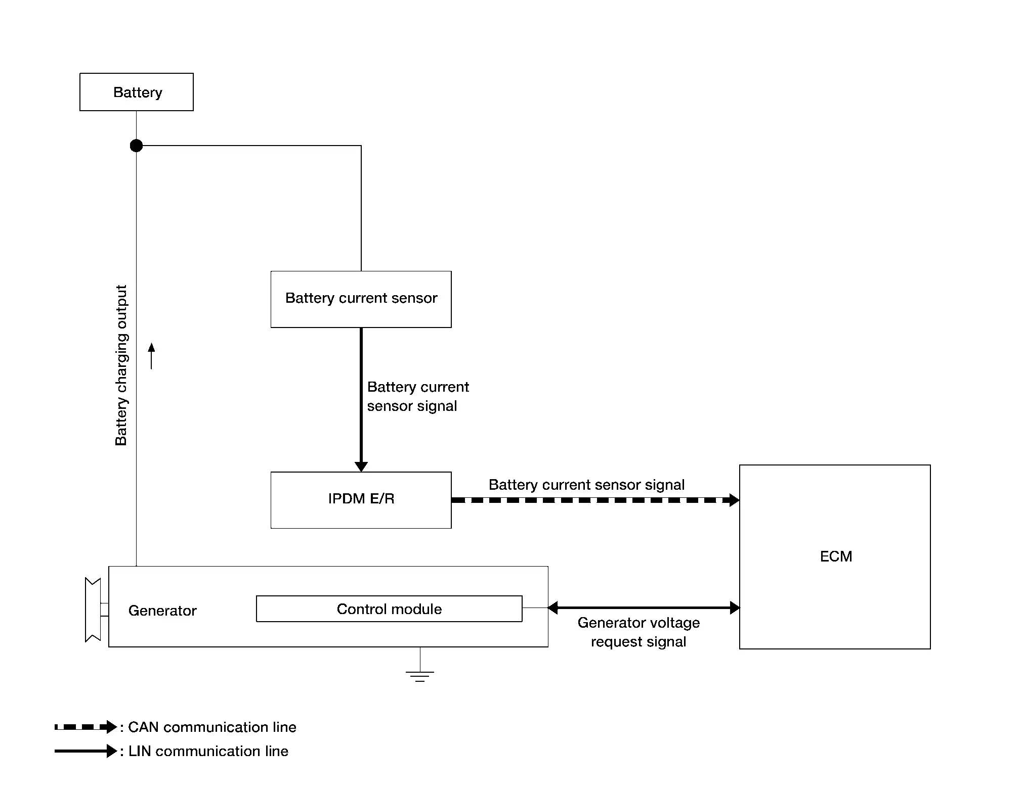
INPUT SIGNAL AND OUTPUT SIGNAL CHART
Multiple signals are transmitted from the following units to the ECM:
| Component | Signal |
|---|---|
| IPDM E/R | Generator voltage request signal (via CAN communication) |
| Generator | Generator voltage request signal (via LIN communication) |
| Battery current sensor | Battery current signal (via LIN communication) |
SYSTEM DESCRIPTION
Battery current sensor measures the charging/discharging current of the battery.
ECM judges battery condition according to the charging/discharging current of the battery.
ECM transmits generator voltage request signal to generator via LIN communication.
Control module inside generator controls the power generation voltage based on the received generator voltage request signal.
Generator includes a self-diagnosis function and transmits the diagnosis result to ECM via LIN communication when detecting any malfunction.
Warning/indicator/chime List Nissan Pathfinder 2026
Warning Lamps/Indicator Lamps
| Item | Design | Reference |
|---|---|---|
| Charge warning lamp |  |
For layout, refer to Design (full TFT meter) or Design (7 inch information display meter). |
| For function, refer to System Description. |