Security Control System - Dtc/circuit Diagnosis
- P161d-00 Immobilizer
- P161e-00 Immobilizer
- P161f-00 Immobilizer
- B2c20-12 Starter Control Relay
- B2c20-23 Starter Control Relay
- B2f70-01 Stop Lamp
- B2f71-23 Stop Lamp
- B2f72-23 Stop Lamp
- B2080 Power Switch
- B2033-4a Dongle Ng
- B2042-4a Electric Shift Authentication Fail
- B2043-4a Electric Shift Id Discord
- B2070-68 Key Registration
- B2090-14 Nats Antenna Amp.
- Hood Switch
- Horn Function
- Starter Cut Relay
- Stop Lamp Switch
- Brake Pedal Position Switch
P161d-00 Immobilizer Nissan Pathfinder 5th Gen
DTC Description
DTC DETECTION LOGIC
| DTC No. | CONSULT screen items (Trouble diagnosis content) | DTC detecting condition | |
|---|---|---|---|
| P161D-00 | IMMOBILIZER (Immobilizer) |
Diagnosis condition | Ignition switch ON |
| Signal (terminal) | — | ||
| Threshold | When key registration has not been completed normally after replacing Intelligent Key unit. | ||
| Diagnosis delay time | 1 second or less | ||
POSSIBLE CAUSE
Improper key registration operation
EPS control unit
Intelligent Key unit
FAIL-SAFE
—
CONFIRMATION PROCEDURE
PERFORM DTC CONFIRMATION PROCEDURE
 CONSULT
Ignition switch ON.
Select “Self Diagnostic Result” mode of “ENGINE”.
Is the DTC detected?
YES>>Refer to DTC Diagnosis Procedure.
NO>>To check malfunction symptom before repair: Refer to Intermittent Incident.
NO>>Confirmation after repair: Inspection End.
DTC Diagnosis Procedure
CHECK DTC PRIORITY OF INTELLIGENT KEY UNIT
If DTC P161D-00 is displayed with DTC B2033-4A, first perform the trouble diagnosis for DTC B2033-4A.
Is DTC B2033-4A detected?
YES>>Perform diagnosis of applicable. DTC B2033-4A: Refer to DTC Description.
NO>>GO TO 2.
INTELLIGENT KEY REGISTRATION
 CONSULT
Perform registration of all Intelligent Keys.
For registration procedures, refer to CONSULT immobilizer mode and follow the on-screen instructions.
Erase DTC.
Perform DTC confirmation procedure for DTC P161D-00. Refer to DTC Description.
Is DTC P161D-00 detected?
YES>>GO TO 3.
NO>>Inspection End.
REPLACE INTELLIGENT KEY UNIT
Replace Intelligent Key unit. Refer to Removal and Installation.
Erase DTC.
Perform DTC confirmation procedure for DTC P161D-00. Refer to DTC Description.
Check that the DTC is not detected.
Inspection End.
P161e-00 Immobilizer Nissan Pathfinder SUV
DTC Description
DTC DETECTION LOGIC
| DTC No. | CONSULT screen items (Trouble diagnosis content) | DTC detecting condition | |
|---|---|---|---|
| P161E-00 | IMMOBILIZER (Immobilizer) |
Diagnosis condition | Ignition switch ON |
| Signal (terminal) | — | ||
| Threshold | When CONSULT is not used during ECM replacement. | ||
| Diagnosis delay time | 1 second or less | ||
POSSIBLE CAUSE
Intelligent Key unit
ECM
FAIL-SAFE
Inhibit engine cranking
CONFIRMATION PROCEDURE
PERFORM DTC CONFIRMATION PROCEDURE
 CONSULT
Ignition switch ON.
Select “Self Diagnostic Result” mode of “ENGINE”.
Is the DTC detected?
YES>>Refer to DTC Diagnosis Procedure.
NO>>To check malfunction symptom before repair: Refer to Intermittent Incident.
NO>>Confirmation after repair: Inspection End.
DTC Diagnosis Procedure
ECM REGISTRATION
 CONSULT
Register ECM.
Is the DTC detected?
YES>>GO TO 2.
NO>>Inspection End.
REPLACE INTELLIGENT KEY UNIT
Replace Intelligent Key unit. Refer to Removal and Installation.
Is the DTC detected?
YES>>GO TO 3.
NO>>Inspection End.
REPLACE ECM
Replace ECM. Refer to Removal and Installation.
>>Inspection End.
P161f-00 Immobilizer Nissan Pathfinder 2022
DTC Description
DTC DETECTION LOGIC
| DTC No. | CONSULT screen items (Trouble diagnosis content) | DTC detecting condition | |
|---|---|---|---|
| P161F-00 | IMMOBILIZER (Immobilizer) |
Diagnosis condition | Ignition switch ON |
| Signal (terminal) | — | ||
| Threshold | When Intelligent Key unit detects an immobilizer malfunction and engine start is prohibited. | ||
| Diagnosis delay time | 1 second or less | ||
POSSIBLE CAUSE
ECM
FAIL-SAFE
Inhibit engine cranking
CONFIRMATION PROCEDURE
PERFORM DTC CONFIRMATION PROCEDURE
 CONSULT
Ignition switch ON.
Select “Self Diagnostic Result” mode of “ENGINE”.
Is the DTC detected?
YES>>Refer to DTC Diagnosis Procedure.
NO>>To check malfunction symptom before repair: Refer to Intermittent Incident.
NO>>Confirmation after repair: Inspection End.
DTC Diagnosis Procedure
REPLACE ECM
Replace ECM. Refer to Removal and Installation.
>>Inspection End.
B2c20-12 Starter Control Relay Nissan Pathfinder 2026
DTC Description
DTC DETECTION LOGIC
| DTC No. | CONSULT screen items (Trouble diagnosis content) | DTC detecting condition | |
|---|---|---|---|
| B2C20-12 | Starter control relay (Starter control relay) |
Diagnosis condition | Ignition switch ON |
| Signal (terminal) | Starter cut relay signal | ||
| Threshold | When BCM detects starter cut relay circuit is short to buttery | ||
| Diagnosis delay time | 1 second or less | ||
POSSIBLE CAUSE
Harness or connectors
(Starter cut relay circuit is short to battery)
Starter cut relay
FAIL-SAFE
—
CONFIRMATION PROCEDURE
PERFORM DTC CONFIRMATION PROCEDURE
 CONSULT
Press ignition switch under the following conditions and wait 1 second or more.
Selector lever: In the P position.
Brake pedal: Depressed.
Select “Self Diagnostic Result” mode of “BCM”.
Is the DTC detected?
YES>>Refer to DTC Diagnosis Procedure.
NO>>To check malfunction symptom before repair: Refer to Intermittent Incident.
NO>>Confirmation after repair: Inspection End.
DTC Diagnosis Procedure
CHECK STARTER CUT RELAY INPUT SIGNAL
Check voltage between BCM harness connector and ground.
| (+) | (-) | Condition | Voltage (Approx.) | |
|---|---|---|---|---|
| BCM | ||||
| Connector | Terminal | |||
| M80 | 123 | Ground | Other than following | Battery voltage |
| At engine cranking | 0 V | |||
Is the inspection result normal?
YES>>Inspection End.
NO>>GO TO 2.
CHECK STARTER CUT RELAY INPUT SIGNAL CIRCUIT
Ignition switch OFF.
Disconnect BCM connector and starter cut relay connector.
Check continuity between BCM harness connector and starter cut relay harness connector.
BCM Starter cut relay Continuity Connector Terminal Connector Terminal M80 123 E36 8 Yes Check continuity between BCM harness connector and ground.
BCM (–) Continuity Connector Terminal M80 123 Ground No
Is the inspection result normal?
YES>>GO TO 3.
NO>>Repair or replace harness.
CHECK STARTER CUT RELAY
Check starter cut relay. Refer to Component Inspection.
Is the inspection result normal?
YES>>Inspection End.
NO>>Replace starter cut relay.
B2c20-23 Starter Control Relay Nissan Pathfinder
DTC Description
DTC DETECTION LOGIC
| DTC No. | CONSULT screen items (Trouble diagnosis content) | DTC detecting condition | |
|---|---|---|---|
| B2C20-23 | Starter control relay (Starter control relay) |
Diagnosis condition | Ignition switch ON |
| Signal (terminal) |
|
||
| Threshold | When the starter cut relay status signal transmitted from IPDM E/R via CAN communication is OFF after even though BCM is operating the starter cut relay ON output. | ||
| Diagnosis delay time | 1 second or less | ||
POSSIBLE CAUSE
Harness or connectors
(The CAN communication line is open or shorted)
Harness or connectors
(Starter cut relay circuit is short to ground or open)
Starter cut relay
FAIL-SAFE
—
CONFIRMATION PROCEDURE
PERFORM DTC CONFIRMATION PROCEDURE
 CONSULT
Press ignition switch under the following conditions and wait 1 second or more.
Selector lever: In the P position.
Brake pedal: Depressed.
Select “Self Diagnostic Result” mode of “BCM”.
Is the DTC detected?
YES>>Refer to DTC Diagnosis Procedure.
NO>>To check malfunction symptom before repair: Refer to Intermittent Incident.
NO>>Confirmation after repair: Inspection End.
DTC Diagnosis Procedure
CHECK STARTER CUT RELAY INPUT SIGNAL
Check voltage between BCM harness connector and ground.
| (+) | (-) | Condition | Voltage (Approx.) | |
|---|---|---|---|---|
| BCM | ||||
| Connector | Terminal | |||
| M80 | 123 | Ground | Other than following | Battery voltage |
| At engine cranking | 0 V | |||
Is the inspection result normal?
YES>>GO TO 4.
NO>>GO TO 2.
CHECK STARTER CUT RELAY INPUT SIGNAL CIRCUIT
Ignition switch OFF.
Disconnect BCM connector and starter cut relay connector.
Check continuity between BCM harness connector and starter cut relay harness connector.
BCM Starter cut relay Continuity Connector Terminal Connector Terminal M80 123 E36 8 Yes Check continuity between BCM harness connector and ground.
BCM — Continuity Connector Terminal M80 123 Ground No
Is the inspection result normal?
YES>>GO TO 3.
NO>>Repair or replace harness.
CHECK FUSIBLE LINK
Check that the following fusible link is not blown (open).
| Signal name | Fusible link | Capacity |
|---|---|---|
| Battery power supply | R | 30 A |
Is the fusible link blown (open)?
YES>>Replace the blown (open) fusible link after repairing the affected circuit if a fusible link is blown (open).
NO>>GO TO 6.
CHECK STARTER CUT RELAY OUTPUT SIGNAL
Check voltage between IPDM E/R harness connector and ground.
| (+) | (-) | Condition | Voltage (Approx.) | |
|---|---|---|---|---|
| IPDM E/R | ||||
| Connector | Terminal | |||
| E77 | 86 | Ground | Other than at engine cranking | Less than 4 V (IPDM E/R always outputs the voltage to detect the ON/ OFF state of starter cut relay) |
| At engine cranking | Battery voltage | |||
Is the inspection result normal?
YES>>Inspection End.
NO>>GO TO 5.
CHECK STARTER CUT RELAY OUTPUT SIGNAL CIRCUIT
Ignition switch OFF.
Disconnect IPDM E/R connector and starter cut relay connector.
Check continuity between IPDM E/R harness connector and starter cut relay harness connector.
IPDM E/R Starter cut relay Continuity Connector Terminal Connector Terminal E77 86 E36 6 Yes Check continuity between IPDM E/R harness connector and ground.
IPDM E/R — Continuity Connector Terminal E77 86 Ground No
Is the inspection result normal?
YES>>GO TO 6.
NO>>Repair or replace harness.
CHECK STARTER CUT RELAY
Check starter cut relay. Refer to Component Inspection.
Is the inspection result normal?
YES>>Inspection End.
NO>>Replace starter cut relay.
B2f70-01 Stop Lamp Nissan Pathfinder 5th Gen
DTC Description
DTC DETECTION LOGIC
| DTC No. | CONSULT screen items (Trouble diagnosis content) | DTC detecting condition | |
|---|---|---|---|
| B2F70-01 | Stop lamp (Stop lamp) |
Diagnosis condition | When brake pedal is depressed |
| Signal (terminal) |
|
||
| Threshold | BCM makes a comparison between stop lamp switch 1 signal and stop lamp switch 2 signal. It judges from their values to detect the malfunctioning circuit 10 consecutive times | ||
| Diagnosis delay time | Depress brake pedal 10 times | ||
POSSIBLE CAUSE
Harness or connectors
(Stop lamp switch circuit is open or shorted)
Stop lamp switch
Fuse
FAIL-SAFE
—
CONFIRMATION PROCEDURE
PERFORM DTC CONFIRMATION PROCEDURE
 CONSULT
Depress brake pedal 10 times.
Ignition switch ON.
Check DTC in “Self Diagnostic Result” mode of “BCM”.
Is DTC detected?
YES>>Refer to DTC Diagnosis Procedure.
NO>>To check malfunction symptom before repair: Refer to Intermittent Incident.
NO>>Confirmation after repair: Inspection End.
DTC Diagnosis Procedure
CHECK BRAKE PEDAL POSITION SWITCH
 CONSULT
Select “Brake switch 1” and “Brake switch 2” in “Data Monitor” mode of “SIGNAL BUFFER” of “BCM”.
Check “Brake switch 1” and “Brake switch 2” indication under the following condition.
| Monitor item | Condition | Indication | |
|---|---|---|---|
| Brake switch 1 | Brake pedal | Depressed | Off |
| Not depressed | On | ||
| Brake switch 2 | Depressed | On | |
| Not depressed | Off | ||
Is the indication normal?
YES>>Brake pedal position switch is OK.
NO>>Brake switch 1: GO TO 2.
NO>>Brake switch 2: GO TO 7.
CHECK FUSE
Check that the following fuse is not blown (open).
| Signal name | Fuse No. | Capacity |
|---|---|---|
| Battery power supply | 32 | 10 A |
Is the fuse blown (open)?
YES>>Replace the blown (open) fuse after replacing the cause of blown (open).
NO>>GO TO 3.
CHECK BRAKE PEDAL POSITION SWITCH SIGNAL
Ignition switch OFF.
Disconnect BCM connector.
Ignition switch ON.
Check voltage between BCM harness connector and ground.
(+) (–) Condition Voltage
(Approx.)BCM Connector Terminal M80 111 Ground Brake pedal position switch 1 ON (brake pedal is not depressed) Battery voltage Brake pedal position switch 1 OFF (brake pedal is depressed) 0 V
Is the inspection normal?
YES>>Inspection End.
NO>>GO TO 4.
CHECK BRAKE PEDAL POSITION SWITCH POWER SUPPLY CIRCUIT
Ignition switch OFF.
Disconnect brake pedal position switch connector.
Ignition switch ON.
Check voltage between brake pedal position switch harness connector and ground.
(+) (–) Voltage
(Approx.)Brake pedal position switch Connector Terminal E76 1 Ground Battery voltage
Is the inspection result normal?
YES>>GO TO 5.
NO>>Check harness for open or short between brake pedal position switch and fuse.
CHECK BRAKE PEDAL POSITION SWITCH SIGNAL CIRCUIT
Ignition switch OFF.
Check continuity between brake pedal position switch harness connector and BCM harness connector.
Brake pedal position switch BCM Continuity Connector Terminal Connector Terminal E76 2 M80 111 Yes Check continuity between brake pedal position switch harness connector and ground.
Brake pedal position switch (–) Continuity Connector Terminal E76 2 Ground No
Is the inspection result normal?
YES>>GO TO 6.
NO>>Repair or replace harness.
CHECK BRAKE PEDAL POSITION SWITCH
Refer to Component Inspection.
Is the inspection result normal?
YES>>Inspection End.
NO>>Replace brake pedal position switch. Refer to Exploded View.
CHECK FUSE
Check that the following fuse is not blown (open).
| Signal name | Fuse No. | Capacity |
|---|---|---|
| Battery power supply | 21 | 10 A |
Is the fuse blown (open)?
YES>>Replace the blown (open) fuse after replacing the cause of blown (open).
NO>>GO TO 8.
CHECK STOP LAMP SWITCH SIGNAL
Ignition switch OFF.
Disconnect BCM connector.
Check voltage between BCM harness connector and ground.
(+) (–) Condition Voltage
(Approx.)BCM Connector Terminal M80 110 Ground Brake pedal position switch 2 ON (brake pedal is depressed) Battery voltage Brake pedal position switch 2 OFF (brake pedal is not depressed) 0 V
Is the inspection normal?
YES>>Inspection End.
NO>>GO TO 9.
CHECK STOP LAMP SWITCH POWER SUPPLY CIRCUIT
Disconnect stop lamp switch connector.
Check voltage between stop lamp switch harness connector and ground.
(+) (–) Voltage
(Approx.)Stop lamp switch Connector Terminal E38 1 Ground Battery voltage
Is the inspection result normal?
YES>>GO TO 10.
NO>>Check harness for open or short between stop lamp switch and fuse.
CHECK STOP LAMP SWITCH SIGNAL CIRCUIT
Check continuity between stop lamp switch harness connector and BCM harness connector.
Stop lamp switch BCM Continuity Connector Terminal Connector Terminal E38 2 M80 110 Yes Check continuity between stop lamp switch harness connector and ground.
Stop lamp switch (–) Continuity Connector Terminal E38 2 Ground No
Is the inspection result normal?
YES>>GO TO 6.
NO>>Repair or replace harness.
B2f71-23 Stop Lamp Nissan Pathfinder R53
DTC Description
DTC DETECTION LOGIC
| DTC No. | CONSULT screen items (Trouble diagnosis content) | DTC detecting condition | |
|---|---|---|---|
| B2F71-23 | Stop lamp (Stop lamp) |
Diagnosis condition | When brake pedal is depressed |
| Signal (terminal) | Stop lamp switch 1 signal | ||
| Threshold | When stop lamp switch 1 signal is not input when brake pedal depressed. | ||
| Diagnosis delay time | 10 times or more | ||
POSSIBLE CAUSE
Harness or connectors
(Stop lamp switch circuit is short to battery)
Stop lamp switch
Fuse
BCM
FAIL-SAFE
—
CONFIRMATION PROCEDURE
PERFORM DTC CONFIRMATION PROCEDURE
 CONSULT
Depress brake pedal 10 times or more.
Ignition switch ON.
Check DTC in “Self Diagnostic Result” mode of “BCM”.
Is DTC detected?
YES>>Refer to DTC Diagnosis Procedure.
NO>>To check malfunction symptom before repair: Refer to Intermittent Incident.
NO>>Confirmation after repair: Inspection End.
DTC Diagnosis Procedure
CHECK FUSE
Check that the following fuse is not blown (open).
| Signal name | Fuse No. | Capacity |
|---|---|---|
| Battery power supply | 32 | 10 A |
Is the fuse blown (open)?
YES>>Replace the blown (open) fuse after replacing the cause of blown (open).
NO>>GO TO 2.
CHECK BRAKE PEDAL POSITION SWITCH SIGNAL
Ignition switch OFF.
Disconnect BCM connector.
Ignition switch ON.
Check voltage between BCM harness connector and ground.
(+) (–) Condition Voltage
(Approx.)BCM Connector Terminal M80 111 Ground Brake pedal position switch 1 ON (brake pedal is not depressed) Battery voltage Brake pedal position switch 1 OFF (brake pedal is depressed) 0 V
Is the inspection normal?
YES>>Replace BCM. Refer to Removal and Installation.
NO>>GO TO 3.
CHECK BRAKE PEDAL POSITION SWITCH POWER SUPPLY CIRCUIT
Ignition switch OFF.
Disconnect brake pedal position switch connector.
Ignition switch ON.
Check voltage between brake pedal position switch harness connector and ground.
(+) (–) Voltage
(Approx.)Brake pedal position switch Connector Terminal E76 1 Ground Battery voltage
Is the inspection result normal?
YES>>GO TO 4.
NO>>Check harness for open or short between brake pedal position switch and fuse.
CHECK BRAKE PEDAL POSITION SWITCH SIGNAL CIRCUIT
Ignition switch OFF.
Check continuity between brake pedal position switch harness connector and BCM harness connector.
Brake pedal position switch BCM Continuity Connector Terminal Connector Terminal E76 2 M80 111 Yes Check continuity between brake pedal position switch harness connector and ground.
Brake pedal position switch — Continuity Connector Terminal E76 2 Ground No
Is the inspection result normal?
YES>>GO TO 5.
NO>>Repair or replace harness.
CHECK BRAKE PEDAL POSITION SWITCH
Refer to Component Inspection.
Is the inspection result normal?
YES>>Replace BCM. Refer to Removal and Installation.
NO>>Replace brake pedal position switch. Refer to Exploded View.
B2f72-23 Stop Lamp Nissan Pathfinder Fifth generation
DTC Description
DTC DETECTION LOGIC
| DTC No. | CONSULT screen items (Trouble diagnosis content) | DTC detecting condition | |
|---|---|---|---|
| B2F72-23 | Stop lamp (Stop lamp) |
Diagnosis condition | Ignition switch ON |
| Signal (terminal) | Stop lamp switch 2 signal | ||
| Threshold | When stop lamp switch 2 signal is input even though the brake pedal is not depressed 10 consecutive times. | ||
| Diagnosis delay time | Depress brake pedal 10 times | ||
POSSIBLE CAUSE
Harness or connectors
(Stop lamp switch circuit is open or shorted)
Stop lamp switch
Fuse
BCM
FAIL-SAFE
—
CONFIRMATION PROCEDURE
PERFORM DTC CONFIRMATION PROCEDURE
 CONSULT
Depress brake pedal 10 times.
Ignition switch ON.
Check DTC in “Self Diagnostic Result” mode of “BCM”.
Is DTC detected?
YES>>Refer to DTC Diagnosis Procedure.
NO>>To check malfunction symptom before repair: Refer to Intermittent Incident.
NO>>Confirmation after repair: Inspection End.
DTC Diagnosis Procedure
CHECK FUSE
Check that the following fuse is not blown (open).
| Signal name | Fuse No. | Capacity |
|---|---|---|
| Battery power supply | 21 | 10 A |
Is the fuse blown (open)?
YES>>Replace the blown (open) fuse after replacing the cause of blown (open).
NO>>GO TO 2.
CHECK STOP LAMP SWITCH SIGNAL
Ignition switch OFF.
Disconnect BCM connector.
Check voltage between BCM harness connector and ground.
(+) (–) Condition Voltage
(Approx.)BCM Connector Terminal M80 110 Ground Stop lamp switch 2 ON (brake pedal is depressed) Battery voltage Stop lamp switch 2 OFF (brake pedal is not depressed) 0 V
Is the inspection normal?
YES>>Replace BCM. Refer to Removal and Installation.
NO>>GO TO 3.
CHECK STOP LAMP SWITCH POWER SUPPLY CIRCUIT
Disconnect stop lamp switch connector.
Check voltage between stop lamp switch harness connector and ground.
(+) (–) Voltage
(Approx.)Stop lamp switch Connector Terminal E38 1 Ground Battery voltage
Is the inspection result normal?
YES>>GO TO 4.
NO>>Check harness for open or short between stop lamp switch and fuse.
CHECK STOP LAMP SWITCH SIGNAL CIRCUIT
Check continuity between stop lamp switch harness connector and BCM harness connector.
Stop lamp switch BCM Continuity Connector Terminal Connector Terminal E38 2 M80 110 Yes Check continuity between stop lamp switch harness connector and ground.
Stop lamp switch — Continuity Connector Terminal E38 2 Ground No
Is the inspection result normal?
YES>>GO TO 5.
NO>>Repair or replace harness.
CHECK STOP LAMP SWITCH
Refer to Component Inspection.
Is the inspection result normal?
YES>>Replace BCM. Refer to Removal and Installation.
NO>>Replace stop lamp switch. Refer to Exploded View.
B2080 Power Switch Nissan Pathfinder SUV
DTC Description
DTC DETECTION LOGIC
| DTC No. | CONSULT screen terms (Trouble diagnosis content) | DTC Detection Condition | |
|---|---|---|---|
| B2080-01 | Power switch (Power switch) |
Diagnosis condition | When the ignition switch is ON. |
| Signal (terminal) | — | ||
| Threshold | Intelligent Key unit detects the push-button ignition switch stuck at ON for 100 seconds or more | ||
| Diagnosis delay time | 100 seconds | ||
| B2080-1C | Power switch (Power switch) |
Diagnosis condition | When the ignition switch is ON. |
| Signal (terminal) | — | ||
| Threshold | Intelligent Key unit detects the push-button ignition switch stuck at ON for 100 seconds or more | ||
| Diagnosis delay time | 100 seconds | ||
| B2080-12 | Power switch (Power switch) |
Diagnosis condition | When the ignition switch is ON. |
| Signal (terminal) | — | ||
| Threshold | Intelligent Key unit detects the push-button ignition switch stuck at ON for 100 seconds or more | ||
| Diagnosis delay time | 100 seconds | ||
| B2080-14 | Power switch (Power switch) |
Diagnosis condition | When the ignition switch is ON. |
| Signal (terminal) | — | ||
| Threshold | Intelligent Key unit detects the push-button ignition switch stuck at ON for 100 seconds or more | ||
| Diagnosis delay time | 100 seconds | ||
POSSIBLE CAUSE
Harness or connectors
(Push-button ignition switch circuit is shorted.)
Push-button ignition switch
Intelligent Key unit
FAIL-SAFE
—
DTC CONFIRMATION PROCEDURE
PERFORM DTC CONFIRMATION PROCEDURE
 CONSULT
Press push-button ignition switch under the following condition:
Brake pedal: Not depressed
Release push-button ignition switch and wait 100 seconds or more.
Select “Self Diagnostic Result” mode of “INTELLIGENT KEY”.
Is DTC detected?
YES>>Refer to DTC Diagnosis Procedure.
NO>>To check malfunction symptom before repair: Refer to Intermittent Incident.
NO>>Confirmation after repair: Inspection End.
DTC Diagnosis Procedure
CHECK PUSH-BUTTON IGNITION SWITCH INPUT SIGNAL
Ignition switch OFF.
Disconnect push-button ignition switch connector.
Check voltage between push-button ignition switch harness connector and ground.
(+) (–) Voltage
(Approx.)Push-button ignition switch Connector Terminal M17 8 Ground Battery voltage
Is the inspection result normal?
YES>>GO TO 4.
NO>>GO TO 2.
CHECK PUSH-BUTTON IGNITION SWITCH CIRCUIT
Disconnect Intelligent Key unit connector.
Check continuity between push-button ignition switch harness connector and Intelligent Key unit harness connector.
Push-button ignition switch Intelligent Key unit Continuity Connector Terminal Connector Terminal M17 8 M38 9 Yes Check continuity between push-button ignition switch harness connector and ground.
Push-button ignition switch (–) Continuity Connector Terminal M17 8 Ground No
Is the inspection result normal?
YES>>GO TO 3.
NO>>Repair or replace harness.
REPLACE INTELLIGENT KEY UNIT
Replace Intelligent Key unit. Refer to Removal and Installation.
>>Inspection End.
CHECK PUSH-BUTTON IGNITION SWITCH GROUND CIRCUIT
Check continuity between push-button ignition switch harness connector and ground.
| Push-button ignition switch | (–) | Continuity | |
|---|---|---|---|
| Connector | Terminal | ||
| M17 | 4 | Ground | Yes |
Is the inspection result normal?
YES>>GO TO 5.
NO>>Repair or replace harness.
CHECK PUSH-BUTTON IGNITION SWITCH
Refer to Component Inspection.
Is the inspection result normal?
YES>>GO TO 6.
NO>>Replace push-button ignition switch. Refer to Removal and Installation.
CHECK INTERMITTENT INCIDENT
Refer to Intermittent Incident.
>>Inspection End.
Component Inspection
CHECK PUSH-BUTTON IGNITION SWITCH
Ignition switch OFF.
Disconnect push-button ignition switch connector.
Check continuity between push-button ignition switch terminals.
Push-button ignition switch Condition Continuity Terminals 4 8 Push-button ignition switch Pressed Yes Not pressed No
Is the inspection result normal?
YES>>Inspection End.
NO>>Replace push-button ignition switch. Refer to Removal and Installation.
B2033-4a Dongle Ng Nissan Pathfinder SUV
DTC Description
DTC DETECTION LOGIC
| DTC No. | CONSULT screen items (Trouble diagnosis content) | DTC detection condition | |
|---|---|---|---|
| B2033–4A | DONGLE NG (Dongle not good) |
Diagnosis condition | Ignition switch ON |
| Signal (terminal) | CAN communication signal | ||
| Threshold | The ID verification results NG | ||
| Diagnosis delay time | 1 second or more | ||
POSSIBLE CAUSE
Harness or connector
(The CAN communication line is open or shorted)
Intelligent Key unit
EPS control unit
FAIL-SAFE
—
DTC CONFIRMATION PROCEDURE
PERFORM DTC CONFIRMATION PROCEDURE
 CONSULT
Ignition switch ON.
Select “Self Diagnostic Result” mode of “HANDS FREE MODULE”.
Is DTC detected?
YES>>Refer to DTC Diagnosis Procedure.
NO>>To check malfunction symptom before repair: Refer to Intermittent Incident.
NO>>Confirmation after repair: Inspection End.
DTC Diagnosis Procedure
PERFORM INITIALIZATION
 CONSULT
Perform initialization of Intelligent Key unit and registration of all Intelligent Keys.
For initialization and registration procedures, refer to CONSULT immobilizer mode and follow the on-screen instructions.
Check that the Nissan Pathfinder vehicle can be set to READY using registered Intelligent Key.
Is the inspection result normal?
YES>>Inspection End.
NO>>GO TO 2.
REPLACE INTELLIGENT KEY UNIT
Replace Intelligent Key unit. Refer to Removal and Installation.
Is the DTC detected?
YES>>GO TO 3.
NO>>Inspection End.
REPLACE EPS CONTROL UNIT
Replace EPS control unit. Refer to Removal and Installation.
>>Inspection End.
B2042-4a Electric Shift Authentication Fail Nissan Pathfinder Fifth generation
DTC Description
DTC DETECTION LOGIC
| DTC No. | CONSULT screen items (Trouble diagnosis content) | DTC detecting condition | |
|---|---|---|---|
| B2042–4A | Electric shift authentication fail (Electric shift authentication fail) |
Diagnosis condition | When ignition switch is placed from OFF to ON |
| Signal (terminal) | CAN communication signal | ||
| Threshold | When Intelligent Key unit cannot detect CAN communication with electric shift control module | ||
| Diagnosis delay time | 1 second or less | ||
POSSIBLE CAUSE
Harness or connectors
(The CAN communication line is open or shorted)
Electric shift control module
FAIL-SAFE
Prohibit shifting the shift selector from P position
CONFIRMATION PROCEDURE
PERFORM DTC CONFIRMATION PROCEDURE
 CONSULT
Ignition switch ON.
Check DTC in “Self Diagnostic Result” mode of “HANDS FREE MODULE”.
Is DTC detected?
YES>>Refer to DTC Diagnosis Procedure.
NO>>To check malfunction symptom before repair: Refer to Intermittent Incident.
NO>>Confirmation after repair: Inspection End.
DTC Diagnosis Procedure
CHECK DTC PRIORITY OF INTELLIGENT KEY UNIT
 CONSULT
Select “Self Diagnostic Result” mode of “HANDS FREE MODULE”.
If DTC B2042–4A is displayed with two or more DTCs are detected, refer to DTC inspection priority chart, and determine trouble diagnosis.
Is applicable DTC detected?
YES>>Perform the trouble diagnosis related to the detected DTC. Refer to DTC Index.
NO>>GO TO 2.
CHECK DTC PRIORITY OF ELECTRIC SHIFT CONTROL MODULE
 CONSULT
Select “Self Diagnostic Result” mode of “SHIFT”.
Is the DTC detected?
YES>>Perform the trouble diagnosis related to the detected DTC. Refer to DTC Index.
NO>>Replace electric shift control module. Refer to Removal and Installation.
B2043-4a Electric Shift Id Discord Nissan Pathfinder 2022
DTC Description
DTC DETECTION LOGIC
| DTC No. | CONSULT screen items (Trouble diagnosis content) | DTC detecting condition | |
|---|---|---|---|
| B2043–4A | Electric shift ID discord (Electric shift identification discord) |
Diagnosis condition | When registering electric shift control module |
| Signal (terminal) | CAN communication signal | ||
| Threshold | Electric shift control module registration has not been completed normally | ||
| Diagnosis delay time | 1 second or less | ||
POSSIBLE CAUSE
Improper electric shift control module registration operation
FAIL-SAFE
Prohibit shifting the shift selector from P position
CONFIRMATION PROCEDURE
PERFORM DTC CONFIRMATION PROCEDURE
 CONSULT
Ignition switch ON.
Check DTC in “Self Diagnostic Result” mode of “HANDS FREE MODULE”.
Is DTC detected?
YES>>Refer to DTC Diagnosis Procedure.
NO>>To check malfunction symptom before repair: Refer to Intermittent Incident.
NO>>Confirmation after repair: Inspection End.
DTC Diagnosis Procedure
REPLACE ELECTRIC SHIFT CONTROL MODULE
Replace electric shift control module. Refer to Removal and Installation.
>>Inspection End.
B2070-68 Key Registration Nissan Pathfinder 2026
DTC Description
DTC DETECTION LOGIC
| DTC No. | CONSULT screen items (Trouble diagnosis content) | DTC detecting condition | |
|---|---|---|---|
| B2070–68 | Key registration (Key registration) |
Diagnosis condition | All time |
| Signal (terminal) | — | ||
| Threshold | Intelligent Key that does not match the Nissan Pathfinder vehicle is registered. | ||
| Diagnosis delay time | 1 second or less | ||
POSSIBLE CAUSE
Improper registration operation
Intelligent Key
Intelligent Key unit
FAIL-SAFE
—
CONFIRMATION PROCEDURE
PERFORM DTC CONFIRMATION PROCEDURE
 CONSULT
Perform initialization of Intelligent Key unit and registration of all Intelligent Keys.
Select “Self Diagnostic Result” mode of “HANDS FREE MODULE”.
Is the DTC detected?
YES>>Refer to DTC Diagnosis Procedure.
NO>>To check malfunction symptom before repair: Refer to Intermittent Incident.
NO>>Confirmation after repair: Inspection End.
DTC Diagnosis Procedure
REPLACE INTELLIGENT KEY
 CONSULT
Replace Intelligent Key that matches the Nissan Pathfinder vehicle.
Perform initialization of Intelligent Key unit and registration of Intelligent Key.
Is the inspection result normal?
YES>>Inspection End.
NO>>GO TO 2.
REPLACE INTELLIGENT KEY UNIT
Replace Intelligent Key unit. Refer to Removal and Installation.
>>Inspection End.
B2090-14 Nats Antenna Amp. Nissan Pathfinder R53
DTC Description
DTC DETECTION LOGIC
| DTC No. | CONSULT screen items (Trouble diagnosis content) | DTC detecting condition | |
|---|---|---|---|
| B2090–14 | NATS antenna amp. (Nissan anti-theft system antenna amplifier) |
Diagnosis condition | Work support ‟INSIDE/OUTSIDE ANT DIAGNOSIS”: activated |
| Signal (terminal) | NATS antenna amp. signal | ||
| Threshold | Inactive communication between NATS antenna amp. and Intelligent Key unit | ||
| Diagnosis delay time | 1 second or less | ||
POSSIBLE CAUSE
Harness or connectors
(NATS antenna amp. circuit is open or shorted.)
Push-button ignition switch (NATS antenna amp.)
Intelligent Key unit
FAIL-SAFE
—
CONFIRMATION PROCEDURE
PERFORM DTC CONFIRMATION PROCEDURE
 CONSULT
Select “INSIDE/OUTSIDE ANT DIAGNOSIS” in “WORK SUPPORT” mode of “HANDS FREE MODULE”.
Select “Self Diagnostic Result” mode of “HANDS FREE MODULE”.
Is the DTC detected?
YES>>Refer to DTC Diagnosis Procedure.
NO>>To check malfunction symptom before repair: Refer to Intermittent Incident.
NO>>Confirmation after repair: Inspection End.
DTC Diagnosis Procedure
CHECK NATS ANTENNA AMP. COMMUNICATION SIGNAL
Check signal between push-button ignition switch harness connector and ground using an oscilloscope.
| (+) | (–) | Condition | Signal (Reference value) | ||
|---|---|---|---|---|---|
| Push-button ignition switch | |||||
| Connector | Terminal | ||||
| M17 | 2 | Ground | Intelligent Key battery is removed and brake pedal is depressed | When a registered Intelligent Key backside is contacted to push-button ignition switch | 0 V |
| Other than above | 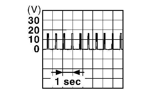 |
||||
| 3 | When a registered Intelligent Key backside is contacted to push-button ignition switch | 0 V | |||
| Other than above | 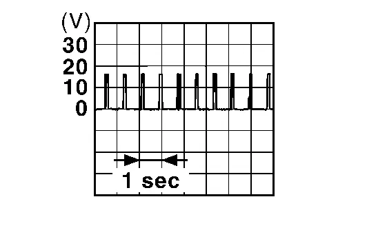 |
||||
Is the inspection result normal?
YES>>GO TO 3.
NO>>GO TO 2.
CHECK NATS ANTENNA AMP. COMMUNICATION SIGNAL CIRCUIT
Ignition switch OFF.
Disconnect Intelligent Key unit connector and push-button ignition switch connector.
Check continuity between push-button ignition switch harness connector and Intelligent Key unit harness connector.
Push-button ignition switch Intelligent Key unit Continuity Connector Terminal Connector Terminal M17 2 M38 19 Yes 3 20 Check continuity between push-button ignition switch harness connector and ground.
Push-button ignition switch (-) Continuity Connector Terminal M17 2 Ground No 3
Is the inspection result normal?
YES>>GO TO 3.
NO>>Repair or replace harness.
REPLACE PUSH-BUTTON IGNITION SWITCH
Replace push-button ignition switch. Refer to Removal and Installation.
Is the inspection result normal?
YES>>Inspection End.
NO>>GO TO 4.
REPLACE INTELLIGENT KEY UNIT
Replace Intelligent Key unit. Refer to Removal and Installation.
>>Inspection End.
Hood Switch Nissan Pathfinder SUV
Component Function Check
CHECK FUNCTION
 CONSULT
Select “HOOD SW (CAN)” or “Hood switch” in “Data Monitor” mode of “IPDM E/R”.
Check “HOOD SW (CAN)” or “Hood switch” indication under the following condition.
| Monitor item | Condition | Indication |
|---|---|---|
| HOOD SW (CAN) | Close the hood | Close |
| Open the hood | Open | |
| Transmits invalid CAN signal | NG | |
| Hood switch | Close the hood | Close |
| Open the hood | Open |
Is the indication normal?
YES>>Hood switch is OK.
NO>>Refer to Diagnosis Procedure.
Diagnosis Procedure
CHECK HOOD SWITCH SIGNAL CIRCUIT 1
Ignition switch OFF.
Disconnect hood switch connector.
Check voltage between hood switch harness connector and ground.
| (+) | (–) | Voltage (Approx.) | |
|---|---|---|---|
| Hood switch | |||
| Connector | Terminal | ||
| E234 | 1 | Ground | Battery voltage |
Is the inspection result normal?
YES>>GO TO 3.
NO>>GO TO 2.
CHECK HOOD SWITCH SIGNAL CIRCUIT 2
Disconnect IPDM E/R connector.
Check continuity between IPDM E/R harness connector and hood switch harness connector.
IPDM E/R Hood switch Continuity Connector Terminal Connector Terminal E217 52 E234 1 Yes Check continuity between IPDM E/R harness connector and ground.
IPDM E/R — Continuity Connector Terminal E217 52 Ground No
Is the inspection result normal?
YES>>Replace IPDM E/R. Refer to Removal and Installation.
NO>>Repair or replace harness.
CHECK HOOD SWITCH GROUND CIRCUIT
Check continuity between hood switch harness connector and ground.
| Hood switch | — | Continuity | |
|---|---|---|---|
| Connector | Terminal | ||
| E234 | 2 | Ground | Yes |
Is the inspection result normal?
YES>>GO TO 4.
NO>>Repair or replace harness.
CHECK HOOD SWITCH
Refer to Component Inspection.
Is the inspection result normal?
YES>>GO TO 5.
NO>>Replace hood lock assembly. Refer to Removal and Installation.
CHECK INTERMITTENT INCIDENT
Refer to Intermittent Incident.
>>Inspection End.
Component Inspection
CHECK HOOD SWITCH
Ignition switch OFF.
Disconnect hood switch connector.
Check continuity between hood switch terminals.
Hood switch Condition Continuity Terminal 1 2 Hood lock Unlock condition No Lock condition Yes
Is the inspection result normal?
YES>>Inspection End.
NO>>Replace hood lock assembly. Refer to Removal and Installation.
Horn Function Nissan Pathfinder 2022
Component Function Check
CHECK FUNCTION
 CONSULT
Ignition switch OFF.
Perform “HORN” in “ACTIVE TEST” mode of “IPDM E/R”.
Check the horn operation.
Test item Description HORN On Horn Sounds (for 20 ms.)
Is the operation normal?
YES>>Inspection End.
NO>>Refer to Diagnosis Procedure (Horn (Low)) or Diagnosis Procedure (Horn (High)).
Diagnosis Procedure (Horn (Low))
CHECK HORN FUNCTION
Check horn function with horn switch.
Do horns sound?
YES>>GO TO 2.
NO>>Perform the trouble diagnosis for horn circuit. Refer to Wiring Diagram.
CHECK HORN RELAY CONTROL SIGNAL
 CONSULT
Ignition switch ON.
Select "HORN" in "ACTIVE TEST" mode of "IPDM E/R".
Check voltage between IPDM E/R harness connector and ground.
| (+) | (–) | Test item | Voltage (Approx.) | ||
|---|---|---|---|---|---|
| IPDM E/R | |||||
| Connector | Terminal | ||||
| E119 | 9 | Ground | HORN | On | 0 V |
| Off | Battery voltage | ||||
Is operation normal?
YES>>GO TO 4.
NO>>GO TO 3.
CHECK IPDM E/R POWER SUPPLY CIRCUIT
Ignition switch OFF.
Disconnect horn relay-2 connector and IPDM E/R connector.
Check continuity between IPDM E/R harness connector and horn relay-2 harness connector.
IPDM E/R Horn relay-2 Continuity Connector Terminal Connector Terminal E119 9 E58 1 Yes Check continuity between IPDM E/R harness connector and ground.
IPDM E/R (–) Continuity Connector Terminal E119 9 Ground No
Is the inspection result normal?
YES>>GO TO 4.
NO>>Repair or replace harness.
CHECK INTERMITTENT INCIDENT
Refer to Intermittent Incident.
>>Inspection End.
Diagnosis Procedure (Horn (High))
CHECK HORN FUNCTION
Check horn function with horn switch.
Do horns sound?
YES>>GO TO 2.
NO>>Perform the trouble diagnosis for horn circuit. Refer to Wiring Diagram.
CHECK HORN RELAY CONTROL SIGNAL
 CONSULT
Ignition switch ON.
Select "HORN" in "ACTIVE TEST" mode of "IPDM E/R".
Check voltage between IPDM E/R harness connector and ground.
| (+) | (–) | Test item | Voltage (Approx.) | ||
|---|---|---|---|---|---|
| IPDM E/R | |||||
| Connector | Terminal | ||||
| E119 | 9 | Ground | HORN | On | 0 V |
| Off | Battery voltage | ||||
Is operation normal?
YES>>GO TO 4.
NO>>GO TO 3.
CHECK IPDM E/R POWER SUPPLY CIRCUIT
Ignition switch OFF.
Disconnect horn relay-1 connector and IPDM E/R connector.
Check continuity between IPDM E/R harness connector and horn relay-1 harness connector.
IPDM E/R Horn relay-1 Continuity Connector Terminal Connector Terminal E119 9 H-1 1 Yes Check continuity between IPDM E/R harness connector and ground.
IPDM E/R (–) Continuity Connector Terminal E119 9 Ground No
Is the inspection result normal?
YES>>GO TO 4.
NO>>Repair or replace harness.
CHECK INTERMITTENT INCIDENT
Refer to Intermittent Incident.
>>Inspection End.
Starter Cut Relay Nissan Pathfinder
Component Inspection
CHECK STARTER CUT RELAY
Ignition switch OFF.
Disconnect starter cut relay.
Check continuity between starter cut relay terminals.
Starter cut relay Condition Continuity Terminal 8 7 12 V direct current supply between terminals 5 and 6 Yes No current supply No
Is the inspection result normal?
YES>>Inspection End.
NO>>Replace starter cut relay.
Stop Lamp Switch Nissan Pathfinder R53
Component Inspection
CHECK STOP LAMP SWITCH
Ignition switch OFF.
Disconnect stop lamp switch connector.
Check continuity between stop lamp switch terminals.
Stop lamp switch Condition Continuity Terminal 1 2 Brake pedal Not depressed No Depressed Yes
Is the inspection result normal?
YES>>Inspection End.
NO>>Replace stop lamp switch. Refer to Exploded View.
Brake Pedal Position Switch Nissan Pathfinder 2022
Component Inspection
CHECK BRAKE PEDAL POSITION SWITCH
Ignition switch OFF.
Disconnect stop lamp switch connector.
Check continuity between brake pedal position switch terminals.
Brake pedal position switch Condition Continuity Terminal 1 2 Brake pedal Not depressed No Depressed Yes
Is the inspection result normal?
YES>>Inspection End.
NO>>Replace brake pedal position switch. Refer to Exploded View.