Audio, Visual & Navigation System - Dtc/circuit Diagnosis
- Power Supply and Ground Circuit
- Camera Image Signal Circuit
Power Supply and Ground Circuit Nissan Pathfinder Fifth generation
Av Control Unit
Diagnosis Procedure
CHECK FUSE
Check that the following fuse is not blown:
| Terminal No. | Signal name | Fuse No. | Capacity |
|---|---|---|---|
| 19 | Battery power supply | 25 | (20A) |
Are the fuses blown?
YES>>Replace the blown fuse after repairing the affected circuit.
NO>>GO TO 2.
CHECK POWER SUPPLY CIRCUIT
Ignition switch OFF.
Disconnect AV control unit connector.
Check voltage between AV control unit connector and ground.
AV control unit Ground Condition Voltage
(Approx.)Connector Terminal M121 19 — Ignition switch: OFF Battery voltage
Is the inspection result normal?
YES>>GO TO 3.
NO>>Repair or replace harness or connectors.
CHECK GROUND CIRCUIT
Check continuity between AV control unit connector M121 and ground.
| AV control unit | Ground | Continuity | |
|---|---|---|---|
| Connector | Terminal | ||
| M121 | 20 | — | Yes |
Is the inspection result normal?
YES>>Inspection End.
NO>>Repair or replace harness or connectors.
Camera Image Signal Circuit Nissan Pathfinder SUV
Diagnosis Procedure
CHECK CAMERA POWER SUPPLY CIRCUIT CONTINUITY
Ignition switch OFF.
Disconnect AV control unit connector M123 and rear view camera connector B462.
Check continuity between AV control unit connector M123 and rear view camera connector B462.
AV control unit Rear view camera Continuity Connector Terminal Connector Terminal M123 28 B462 2 Yes Check continuity between AV control unit connector M123 and ground.
AV control unit Ground Continuity Connector Terminal M123 28 No
Is inspection result normal?
YES>>GO TO 3.
NO>>Repair or replace harness or connectors.
CHECK CAMERA POWER SUPPLY VOLTAGE
Connect AV control unit connector M123 and rear view camera connector B462.
Ignition switch ON.
Shift the selector lever to R (reverse).
Check voltage between AV control unit connector M123 and ground.
AV control unit Ground Condition Voltage
(Approx.)(+) (−) Connector Terminal M123 28 — Selector lever is in “R”. 6.0 V
Is inspection result normal?
YES>>GO TO 4.
NO>>Replace AV control unit. Refer to Removal and Installation.
CHECK CAMERA IMAGE SIGNAL CIRCUIT CONTINUITY
Ignition switch OFF.
Disconnect AV control unit connector M123 and rear view camera connector B462.
Check continuity between AV control unit connector M123 and rear view camera connector B462.
AV control unit Rear view camera Continuity Connector Terminal Connector Terminal M123 49 B462 1 Yes Check continuity between AV control unit connector M123 and ground.
AV control unit Ground Continuity Connector Terminal M123 49 No
Is inspection result normal?
YES>>GO TO 5.
NO>>Repair or replace harness or connectors.
CHECK CAMERA GROUND CIRCUIT CONTINUITY
Check continuity between AV control unit connector M123 and rear view camera connector B462.
| AV control unit | Rear view camera | Continuity | ||
| Connector | Terminal | Connector | Terminal | |
| M123 | 29 | B462 | 4 | Yes |
Is inspection result normal?
YES>>GO TO 6.
NO>>Repair or replace harness or connectors.
CHECK CAMERA IMAGE SIGNAL
Connect AV control unit connector M123 and rear view camera connector B462.
Ignition switch ON.
Shift the selector lever to R (reverse).
Check signal between AV control unit connector M123 and ground.
AV control unit Ground Condition Reference value (+) (−) Connector Terminal M123 49 — Camera image displayed. 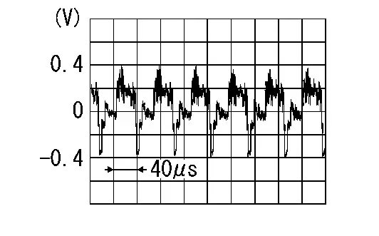
Is inspection result normal?
YES>>Replace AV control unit. Refer to Removal and Installation.
NO>>Replace rear view camera. Refer to Removal and Installation.