Driver Assistance System - Ecu Diagnosis Information
- Adas Control Unit 2
- Distance Sensor
- Front Camera Unit
- Side Radar Lh
Adas Control Unit 2 Nissan Pathfinder 2022
List of ECU Reference
| ECU | Reference |
|---|---|
| ADAS control unit 2 | Reference Value |
| Fail-safe (ADAS Control Unit 2) | |
| DTC Inspection Priority Chart | |
| DTC Index |
Distance Sensor Nissan Pathfinder 2026
Reference Value
VALUES ON THE DIAGNOSIS TOOL
| Monitor item | Condition | Value/Status | |
|---|---|---|---|
| Horizontal Alignment value | Ignition switch ON | (-3.7°) – (+3.7°) | |
| Vertical Alignment value | Ignition switch ON | (-2.5°) – (+3°) | |
| Horizontal Alignment value 2 | Ignition switch ON | (-5.7°) – (+5.7°) | |
| Vertical Alignment value 2 | Ignition switch ON | (-6.3°) – (+6.3°) | |
| Nissan Pathfinder Vehicle status for alignment | Ignition switch ON | When the Nissan Pathfinder vehicle condition is normal | OK |
| When the Nissan Pathfinder vehicle is moving | Vehicle | ||
| When the DTC is detected | System | ||
| When the Nissan Pathfinder vehicle is moving and the DTC is detected | No condi | ||
| Alignment status | Ignition switch ON | When the distance sensor alignment is not completed | Incomp |
| When the distance sensor alignment is completed | Comp | ||
| When the distance sensor alignment is running | Running | ||
| When the threshold is out of range | NG1 | ||
| When distance sensor has internal malfunction | NG2 | ||
| When the target is not detected or the timeout occurs | NG3 | ||
| When the Nissan Pathfinder vehicle is moving | NG4 | ||
| Alignment status 2 | Ignition switch ON | When the distance sensor alignment is completed | Comp |
| When the distance sensor alignment is not completed | Aborted | ||
| When the distance sensor alignment is running | Running | ||
| When the timeout occurs | NG1 | ||
| When the threshold is out of range | NG2 | ||
TERMINAL LAYOUT

PHYSICAL VALUES
Terminal No. (Wire color) | Description | Condition | Value (Approx.) | |||
|---|---|---|---|---|---|---|
| + | – | Signal name | Input/Output | |||
1 (B) |
Ground | Ground | — | Ignition switch ON | 0 V | |
2 (R) |
1 (B) |
ITS CAN communication-L | — | — | — | |
3 (BR) |
ITS CAN communication-H | — | — | — | ||
4 (P) |
Ignition power supply | Input | Ignition switch ON | Battery voltage | ||
5 (SHIELD) |
— | Shield | — | — | — | |
8 (Y) |
Ethernet(+) | — | — | — | ||
9 (G) |
Ethernet(-) | — | — | — | ||
Fail-safe
Refer to Fail-safe (Distance sensor).
DTC Inspection Priority Chart
If multiple DTCs are detected simultaneously, check them one by one depending on the following DTC inspection priority chart.
C2580-45: Distance sensor
C2580-47: Distance sensor
C2580-48: Distance sensor
C2580-49: Distance sensor
C2580-4B: Distance sensor
C2580-55: Distance sensor
C2581-78: Distance sensor
C2581-92: Distance sensor
C2582-97: Distance sensor
C2584-02: Distance sensor
C2587-16: POWER SUPPLY CIRCUIT
C2587-17: POWER SUPPLY CIRCUIT
C2599-13: Ethernet circuit
U275F-88: Ethernet circuit
U2A07-88: CAN comm err (ITS2-CAN Bus Off)
U2104-87: CAN comm err (active steering)
U2140-87: CAN comm err (ECM)
U2141-87: CAN comm err (TCM)
U2148-87: CAN comm err (brake control unit)
U214F-87: CAN comm err (BCM)
U2152-87: CAN comm err (ADAS control unit)
U2156-87: CAN comm err (steering angle sensor)
U215B-87: CAN comm err (IPDM E/R)
C2585-87: CAN comm err
C2588-87: ADAS control unit
C2589-81: TCM
C2589-82: TCM
C2589-86: TCM
C2589-87: TCM
C258B-82: A/C auto amp.
C258B-86: A/C auto amp.
C258E-81: ABS
C258E-82: ABS
C258E-86: ABS
C258E-87: ABS
C258F-81: IPDM E/R
C258F-82: IPDM E/R
C258F-86: IPDM E/R
C258F-87: IPDM E/R
C2591-81: BCM
C2591-82: BCM
C2591-86: BCM
C2591-87: BCM
C2592-81: ECM
C2592-82: ECM
C2592-86: ECM
C2595-81: EPS control unit
C2595-86: EPS control unit
C2595-87: EPS control unit
U2140-83: CAN comm err (ECM)
U2141-83: CAN comm err (TCM)
U2148-83: CAN comm err (brake control unit)
U214F-83: CAN comm err (BCM)
U2152-83: CAN comm err (ADAS control unit)
U215B-83: CAN comm err (IPDM E/R)
DTC Index
×: Applicable
| DTC | Items (CONSULT screen terms) | Fail-safe | Reference | |||||
|---|---|---|---|---|---|---|---|---|
| Nissan Pathfinder Vehicle-to-vehicle distance control mode | Conventional (fixed speed) cruise control mode | Steering wheel assistance function | AEB | I-FCW | ||||
| C2580 | 45 | Distance sensor | × | × | × | × | × | DTC Description |
| 47 | × | × | × | × | × | DTC Description | ||
| 48 | × | × | × | × | × | DTC Description | ||
| 49 | × | × | × | × | × | DTC Description | ||
| 4B | × | × | × | × | × | DTC Description | ||
| 55 | × | × | × | × | × | DTC Description | ||
| C2581 | 78 | Distance sensor | × | × | × | × | × | DTC Description |
| 92 | × | × | × | × | × | DTC Description | ||
| C2582 | 97 | Distance sensor | × | × | × | × | × | DTC Description |
| C2584 | 02 | Distance sensor | × | × | × | × | × | DTC Description |
| C2585 | 87 | CAN comm err | × | × | × | × | × | DTC Description |
| C2587 | 16 | POWER SUPPLY CIRCUIT | × | × | × | × | × | DTC Description |
| 17 | × | × | × | × | × | DTC Description | ||
| C2588 | 87 | ADAS control unit | × | × | × | × | × | DTC Description |
| C2589 | 81 | TCM | × | × | × | × | × | DTC Description |
| 82 | × | × | × | × | × | DTC Description | ||
| 86 | × | × | × | × | × | DTC Description | ||
| 87 | × | × | × | × | × | DTC Description | ||
| C258B | 82 | A/C auto amp. | × | × | × | × | × | DTC Description |
| 86 | × | × | × | × | × | DTC Description | ||
| C258E | 81 | ABS | × | × | × | × | × | DTC Description |
| 82 | × | × | × | × | × | DTC Description | ||
| 86 | × | × | × | × | × | DTC Description | ||
| 87 | × | × | × | × | × | DTC Description | ||
| C258F | 81 | IPDM E/R | × | × | × | × | × | DTC Description |
| 82 | × | × | × | × | × | DTC Description | ||
| 86 | × | × | × | × | × | DTC Description | ||
| 87 | × | × | × | × | × | DTC Description | ||
| C2591 | 81 | BCM | × | × | × | × | × | DTC Description |
| 82 | × | × | × | × | × | DTC Description | ||
| 86 | × | × | × | × | × | DTC Description | ||
| 87 | × | × | × | × | × | DTC Description | ||
| C2592 | 81 | ECM | × | × | × | × | × | DTC Description |
| 82 | × | × | × | × | × | DTC Description | ||
| 86 | × | × | × | × | × | DTC Description | ||
| C2595 | 81 | EPS control unit | × | × | × | × | × | DTC Description |
| 86 | × | × | × | × | × | DTC Description | ||
| 87 | × | × | × | × | × | DTC Description | ||
| C2599 | 13 | Ethernet circuit | × | × | × | × | × | DTC Description |
| U275F | 88 | Ethernet circuit | × | × | × | × | × | DTC Description |
×: Applicable
| DTC | Items (CONSULT screen terms) | Fail-safe | Reference | |||||
|---|---|---|---|---|---|---|---|---|
| Nissan Pathfinder Vehicle-to-vehicle distance control mode | Conventional (fixed speed) cruise control mode | Steering wheel assistance function | AEB | I-FCW | ||||
| U2104 | 87 | CAN comm err (active steering) | × | × | × | × | × | DTC Description |
| U2140 | 83 | CAN comm err (ECM) | × | × | × | × | × | DTC Description |
| 87 | × | × | × | × | × | DTC Description | ||
| U2141 | 83 | CAN comm err (TCM) | × | × | × | × | × | DTC Description |
| 87 | × | × | × | × | × | DTC Description | ||
| U2148 | 83 | CAN comm err (brake control unit) | × | × | × | × | × | DTC Description |
| 87 | × | × | × | × | × | DTC Description | ||
| U214F | 83 | CAN comm err (BCM) | × | × | × | × | × | DTC Description |
| 87 | × | × | × | × | × | DTC Description | ||
| U2152 | 83 | CAN comm err (ADAS control unit) | × | × | × | × | × | DTC Description |
| 87 | × | × | × | × | × | DTC Description | ||
| U2156 | 87 | CAN comm err (steering angle sensor) | × | × | × | × | × | DTC Description |
| U215B | 83 | CAN comm err (IPDM E/R) | × | × | × | × | × | DTC Description |
| 87 | × | × | × | × | × | DTC Description | ||
| U2A07 | 88 | CAN comm err (ITS2-CAN Bus Off) | × | × | × | × | × | DTC Description |
Front Camera Unit Nissan Pathfinder 2022
Reference Value
VALUES ON THE DIAGNOSIS TOOL
| Monitor item | Condition | Value/Status | ||
|---|---|---|---|---|
| AIMING DONE | Ignition switch ON | When the camera aiming is not completed | 0 | |
| When the camera aiming is completed | 1 | |||
| AIMING RESULT | Ignition switch ON | When the camera aiming is NG completed | 0 | |
| When the camera aiming is normal completed | 1 | |||
| AIM NG REASON | Ignition switch ON | When the camera aiming is normal completed | 0 | |
| When the front camera unit has an internal communication error | 1 | |||
| When the front camera unit has an internal data error | 2 | |||
| When the front camera unit has a target information error | 3 | |||
| When the front camera unit has a aiming mode error | 4 | |||
| When a timeout occurs | 5 | |||
| When the front camera unit cannot transition to aiming mode | 6 | |||
| When the front camera unit has a memory writing error | 7 | |||
| When the condition of the front camera unit installation is not correct | 8 | |||
| When all correction values are outside the threshold | 9 | |||
| When NG reason is unknown | 16 | |||
| When the front camera unit cannot detect the target | 18 | |||
| When the roll angle is outside the threshold | 19 | |||
| When the front camera unit cannot calculate the aiming correction values | 20 | |||
| When the front camera unit cannot read the distance to target board | 21 | |||
| When the entered "Dt" value is not correct | 22 | |||
| When the entered "Ts" value is not correct | 23 | |||
| When the yaw correction values are outside the threshold | 24 | |||
| When the pitch correction values are outside the threshold | 25 | |||
| When several targets are detected | 26 | |||
| When an error is detected during the camera aiming | 27 | |||
| When NG reason is unknown | 255 | |||
| AIM YAW | Ignition switch ON | 0 ± 3.0 deg | ||
| AIM ROL | Ignition switch ON | 0 ± 3.0 deg | ||
| AIM PIT | Ignition switch ON | 0 ± 3.0 deg | ||
| FCTRY AIM YAW | Ignition switch ON | 0 ± 3.0 deg | ||
| FCTRY AIM ROL | Ignition switch ON | 0 ± 3.0 deg | ||
| FCTRY AIM PIT | Ignition switch ON | 0 ± 3.0 deg | ||
| Configuration result 1 | Ignition switch ON | When the configuration is completed | Finished | |
| When the configuration is not completed | Unfnshd | |||
| Configuration status | Ignition switch ON | When the configuration is completed | OK | |
| When the configuration is not completed | NG1 | |||
| When the threshold is out of range | NG2 | |||
| When the front camera unit has internal malfunction | NG3 | |||
| When the front camera unit has internal malfunction | NG4 | |||
| When the front camera unit has communication error | NG5 | |||
| When the front camera unit fails to write | NG6 | |||
| Heater system | Ignition switch ON | Off | ||
| ECU power supply voltage | Ignition switch ON | 6.4 – 16 V | ||
| Configuration type | Ignition switch ON | Type2 | ||
| Engine type | Ignition switch ON | Gasoline | ||
| Manufacturer | Ignition switch ON | Nissan | ||
| Nissan Pathfinder Vehicle width | Ignition switch ON | 1.84 | ||
| Transmission type | Ignition switch ON | AT/CVT | ||
| ALH | Ignition switch ON | When the ALH system is installed | On | |
| When the ALH system is not installed | Off | |||
| HBA function | Ignition switch ON | When the HBA is ON | On | |
| When the HBA is OFF | Off | |||
| Camera image bottom | Ignition switch ON | 24 pixel | ||
| Camera height | Ignition switch ON | 1,501 mm | ||
| Camera distance 1 | Ignition switch ON | 895 mm | ||
| Camera distance 2 | Ignition switch ON | 943 mm | ||
| Camera offset | Ignition switch ON | 0 mm | ||
| Camera pitch | Ignition switch ON | 0.609 deg | ||
| Nissan Pathfinder Vehicle speed | While driving | Almost the same speed as speedometer indication | ||
TERMINAL LAYOUT

PHYSICAL VALUES
Terminal No. (Wire color) | Description | Condition | Value (Approx.) | ||
|---|---|---|---|---|---|
| + | – | Signal name | Input/Output | ||
3 (R) |
8 (B) |
ITS CAN communication-L | — | — | — |
5 (LA/LG) |
Ignition power supply | Input | Ignition switch ON | Battery voltage | |
7 (BR) |
ITS CAN communication-H | — | — | — | |
8 (B) |
Ground | Ground | — | Ignition switch ON | 0 V |
9 (SHIELD) |
— | Shield | — | — | — |
10 (G) |
Ethernet(-) | — | — | — | |
11 (Y) |
Ethernet(+) | — | — | — | |
Fail-safe
Refer to Fail-safe (Front Camera Unit).
DTC Inspection Priority Chart
If some DTCs are displayed at the same time, perform inspections one by one based on the following priority chart.
C2502-55: Configuration data error
C2502-92: Configuration data error
C2503-54: Camera aiming incmp
C2503-78: Configuration data error
C2504-71: Configuration data error
C2505-92: Configuration data error
C2524-82: Configuration data error
C2524-83: Configuration data error
C2524-86: Configuration data error
C2524-87: Configuration data error
C2531-86: Configuration data error
C2531-87: Configuration data error
C2570-4B: Configuration data error
C2571-71: Configuration data error
C2572-71: Configuration data error
C2573-97: Configuration data error
C2575-92: Configuration data error
C2576-97: Configuration data error
U2104-87: Configuration data error
U2140-87: CAN comm err (ECM)
U2141-87: CAN comm err (TCM)
U2142-87: Configuration data error
U2148-87: CAN comm err (brake control unit)
U214E-87: CAN comm err (combination meter)
U214F-87: CAN comm err (BCM)
U2150-87: CAN comm err (AIRBAG)
U2152-87: CAN comm err (ADAS control unit)
U2154-87: CAN comm err (MIU)
U2156-87: Configuration data error
U215B-87: CAN comm err (IPDM E/R)
U276B-88: Ethernet circuit
U2A07-88: CAN comm circuit
C2507-16: Power supply circuit
C2507-17: Power supply circuit
C2500-49: Camera unit malf
C2501-4B: Front camera unit
C2506-49: Front camera unit
C2520-82: BCM
C2520-83: BCM
C2520-86: BCM
C2520-87: BCM
C2521-82: ECM
C2521-83: ECM
C2521-86: ECM
C2521-87: ECM
C2522-82: ABS
C2522-83: ABS
C2522-86: ABS
C2522-87: ABS
C2523-86: Combination meter
C2523-87: Combination meter
C2525-86: AV control unit
C2525-87: AV control unit
C2526-82: ADAS control unit
C2526-83: ADAS control unit
C2526-86: ADAS control unit
C2526-87: ADAS control unit
C2527-82: TCM
C2527-83: TCM
C2527-86: TCM
C2527-87: TCM
C2528-82: IPDM E/R
C2528-83: IPDM E/R
C2528-86: IPDM E/R
C2528-87: IPDM E/R
C2529-86: Air bag diagnosis sensor unit
C2529-87: Air bag diagnosis sensor unit
DTC Index
×:Applicable
| DTC | Items (CONSULT screen terms) | Fail-safe | Reference | ||||||||
|---|---|---|---|---|---|---|---|---|---|---|---|
| Nissan Pathfinder Vehicle-to-vehicle distance control mode | Conven tional (fixed speed) cruise control mode | Steering wheel assistance function | AEB | LDW | I-LI | I-BSI | TSR | ||||
| C2500 | 49 | Camera unit malf | × | × | × | × | × | × | × | × | DTC Description |
| C2501 | 4B | Front camera unit | × | × | × | × | × | × | × | × | DTC Description |
| C2502 | 55 | Configuration data error | × | × | × | × | × | × | × | × | DTC Description |
| 92 | × | × | × | × | × | × | × | × | DTC Description | ||
| C2503 | 54 | Camera aiming incmp | × | × | × | × | × | × | × | × | DTC Description |
| C2503 | 78 | Configuration data error | × | × | × | × | × | × | × | × | DTC Description |
| C2504 | 71 | Configuration data error | × | × | × | × | × | × | × | × | DTC Description |
| C2505 | 92 | Configuration data error | × | × | × | × | × | × | × | × | DTC Description |
| C2506 | 49 | Front camera unit | × | × | × | × | × | × | × | × | DTC Description |
| C2507 | 16 | Power supply circuit | × | × | × | × | × | × | × | × | DTC Description |
| 17 | × | × | × | × | × | × | × | × | DTC Description | ||
| C2520 | 82 | BCM | × | × | × | × | × | × | × | × | DTC Description |
| 83 | × | × | × | × | × | × | × | × | DTC Description | ||
| 86 | × | × | × | × | × | × | × | × | DTC Description | ||
| 87 | × | × | × | × | × | × | × | × | DTC Description | ||
| C2521 | 82 | ECM | × | × | × | × | × | × | × | × | DTC Description |
| 83 | × | × | × | × | × | × | × | × | DTC Description | ||
| 86 | × | × | × | × | × | × | × | × | DTC Description | ||
| 87 | × | × | × | × | × | × | × | × | DTC Description | ||
| C2522 | 82 | ABS | × | × | × | × | × | × | × | × | DTC Description |
| 83 | × | × | × | × | × | × | × | × | DTC Description | ||
| 86 | × | × | × | × | × | × | × | × | DTC Description | ||
| 87 | × | × | × | × | × | × | × | × | DTC Description | ||
| C2523 | 86 | Combination meter | × | × | × | × | × | × | × | × | DTC Description |
| 87 | × | × | × | × | × | × | × | × | DTC Description | ||
| C2524 | 82 | Configuration data error | × | × | × | × | × | × | × | × | DTC Description |
| 83 | × | × | × | × | × | × | × | × | DTC Description | ||
| 86 | × | × | × | × | × | × | × | × | DTC Description | ||
| 87 | × | × | × | × | × | × | × | × | DTC Description | ||
| C2525 | 86 | AV control unit | × | × | × | × | × | × | × | × | DTC Description |
| 87 | × | × | × | × | × | × | × | × | DTC Description | ||
| C2526 | 82 | ADAS control unit | × | × | × | × | × | × | × | × | DTC Description |
| 83 | × | × | × | × | × | × | × | × | DTC Description | ||
| 86 | × | × | × | × | × | × | × | × | DTC Description | ||
| 87 | × | × | × | × | × | × | × | × | DTC Description | ||
| C2527 | 82 | TCM | × | × | × | × | × | × | × | × | DTC Description |
| 83 | × | × | × | × | × | × | × | × | DTC Description | ||
| 86 | × | × | × | × | × | × | × | × | DTC Description | ||
| 87 | × | × | × | × | × | × | × | × | DTC Description | ||
| C2528 | 82 | IPDM E/R | × | × | × | × | × | × | × | × | DTC Description |
| 83 | × | × | × | × | × | × | × | × | DTC Description | ||
| 86 | × | × | × | × | × | × | × | × | DTC Description | ||
| 87 | × | × | × | × | × | × | × | × | DTC Description | ||
| C2529 | 86 | Air bag diagnosis sensor unit | × | × | × | × | × | × | × | × | DTC Description |
| 87 | × | × | × | × | × | × | × | × | DTC Description | ||
| C2531 | 86 | Configuration data error | × | × | × | × | × | × | × | × | DTC Description |
| 87 | × | × | × | × | × | × | × | × | DTC Description | ||
| C2570 | 4B | Configuration data error | × | × | × | × | × | × | × | × | DTC Description |
| C2571 | 71 | Configuration data error | × | × | × | × | × | × | × | × | DTC Description |
| C2572 | 71 | Configuration data error | × | × | × | × | × | × | × | × | DTC Description |
| C2573 | 97 | Configuration data error | × | × | × | × | × | × | × | × | DTC Description |
| C2575 | 92 | Configuration data error | × | × | × | × | × | × | × | × | DTC Description |
| C2576 | 97 | Configuration data error | × | × | × | × | × | × | × | × | DTC Description |
| U2104 | 87 | Configuration data error | × | × | × | × | × | × | × | × | DTC Description |
| U2142 | 87 | Configuration data error | × | × | × | × | × | × | × | × | DTC Description |
| U2156 | 87 | Configuration data error | × | × | × | × | × | × | × | × | DTC Description |
| U276B | 88 | Ethernet circuit | × | × | × | × | × | × | × | × | DTC Description |
×:Applicable
| DTC | Items (CONSULT screen terms) | Fail-safe | Reference | ||||||||
|---|---|---|---|---|---|---|---|---|---|---|---|
| Nissan Pathfinder Vehicle-to-vehicle distance control mode | Conven tional (fixed speed) cruise control mode | Steering wheel assistance function | AEB | LDW | I-LI | I-BSI | TSR | ||||
| U2140 | 87 | CAN comm err (ECM) | × | × | × | × | × | × | × | × | DTC Description |
| U2141 | 87 | CAN comm err (TCM) | × | × | × | × | × | × | × | × | DTC Description |
| U2148 | 87 | CAN comm err (brake control unit) | × | × | × | × | × | × | × | × | DTC Description |
| U214E | 87 | CAN comm err (combination meter) | × | × | × | × | × | × | × | × | DTC Description |
| U214F | 87 | CAN comm err (BCM) | × | × | × | × | × | × | × | × | DTC Description |
| U2150 | 87 | CAN comm err (AIRBAG) | × | × | × | × | × | × | × | × | DTC Description |
| U2152 | 87 | CAN comm err (ADAS control unit) | × | × | × | × | × | × | × | × | DTC Description |
| U2154 | 87 | CAN comm err (MIU) | × | × | × | × | × | × | × | × | DTC Description |
| U215B | 87 | CAN comm err (IPDM E/R) | × | × | × | × | × | × | × | × | DTC Description |
| U2A07 | 88 | CAN comm circuit | × | × | × | × | × | × | × | × | DTC Description |
Side Radar Lh Nissan Pathfinder Fifth generation
Reference Value
VALUES ON THE DIAGNOSIS TOOL
| Monitor item | Condition | Value/Status | |
|---|---|---|---|
| BSW select | Ignition switch ON | When the BSW is ON | On |
| When the BSW is OFF | Off | ||
| RCTA select | Ignition switch ON | When the RCTA is ON | On |
| When the RCTA is OFF | Off | ||
| Horizontal alignment value | Ignition switch ON | (-5 deg) – (+5 deg) | |
| Vertical alignment value | — | ||
TERMINAL LAYOUT
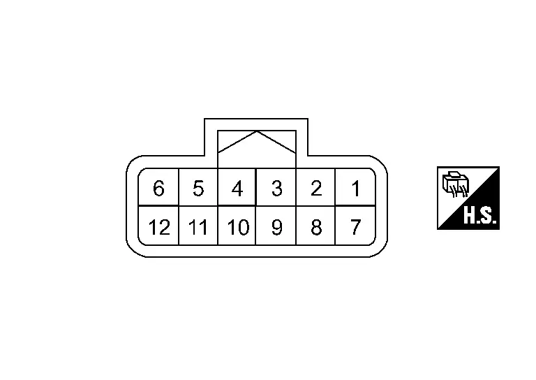
PHYSICAL VALUES
Terminal No. (Wire color) | Description | Condition | Value (Approx.) | ||
|---|---|---|---|---|---|
| + | – | Signal name | Input/Output | ||
1 (BR) |
10 (B) |
ITS CAN communication-H | — | — | — |
2 (LG) |
ITS CAN communication-L | — | — | — | |
6 (G) |
BSW indicator signal | Output | Approx. 2 sec. after ignition switch OFF ⇒ ON (bulb check) | 12 V | |
10 (B) |
Ground | Ground | — | Ignition switch ON | 0 V |
11 (B) |
10 (B) |
Switching signal | — | — | 0 V |
12 (BG) |
Ignition power supply | Input | Ignition switch ON | Battery voltage | |
Fail-safe
Refer to Fail-safe (Side Radar).
DTC Inspection Priority Chart
If some DTCs are displayed at the same time, perform inspections one by one based on the following priority chart.
C1E00-44: Control unit
C1E00-45: Control unit
C1E00-46: Control unit
C1E00-47: Control unit
C1E00-48: Control unit
C1E00-49: Control unit
C1E00-4B: Control unit
C1E00-97: Control unit
C1E01-12: Incorrect installation location
C1E01-67: Incorrect installation location
C1E10-54: Radar off-center
C1E10-78: Radar off-center
C1E11-97: RADAR BLOCKED
C1E12-16: Power supply circuit
C1E12-17: Power supply circuit
C1E13-55: Configuration unfinished
U2A08-88: CAN comm err (ITS3/5-CAN Bus Off)
U1B26-15: BSW/BSI IND OPEN CIR
U2104-87: CAN comm err (active steering)
U2141-87: CAN comm err (TCM)
U2148-87: CAN comm err (brake control unit)
U214E-87: CAN comm err (combination meter)
U214F-87: CAN comm err (BCM)
U2152-87: CAN comm err (ADAS control unit)
U2154-87: CAN comm err (MIU)
U2156-87: CAN comm err (steering angle sensor)
U215B-87: CAN comm err (IPDM E/R)
U216E-87: CAN comm err (side radar)
U1B2E-86: CAN comm err
U1B2E-87: CAN comm err
DTC Index
×: Applicable
| DTC | Items (CONSULT screen terms) | Fail-safe | Reference | |||
|---|---|---|---|---|---|---|
| BSW | I-BSI | RCTA | ||||
| C1E00 | 44 | Control unit | × | × | × | DTC Description |
| 45 | × | × | × | DTC Description | ||
| 46 | × | × | × | DTC Description | ||
| 47 | × | × | × | DTC Description | ||
| 48 | × | × | × | DTC Description | ||
| 49 | × | × | × | DTC Description | ||
| 4B | × | × | × | DTC Description | ||
| 97 | × | × | × | DTC Description | ||
| C1E01 | 12 | Incorrect installation location | × | × | × | DTC Description |
| 67 | × | × | × | DTC Description | ||
| C1E10 | 54 | Radar off-center | × | × | × | DTC Description |
| 78 | × | × | × | DTC Description | ||
| C1E11 | 97 | RADAR BLOCKED | × | × | × | DTC Description |
| C1E12 | 16 | Power supply circuit | × | × | × | DTC Description |
| 17 | × | × | × | DTC Description | ||
| C1E13 | 55 | Configuration unfinished | × | × | × | DTC Description |
| U1B26 | 15 | BSW/BSI IND OPEN CIR | × | × | × | DTC Description |
×: Applicable
| DTC | Items (CONSULT screen terms) | Fail-safe | Reference | |||
|---|---|---|---|---|---|---|
| BSW | I-BSI | RCTA | ||||
| U1B2E | 86 | CAN comm err | × | × | × | DTC Description |
| 87 | × | × | × | DTC Description | ||
| U2104 | 87 | CAN comm err (active steering) | × | × | × | DTC Description |
| U2141 | 87 | CAN comm err (TCM) | × | × | × | DTC Description |
| U2148 | 87 | CAN comm err (brake control unit) | × | × | × | DTC Description |
| U214E | 87 | CAN comm err (combination meter) | × | × | × | DTC Description |
| U214F | 87 | CAN comm err (BCM) | × | × | × | DTC Description |
| U2152 | 87 | CAN comm err (ADAS control unit) | × | × | × | DTC Description |
| U2154 | 87 | CAN comm err (MIU) | × | × | × | DTC Description |
| U2156 | 87 | CAN comm err (steering angle sensor) | × | × | × | DTC Description |
| U215B | 87 | CAN comm err (IPDM E/R) | × | × | × | DTC Description |
| U216E | 87 | CAN comm err (side radar) | × | × | × | DTC Description |
| U2A08 | 88 | CAN comm err (ITS3/5-CAN Bus Off) | × | × | × | DTC Description |