Transmission & Driveline :: Transaxle & Transmission

9at: Ge9f01a

In this manual: Transmission & Driveline :: Transaxle & Transmission
General Information — 8Engine :: Engine Mechanical — 19Engine Lubrication System - Precautions. Preparation — 1Engine Lubrication System - Lubrication System (System Description). Engine Oil Pressure (Basic Inspection). Service Data and Specifications (SDS) — 1Engine Cooling System - Precautions. Preparation. Service Data and Specifications (SDS) — 1Engine Cooling System - Engine Coolant — 1Engine Control System - System Description — 1System Description - Component Parts ++ — 1System Description - System ++ — 1Engine Control System - Ecu Diagnosis Information — 1Ecu Diagnosis Information - Ecm ++ — 1Engine Control System - Basic Inspection — 1Basic Inspection - Diagnosis and Repair Workflow ++ — 1Basic Inspection - Basic Inspection ++ — 1Basic Inspection - Additional Service When Replacing Ecm ++ — 1Basic Inspection - Fuel Pressure Check ++ — 1Basic Inspection - How to Set Srt Code ++ — 1Basic Inspection - How to Erase Permanent Dtc ++ — 1Engine Control System - Dtc/circuit Diagnosis — 1Engine Control System - Symptom Diagnosis — 1Engine Control System - Periodic Maintenance — 1Engine Control System - Removal and Installation — 1Fuel System - Precautions. Preparation. Service Data and Specifications (SDS) — 1Fuel System - Fuel System (Periodic Maintenance). Fuel Level Sensor Unit (Disassembly and Assembly) — 1Exhaust System - Precautions. Preparation — 1Exhaust System - Exhaust System (Periodic Maintenance). Exhaust System (Removal and Installation) — 1Starting System - Precautions. Preparation. Starter Motor (Service Data and Specifications (sds)) — 1Starting System - Diagnosis and Repair Work Flow — 1Starting System - Starting System (Symptom Diagnosis). Starter Motor (Removal and Installation) — 1Accelerator Control System - Precautions. Service Data and Specifications (SDS) — 1Accelerator Control System - Accelerator Pedal Assembly — 1Transmission & Driveline :: Transaxle & Transmission — 21Driveline - System Description — 1Transfer: Ty92b - Ecu Diagnosis Information. Awd Control Unit ++ — 1Driveline - Basic Inspection — 1Driveline - Dtc/circuit Diagnosis — 1Driveline - Symptom Diagnosis — 1Driveline - Removal and Installation — 1Transfer: Ty92b - Unit Removal and Installation. Transfer Assembly ++ — 1Driveline - Unit Disassembly and Assembly — 1Driveline - Basic Inspection — 1Driveline - Removal and Installation — 1Driveline - Unit Disassembly and Assembly — 1Front Axle - Precautions. Preparation — 1Front Axle - Noise, Vibration and Harshness (nvh) Troubleshooting (Symptom Diagnosis). Service Data and Specifications (SDS) — 1Front Axle - Front Drive Shaft Boot — 1Front Axle - Front Drive Shaft — 1Rear Axle - Precautions. Preparation. Service Data and Specifications (SDS) — 1Rear Axle - Noise, Vibration and Harshness (nvh) Troubleshooting — 1Rear Axle - Rear Drive Shaft — 1Suspension :: Front Suspension — 7Rear Suspension - Precautions. Preparation — 1Rear Suspension - Noise, Vibration and Harshness (nvh) Troubleshooting (Symptom Diagnosis). Service Data and Specifications (SDS) — 1Rear Suspension - Rear Suspension Assembly — 1Road Wheels & Tires - Precautions — 1Road Wheels & Tires - Preparation. Bcm (Ecu Diagnosis Information). Service Data and Specifications (SDS) — 1Road Wheels & Tires - System — 1Brakes :: Brake System — 9Parking Brake System - Precautions. Preparation — 1Parking Brake System - System — 1Vdc/tcs/abs - Precautions ++ — 1Brake Control System - System Description — 1System Description - Component Parts ++ — 1System Description - System ++ — 1Brake Control System - Basic Inspection — 1Brake Control System - Symptom Diagnosis — 1Brake Control System - Removal and Installation — 1Brake Control System - System Description — 1Brake Control System - Dtc/circuit Diagnosis — 1Brake Control System - Removal and Installation — 1Brake Control System - System Description — 1Brake Control System - Basic Inspection — 1Brake Control System - Symptom Diagnosis — 1Brake Control System - System Description — 1Brake Control System - Basic Inspection — 1Brake Control System - Symptom Diagnosis — 1Steering :: Steering System — 9Steering Control System - Precautions — 1Steering Control System - System — 1Steering Control System - Eps Control Unit (Ecu Diagnosis Information. Removal and Installation) — 1Restraints :: Seat Belt — 7Srs Air Bag - Precautions. Preparation — 1Srs Air Bag - Collision Diagnosis — 1Srs Air Bag - Occupant Classification System — 1Srs Air Bag Control System - Precautions — 1Srs Air Bag Control System - System — 1Srs Air Bag Control System - Diagnosis Sensor Unit — 1Srs Air Bag Control System - Inspection and Adjustment — 1Ventilation, Heater & Air Conditioner :: Ventilation System — 6Heater & Air Conditioning System - Precautions — 1Heater & Air Conditioning System - Preparation — 1Heater & Air Conditioning System - Component Parts — 1Heater & Air Conditioning System - Diagnosis and Repair Work Flow — 1Heater & Air Conditioning System - Compressor — 1Heater & Air Conditioning System - Cooler Pipe and Hose — 1Heater & Air Conditioning System - Condenser. Condenser — 1Heater & Air Conditioning System - Heating and Cooling Unit Assembly — 1Heater & Air Conditioning System - Service Data and Specifications (SDS) — 1Heater & Air Conditioning Control System - System Description — 1System Description - Component Parts ++ — 1System Description - System ++ — 1System Description - Operation ++ — 1Heater & Air Conditioning Control System - Ecu Diagnosis Information — 1Heater & Air Conditioning Control System - Basic Inspection — 1Heater & Air Conditioning Control System - Dtc/circuit Diagnosis — 1Heater & Air Conditioning Control System - Symptom Diagnosis — 1Heater & Air Conditioning Control System - Removal and Installation — 1Body Interior :: Interior — 8Instrument Panel - Precautions. Preparation. Clip List — 1Instrument Panel - Squeak and Rattle Trouble Diagnoses — 1Instrument Panel - Cluster Lid C — 1Seat - Precautions — 1Seat - Preparation. Clip List — 1Seat - Component Parts — 1Seat - System — 1Seat - Diagnosis and Repair Work Flow — 1Seat - Front Seat — 1Seat - Second Row Seats — 1Seat - Third Row Seats — 1Seat - Front Seat — 1Seat - Second Row Seat — 1Seat - Third Row Seat — 1Automatic Drive Positioner - Precautions. Preparation — 1Automatic Drive Positioner - System — 1Automatic Drive Positioner - Diagnosis and Repair Work Flow — 1Automatic Drive Positioner - Inspection and Adjustment — 1Body Exterior, Doors, Roof & Vehicle Security :: Door & Lock — 38Security Control System - Precautions — 1Security Control System - System — 1Security Control System - Ecm, Bcm, Intelligent Key Unit, Ipdm E/r — 1Security Control System - Vehicle Security System Cannot Be Set — 1Glass & Window System - Precautions. Preparation — 1Glass & Window System - Squeak and Rattle Trouble Diagnoses — 1Power Window Control System - Precautions. Preparation — 1Power Window Control System - Power Supply and Ground Circuit — 1Power Window Control System - Power Window Motor Circuit — 1Power Window Control System - Front Power Window Rh Alone Does Not Operate — 1Power Window Control System - Rear Lh Side Power Window Alone Does Not Operate — 1Power Window Control System - Rear Rh Side Power Window Alone Does Not Operate — 1Roof - Precautions. Preparation — 1Roof - Power Supply and Ground Circuit — 1Roof - Moonroof Switch Assembly — 1Roof - Lin Communication Circuit — 1Roof - Auto Operation Does Not Operate — 1Roof - Anti-Pinch Function Does Not Operate — 1Exterior - Precautions. Preparation. Clip List (Preparation) — 1Exterior - Squeak and Rattle Trouble Diagnoses — 1Exterior - Fender Protector — 1Exterior - Over Fender — 1Exterior - Under Cover — 1Exterior - Roof Side Rail — 1Body Repair - Service Information — 1Service Information - Sheet Metal Work ++ — 1Service Information - Body Welding and Precautions ++ — 1Service Information - Safety and Health ++ — 1Service Information - Repairing Procedures and Precautions ++ — 1Body Repair - Precaution — 1Body Repair - Preparation — 1Body Repair - Removal and Installation — 1Driver Controls :: Mirrors — 8Exterior Lighting System - System Description — 1System Description - Component Parts ++ — 1Exterior Lighting System - Basic Inspection — 1Exterior Lighting System - Dtc/circuit Diagnosis — 1Exterior Lighting System - Symptom Diagnosis — 1Exterior Lighting System - Periodic Maintenance — 1Exterior Lighting System - Removal and Installation — 1Interior Lighting System - Precautions. Preparation — 1Interior Lighting System - Component Parts. Interior Lighting System — 1Interior Lighting System - System — 1Interior Lighting System - Diagnosis and Repair Work Flow — 1Interior Lighting System - Interior Lighting System Symptoms (Symptom Diagnosis). Bcm (Ecu Diagnosis Information). Service Data and Specifications (SDS) — 1Interior Lighting System - Foot Lamp — 1Wiper & Washer - Precautions — 1Wiper & Washer - Preparation. Bcm, Ipdm E/r (Ecu Diagnosis Information). Service Data and Specifications (SDS) — 1Wiper & Washer - System — 1Wiper & Washer - Diagnosis and Repair Work Flow — 1Defogger - Precautions. Bcm, A/c Auto Amp. (Ecu Diagnosis Information) — 1Defogger - Diagnosis and Repair Work Flow — 1Horn - Precautions — 1Electrical & Power Control :: Power Outlet — 13Body Control System - Precautions. Preparation — 1Body Control System - Component Parts — 1Body Control System - System — 1Body Control System - Diagnosis System (bcm) — 1Body Control System - Bcm — 1Lan System - System Description — 1Lan System - System Description — 1Lan System - Dtc/circuit Diagnosis — 1Lan System - System Description — 1Lan System - Dtc/circuit Diagnosis — 1Power Control System - System Description — 1Power Control System - Basic Inspection — 1Power Control System - Dtc/circuit Diagnosis — 1Power Control System - System Description — 1Power Control System - Basic Inspection — 1Power Control System - Dtc/circuit Diagnosis — 1Power Control System - Removal and Installation — 1Charging System - Precautions. Preparation. Ecm, Ipdm E/r (Ecu Diagnosis Information) — 1Charging System - Diagnosis and Repair Work Flow — 1Charging System - Charging System (Symptom Diagnosis). Generator (Removal and Installation). Service Data and Specifications (SDS) — 1Power Supply, Ground & Circuit Elements - Precautions. Preparation. Service Data and Specifications (SDS) — 1Driver Information & Multimedia :: Meter, Warning Lamp & Indicator — 25Warning Chime System - Application Notice (How to Use This Manual). Precautions — 1Warning Chime System - System — 1Warning Chime System - Diagnosis System (combination Meter) — 1Warning Chime System - Bcm, Combination Meter (Ecu Diagnosis Information). Diagnosis and Repair Work Flow (Basic Inspection) — 1Sonar System - Precautions. Preparation — 1Sonar System - Sonar Control Unit — 1Dtc/circuit Diagnosis - B2720 Corner Sensor [rl] ++ — 1Audio, Visual & Navigation System - System Description — 1System Description - Component Parts ++ — 1System Description - System ++ — 1Audio, Visual & Navigation System - Ecu Diagnosis Information — 1Audio, Visual & Navigation System - Basic Inspection — 1Audio, Visual & Navigation System - Dtc/circuit Diagnosis — 1Dtc/circuit Diagnosis - Multi Av (av Control Unit) ++ — 1Audio, Visual & Navigation System - Symptom Diagnosis — 1Symptom Diagnosis - Multi Av System ++ — 1Audio, Visual & Navigation System - Removal and Installation — 1Audio, Visual & Navigation System - System Description — 1Audio, Visual & Navigation System - Ecu Diagnosis Information — 1Audio, Visual & Navigation System - Basic Inspection — 1Audio, Visual & Navigation System - Dtc/circuit Diagnosis — 1Audio, Visual & Navigation System - Symptom Diagnosis — 1Audio, Visual & Navigation System - Removal and Installation — 1Audio, Visual & Navigation System - System Description — 1Audio, Visual & Navigation System - Basic Inspection — 1Audio, Visual & Navigation System - Dtc/circuit Diagnosis — 1Audio, Visual & Navigation System - Symptom Diagnosis — 1Audio, Visual & Navigation System - Removal and Installation — 1Audio, Visual & Navigation System - System Description — 1Audio, Visual & Navigation System - Basic Inspection — 1Audio, Visual & Navigation System - Dtc/circuit Diagnosis — 1Audio, Visual & Navigation System - Symptom Diagnosis — 1Audio, Visual & Navigation System - Removal and Installation — 1Cruise Control & Driver Assistance :: Cruise Control System — 17Driver Assistance System - System Description — 1Driver Assistance System - Basic Inspection — 1Driver Assistance System - Dtc/circuit Diagnosis — 1Driver Assistance System - System Description — 1System Description - Component Parts ++ — 1System Description - System ++ — 1System Description - Operation ++ — 1System Description - Handling Precaution ++ — 1Driver Assistance System - Ecu Diagnosis Information — 1Driver Assistance System - Basic Inspection — 1Basic Inspection - Distance Sensor Alignment ++ — 1Basic Inspection - Camera Aiming Adjustment ++ — 1Basic Inspection - Action Test ++ — 1Driver Assistance System - Dtc/circuit Diagnosis — 1Dtc/circuit Diagnosis - Laser/radar (distance Sensor) ++ — 1Dtc/circuit Diagnosis - Lane Camera (front Camera Unit) ++ — 1Driver Assistance System - Symptom Diagnosis — 1Driver Assistance System - Removal and Installation — 1Driver Assistance System - System Description — 1System Description - System ++ — 1Driver Assistance System - Basic Inspection — 1Driver Assistance System - Dtc/circuit Diagnosis — 1Drive Mode System - Precautions — 1Drive Mode System - Component Parts. Drive Mode System — 1Drive Mode System - System — 1Drive Mode System - Diagnosis and Repair Work Flow — 1Drive Mode System - Drive Mode Select Switch Circuit — 1Maintenance - Precautions. Preparation — 1Maintenance - General Maintenance — 1Maintenance - Periodic Maintenance — 1Maintenance - Recommended Fluids and Lubricants — 1Maintenance - Engine Maintenance — 1Maintenance - Chassis and Body Maintenance — 1Engine Lubrication System - Periodic Maintenance — 1Engine Lubrication System - Removal and Installation — 1Engine Cooling System - System Description — 1Engine Cooling System - Removal and Installation — 1Engine Control System - Vq35dd — 1Fuel System - Removal and Installation — 1Starting System - System Description — 1Starting System - Dtc/circuit Diagnosis — 1Driveline - Transfer: Ty92b — 1Driveline - Rear Propeller Shaft: 3fcj-Cvj — 1Driveline - Rear Final Drive: R145 — 1Front Axle - Periodic Maintenance — 1Front Axle - Removal and Installation — 1Rear Axle - Periodic Maintenance — 1Rear Axle - Removal and Installation — 1Rear Suspension - Removal and Installation — 1Road Wheels & Tires - System Description — 1Road Wheels & Tires - Basic Inspection — 1Road Wheels & Tires - Dtc/circuit Diagnosis — 1Road Wheels & Tires - Symptom Diagnosis — 1Road Wheels & Tires - Periodic Maintenance — 1Road Wheels & Tires - Removal and Installation — 1Parking Brake System - System Description — 1Parking Brake System - Basic Inspection — 1Parking Brake System - Dtc/circuit Diagnosis — 1Parking Brake System - Symptom Diagnosis — 1Parking Brake System - Removal and Installation — 1Brake Control System - Vdc/tcs/abs — 1Brake Control System - Automatic Brake Hold — 1Brake Control System - Automatic Emergency Braking — 1Brake Control System - Rear Automatic Braking — 1Steering Control System - System Description — 1Steering Control System - Basic Inspection — 1Steering Control System - Dtc/circuit Diagnosis — 1Steering Control System - Symptom Diagnosis — 1Srs Air Bag - Removal and Installation — 1Srs Air Bag Control System - System Description — 1Srs Air Bag Control System - Basic Inspection — 1Srs Air Bag Control System - Symptom Diagnosis — 1Heater & Air Conditioning System - Symptom Diagnosis — 1Heater & Air Conditioning System - Periodic Maintenance — 1Heater & Air Conditioning Control System - Automatic Air Conditioning — 1Instrument Panel - Removal and Installation — 1Instrument Panel - Unit Disassembly and Assembly — 1Seat - Ecu Diagnosis Information — 1Seat - Dtc/circuit Diagnosis — 1Seat - Symptom Diagnosis — 1Automatic Drive Positioner - System Description — 1Automatic Drive Positioner - Ecu Diagnosis Information — 1Automatic Drive Positioner - Dtc/circuit Diagnosis — 1Automatic Drive Positioner - Symptom Diagnosis — 1Automatic Drive Positioner - Removal and Installation — 1Security Control System - System Description — 1Security Control System - Basic Inspection — 1Security Control System - Dtc/circuit Diagnosis — 1Security Control System - Symptom Diagnosis — 1Security Control System - Removal and Installation — 1Glass & Window System - Removal and Installation — 1Power Window Control System - System Description — 1Power Window Control System - Ecu Diagnosis Information — 1Power Window Control System - Basic Inspection — 1Power Window Control System - Dtc/circuit Diagnosis — 1Power Window Control System - Symptom Diagnosis — 1Power Window Control System - Removal and Installation — 1Roof - System Description — 1Roof - Ecu Diagnosis Information — 1Roof - Basic Inspection — 1Roof - Dtc/circuit Diagnosis — 1Roof - Symptom Diagnosis — 1Roof - Removal and Installation — 1Exterior - System Description — 1Exterior - Removal and Installation — 1Body Repair - Repair Information — 1Exterior Lighting System - Led Headlamp — 1Interior Lighting System - Dtc/circuit Diagnosis — 1Interior Lighting System - Removal and Installation — 1Wiper & Washer - System Description — 1Wiper & Washer - Dtc/circuit Diagnosis — 1Wiper & Washer - Symptom Diagnosis — 1Wiper & Washer - Removal and Installation — 1Defogger - System Description — 1Defogger - Dtc/circuit Diagnosis — 1Defogger - Symptom Diagnosis — 1Defogger - Removal and Installation — 1Horn - Removal and Installation — 1Body Control System - Basic Inspection — 1Body Control System - Dtc/circuit Diagnosis — 1Body Control System - Symptom Diagnosis — 1Body Control System - Removal and Installation — 1Lan System - Can Fundamental — 1Lan System - Can — 1Lan System - Can Gateway — 1Power Control System - Ipdm E/r — 1Power Control System - Power Distribution System — 1Charging System - System Description — 1Charging System - Dtc/circuit Diagnosis — 1Power Supply, Ground & Circuit Elements - System Description — 1Power Supply, Ground & Circuit Elements - Basic Inspection — 1Power Supply, Ground & Circuit Elements - Removal and Installation — 1Warning Chime System - System Description — 1Warning Chime System - Dtc/circuit Diagnosis — 1Warning Chime System - Symptom Diagnosis — 1Sonar System - System Description — 1Sonar System - Basic Inspection — 1Sonar System - Dtc/circuit Diagnosis — 1Sonar System - Symptom Diagnosis — 1Sonar System - Removal and Installation — 1Audio, Visual & Navigation System - Nissanconnect — 1Audio, Visual & Navigation System - Intelligent Around View Monitor System — 1Audio, Visual & Navigation System - Rear View Monitor System — 1Audio, Visual & Navigation System - Telematics System — 1Driver Assistance System - Adas Control Unit 2 — 1Driver Assistance System - Driver Assistance System — 1Driver Assistance System - Chassis Control — 1Drive Mode System - Removal and Installation — 1Dtc/circuit Diagnosis (C053c Wheel Speed Sensor ... U2141 Can Comm Circuit) — 1Dtc/circuit Diagnosis (P0011 Intake Valve Timing Control ... P0111 Iat Sensor) — 1Dtc/circuit Diagnosis (P0116 Engine Coolant Temperature Sensor ... P025b Fuel Pump Module a) — 1Dtc/circuit Diagnosis (P026b Injection Timing ... P0420 Three Way Catalyst Function) — 1Dtc/circuit Diagnosis (P0441 Evap Control System ... P0524 Engine Oil Pressure) — 1Dtc/circuit Diagnosis (P0532 A/c Refrigerant Pressure Sensor ... P064d Ecm) — 1Dtc/circuit Diagnosis (P06da Engine Oil Pressure Control Solenoid Valve ... P1217 Engine Over Temperature) — 1Dtc/circuit Diagnosis (P1220 Fuel Pump Control Module (fpcm) ... P1574 Ascd Vehicle Speed Sensor) — 1Dtc/circuit Diagnosis (P1575 Brake Switch ... P2101 Electric Throttle Control Function) — 1Dtc/circuit Diagnosis (P2118 Throttle Control Motor ... P34ac Electric Intake Valve Timing Control Actuator) — 1Dtc/circuit Diagnosis (Active Grille Shutter ... High Pressure Fuel Pump) — 1Dtc/circuit Diagnosis (Ignition Signal ... Variable Induction Air System) — 14012 C1040 Emergency Brake — 14013 C106a Wheel Sensor — 14014 C1078-55 Not Configuration — 14015 C10b4-98 Overheat — 14016 B1001 Lap Pre-Tensioner Lh — 14017 B0001 Driver Air Bag Module — 14018 B100e Knee Air Bag Module Rh — 14019 B142x Collision Detection — 1Dtc/circuit Diagnosis (B20c7-11 A/c Clutch ... B24a6-11 in-Vehicle Sensor) — 1Dtc/circuit Diagnosis (B24a6-15 in-Vehicle Sensor ... U2140-87 Can Comm Err (ecm)) — 1Dtc/circuit Diagnosis (C1f00-1c Control Unit ... C1f04-61 Brake Sw/stop Lamp Sw) — 1Dtc/circuit Diagnosis (C1f05-49 Front Camera Unit ... C1f70-87 Ethernet Circuit) — 1
4steps
~24min
5/5difficulty
Done 0 of 4

Precautions ➤ Nissan Pathfinder 5th Gen

Preparation Nissan Pathfinder

Special Service Tools

The actual shape of the tools may differ from those illustrated here.

Tool number

(TechMate No.)

Tool name
Description
  1. KV311039S0

    ( — )

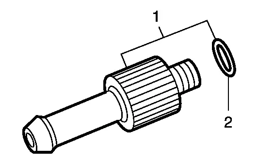
    Charging pipe set

  2. KV31103920*

    ( — )

    O-ring

A/T fluid changing and adjustment

( — )

(NI-52584)

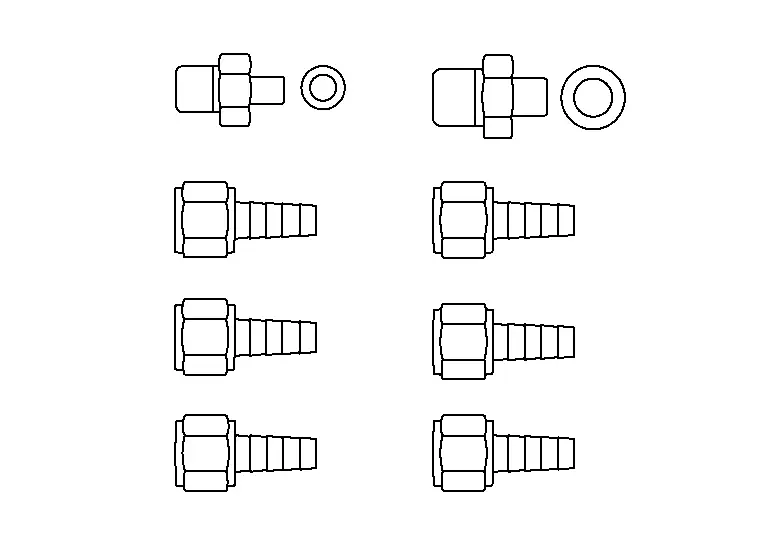
A/T stand pipe adapter kit
A/T fluid changing and adjustment

KV38107900

(NI-52469–1)

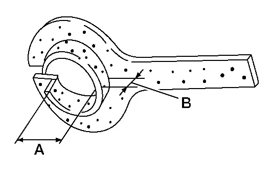
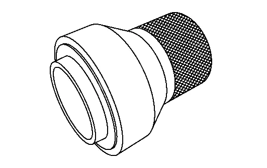
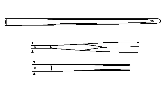
Differential side oil seal protector

Installing drive shaft

A: 32 mm (1.26 in) dia

B: Minimum 23 mm (0.91 in)

—

(NI-52982)

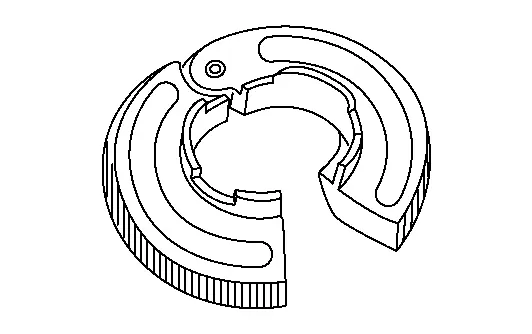
Lock nut chisel (Cape chisel)
Removing wheel hub lock nut

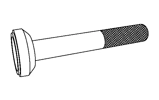
KV31103700

( — )

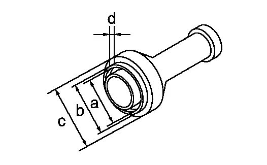
Drift

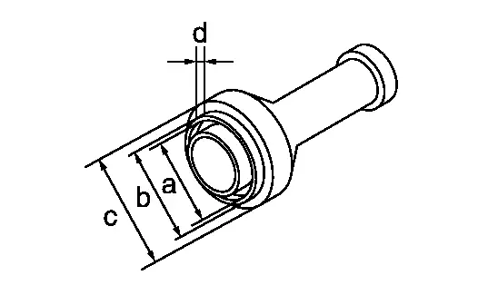
Differential side oil seal (Transaxle case side)

a: 53 mm (2.09 in) dia.

b: 57 mm (2.24 in) dia.

c: 70 mm (2.76 in) dia.

d: 8 mm (0.31 in) dia.

(NI-51001)

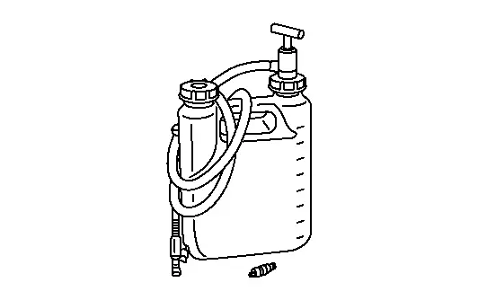
Transmission fill pump
Oil fill kit

—

(NI-53124)

Output seal installer
Installing differential side oil seal (LH)

—

(NI-53125)

Output seal installer
Installing differential side oil seal (RH)

—

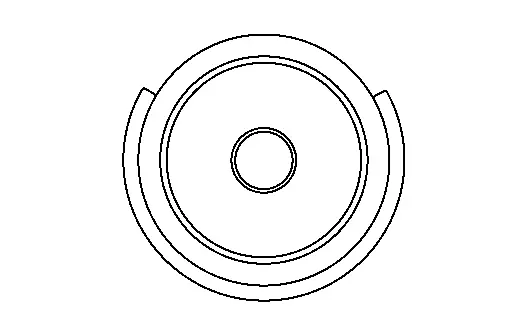
(NI-53126)

Input seal installer
Installing converter housing oil seal

*: The O-ring as a unit part is set as a SST.

Commercial Service Tools

Tool nameDescription
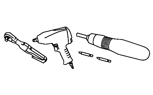
Power tool
Loosening nuts, screws and bolts
Drift

Installing differential side oil seal (Converter housing side)

a: 47mm (1.85 in) dia.

b: 51 mm (2.01 in) dia.

c: 70 mm (2.76 in) dia.

d: 8 mm (0.31 in) dia.
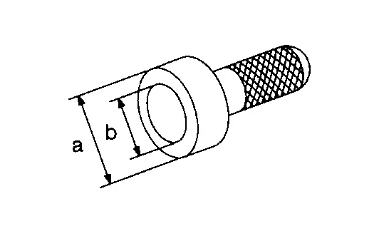
Drift

Installing converter housing oil seal

a: 65 mm (2.56 in) dia.

b: 60 mm (2.36 in) dia.
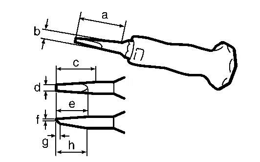
Lock nut crimp punch (Cold chisel)

Installing wheel hub lock nut

a: 5 mm (0.20 in)

b: 7 mm (0.28 in)
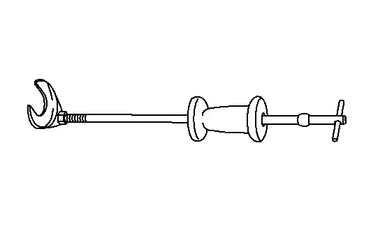
Drive shaft joint puller
Removing drive shaft
5/8" Disconnect tool
For removal of the A/T fluid cooler hoses.

Always Replace with New Parts

Never Reuse These PartsPart # PrefixFor additional information:
Hose clamp 31088F WATER HOSE EXPLODED VIEW
Differential side oil seal 38342P WATER OUTLET AND WATER PIPING EXPLODED VIEW
Converter housing oil seal 31110 TORQUE CONVERTER AND CONVERTER HOUSING OIL SEAL EXPLODED VIEW
O-ring — CONTROL VALVE EXPLODED VIEW
Wheel hub lock nut 40262 FRONT WHEEL HUB EXPLODED VIEW
Nut 40040B FRONT WHEEL HUB EXPLODED VIEW
O-ring 92471 COOLER PIPE AND HOSE EXPLODED VIEW
Gasket 20691 EXHAUST SYSTEM EXPLODED VIEW
Seal bearing 20695 EXHAUST SYSTEM EXPLODED VIEW
Bolt 20020B EXHAUST SYSTEM EXPLODED VIEW
Nut 20020A EXHAUST SYSTEM EXPLODED VIEW
Bolt 37010AA REAR PROPELLER SHAFT EXPLODED VIEW
Nut 37050B REAR PROPELLER SHAFT EXPLODED VIEW
Nut 54040B FRONT COIL SPRING AND STRUT EXPLODED VIEW
Nut 54060B FRONT STABILIZER EXPLODED VIEW
Bolt 14002B EXHAUST MANIFOLD AND THREE WAY CATALYST EXPLODED VIEW
Gasket 14036M EXHAUST MANIFOLD AND THREE WAY CATALYST EXPLODED VIEW

Symptom Diagnosis. System Symptom Nissan Pathfinder 2022

Symptom Table

The diagnostics item numbers show the sequence for inspection. Inspect in order from item 1.

Diagnostic itemReferenceSymptom
Poor performanceFunction trouble
Driving performanceStrange noiseGear does no changePoor shiftingPoor power transmission
Shift point is high in “D” position.Shift point is low in “D” position.Large shockJudderSlipSlip
When shifting gears
→“D” position→“R” positionDownshift when accelerator pedal is depressedUpshift when accelerator pedal is releasedLock-upIn “R” positionIn “N” positionIn “D” positionEngine at idleIn “D” positionIn “M” positionWhen shifting gearsWith selector lever in “D” position, acceleration is extremely poor.With selector lever in “R” position, acceleration is extremely poor.No creep at all.Extremely large creep.
Nissan Pathfinder Vehicle speed signal Diagnosis Procedure 2 2 2 2 1 1 1 1 2 1 1 1 1 2 3 3 3 3
Accelerator pedal position signal DTC Index 1 1 2 2 1 1 2 2 2 2 2 1 1 1 2 2 2 2
Engine speed signal DTC Index 1 1 1 1 1 1 1 1 1 1 1 1 1 1 1 1 1 1
Battery voltage Diagnosis Procedure 3 3 3 3
Electric shift selector DTC Index 1 1 1 1 2 3 3 3 3 1 1 1 1 1 1
Paddle shifters Diagnosis Procedure 1 1 1 1 3 3 3 3 3 1 1 3
Stop lamp switch Diagnosis Procedure 1 1 1 1 1 1 2 2 2 2 2 1 1 1 1 1 1 1
CAN communication Trouble Diagnosis Flow Chart 1 1 1 1 1 1 1 1 1 1 1 1 1 1 1 1 1 1
TCM Removal and Installation 2 2 2 2 2 2 2 3 3 3 3 1 1 1 1 1
  • Sensor unit (Dual speed sensor, A/T fluid temperautre sensor, Park position sensor)

  • Dog clutch A position sensor

  • Sensor unit: Removal and Installation

  • Dog clutch A positoin sensor: Removal and Installation

1 1 1 1 1 1 1 1 1 1 1 1 1 1 1 1 1 1
Control valve (Each pressure regulator, parking lock valve, parking lock actuator) Removal and Installation 1 1 1 1 1 1 1 1 1 1 1 1 1 1 1 1 1 1
Transaxle assembly (Dog clutch F position sensor, Oil pump, Each clutch/brake, Planetary gear, Parking component) Removal and Installation 3 3 3 3 3 3 3 3 3 3 3 2 2 3 3 3 3 3
Torque converter Disassembly 3 3 3 3 3 3 3 3 3 3 3 2 2 3 3 3 3 3
Insufficient shift control learning Refer to following. 3 3 1 1 1 1 1 2 2 1 3 3 3 3

Shifting control learning

This transmission learns to achieve optimum shifting by repeatedly shifting gears up and down while driving.

When a shift shock or lag occurs during driving, the following driving is performed to make the transmission learn shift control.

  1. Reproduce the phenomenon complained by the customer.

  2. The same conditions as the complaint phenomenon (gear position / engine speed / accelerator opening angle) are repeated about 10 times.

Periodic Maintenance. A/t Fluid Nissan Pathfinder SUV

Inspection

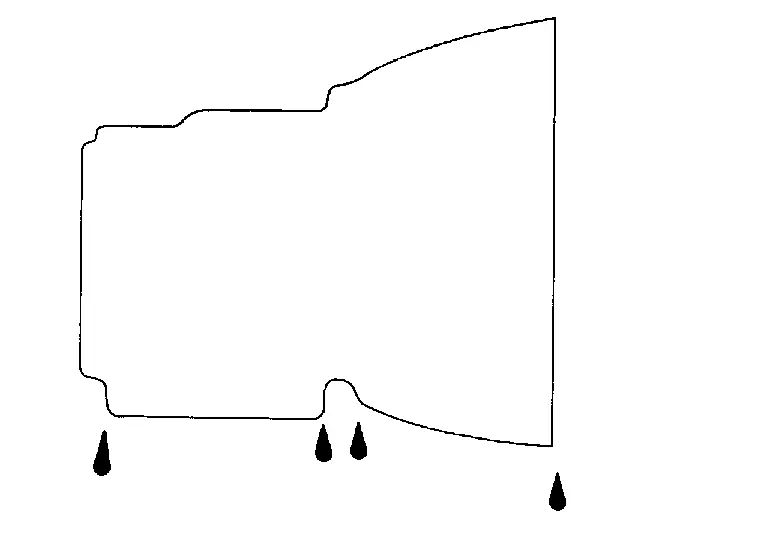
FLUID LEAKAGE

  • Check transaxle surrounding area (oil seal and plug etc.) for fluid leakage.

  • If anything is found, repair or replace damaged parts and adjust A/T fluid level. Refer to Adjustment.
Replacement

A/T fluid : Refer to General Specification.
Fluid capacity : Refer to General Specification.

Select “Data Monitor” in “TRANSMISSION” using CONSULT.

Select “FLUID TEMP” and confirm that the A/T fluid temperature is between 35 °C and 45 °C.

Check that the selector lever is in the “P” position, then completely engage the parking brake.

Lift up the Nissan Pathfinder vehicle.

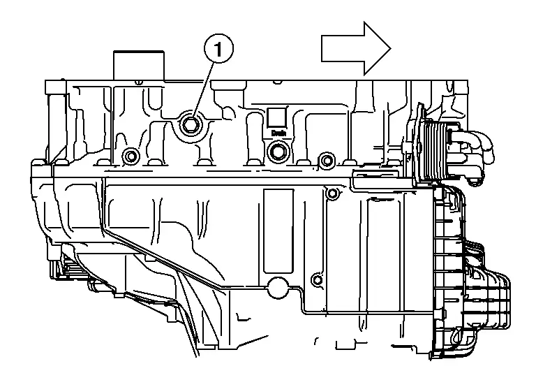
Remove the drain plug (1) and drain the A/T fluid from A/T case.
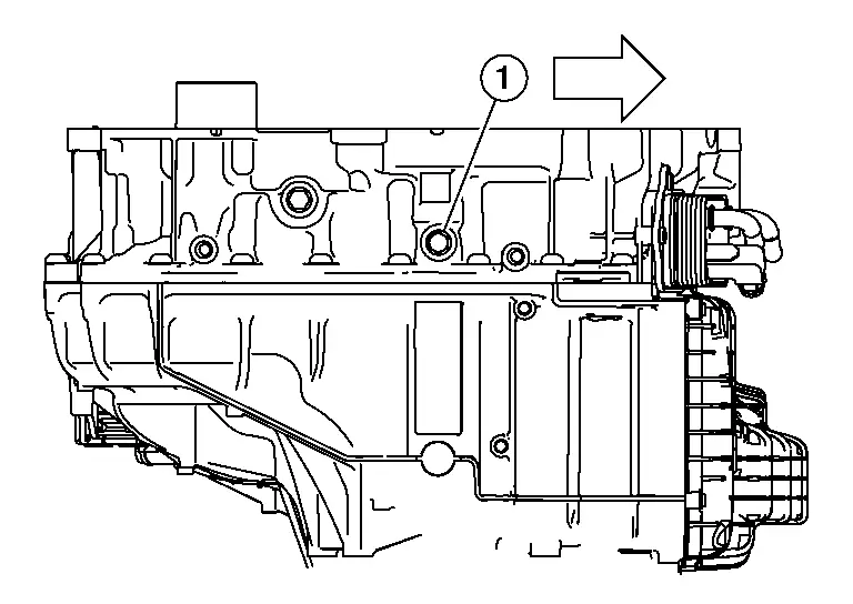
: Nissan Pathfinder Vehicle front

Install the drain plug to specified torque. Refer to Exploded View.

Remove the fill plug (1).
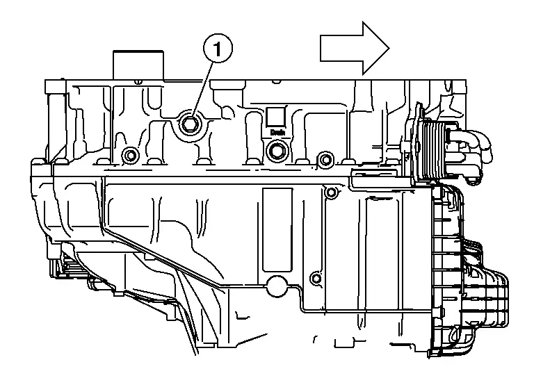
: Nissan Pathfinder Vehicle front

Install the charging pipe set (A/T stand pipe adapter kit) KV311039S0 (NI-52584) into the overflow plug hole.

Install the ATF changer hose to the charging pipe.

Fill approximately 7 liter (7-1/2 US qt, 6-1/4 lmp qt) of the A/T fluid.

Remove the ATF changer hose and charging pipe, then install and finger tighten the fill plug.

Start the engine.

Park the Nissan Pathfinder vehicle on a level surface with the engine running and parking brake set.

Using CONSULT-III plus, ensure that the A/T fluid temperature is between 95°F to 113°F (35°C to 45°C).

With Nissan Pathfinder vehicle in PARK and A/T fluid temperature in correct range, let engine run at 2000 rpm for about 10 seconds.

Shift the transmission into REVERSE for 10 seconds.

Shift the transmission into DRIVE for 10 seconds.

Shift the transmission into 1st for 10 seconds.

Shift the transmission into 2nd for 10 seconds.

Shift the transmission into 3rd for 10 seconds.

Shift the transmission into 4th for 10 seconds.

Shift the transmission into NEUTRAL until wheels come to a complete stop.

Shift the transmission into PARK.

Lift up the Nissan Pathfinder vehicle.

Remove the fill plug (1).
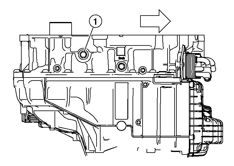
: Nissan Pathfinder Vehicle front

If A/T fluid flows out of fill hole, let A/T fluid flow out until flow is reduced to a thin stream and then install fill plug and tighten to specification. If A/T fluid does not run out of fill hole repeat steps 1–18 adding small quantities of A/T fluid at a time.

Adjustment

A/T fluid : Refer to General Specification.
Fluid capacity : Refer to General Specification.

Remove the fill plug (1).

: Nissan Pathfinder Vehicle front

Install the charging pipe set (A/T stand pipe adapter kit) KV311039S0 (NI-52584) into the overflow plug hole.

Install the ATF changer hose to the charging pipe.

Fill A/T with small amount of the A/T fluid.

Remove the ATF changer hose and charging pipe, then install and finger tighten the fill plug.

Start the engine.

Park the Nissan Pathfinder vehicle on a level surface with the engine running and parking brake set.

Using CONSULT-III plus, ensure that the A/T fluid temperature is between 95°F to 113°F (35°C to 45°C).

With Nissan Pathfinder vehicle in PARK and A/T fluid temperature in correct range, let engine run at 2000 rpm for about 10 seconds.

Shift the transmission into REVERSE for 10 seconds.

Shift the transmission into DRIVE for 10 seconds.

Shift the transmission into 1st for 10 seconds.

Shift the transmission into 2nd for 10 seconds.

Shift the transmission into 3rd for 10 seconds.

Shift the transmission into 4th for 10 seconds.

Shift the transmission into NEUTRAL until wheels come to a complete stop.

Shift the transmission into PARK.

Lift up the Nissan Pathfinder vehicle.

Remove the fill plug (1).

: Nissan Pathfinder Vehicle front

If A/T fluid flows out of fill hole, let A/T fluid flow out until flow is reduced to a thin stream and then install fill plug and tighten to specification. If A/T fluid does not run out of fill hole repeat steps 1–18 adding small quantities of A/T fluid at a time.

Unit Removal and Installation. Transaxle Assembly ➤ Nissan Pathfinder SUV

Unit Disassembly and Assembly. Torque Converter and Converter Housing Oil Seal Nissan Pathfinder

Exploded View
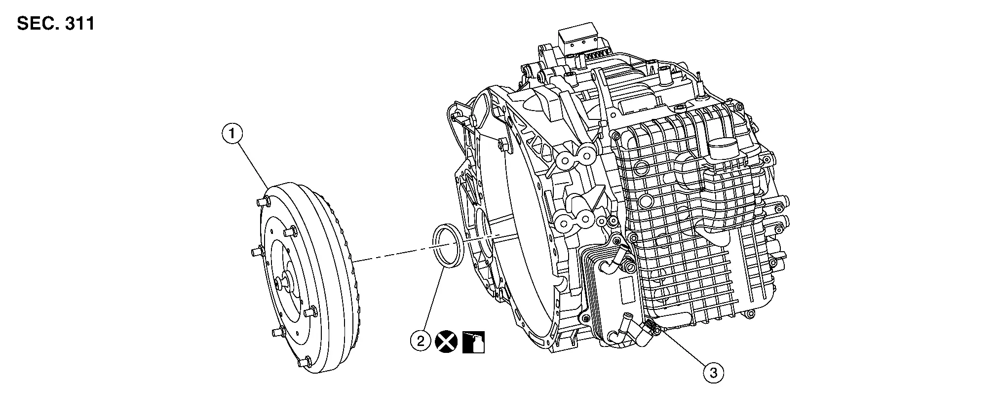
1. Torque converter 2. Converter housing oil seal 3. Transaxle assembly

Disassembly

Never Reuse These PartsPart # PrefixFor additional information:
Converter housing oil seal 31110 Exploded View

Remove transaxle assembly. Refer to Removal and Installation.

Remove torque converter from transaxle assembly.

Remove converter housing oil seal using suitable tool.

Assembly

Assembly is in the reverse order of disassembly.

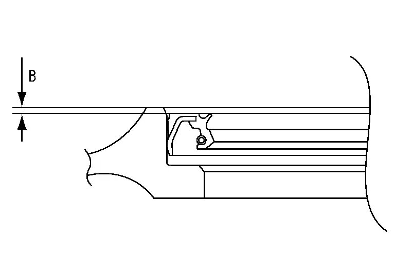
  • Drive converter housing oil seal (1) evenly using Tool (A) until converter housing oil seal is flush with transaxle assembly (2).
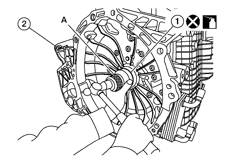
    Tool (A) : — (J-53126)

    Unit: mm (in)

    Dimension (B) 1.0 ± 0.5 (0.039 ± 0.020)
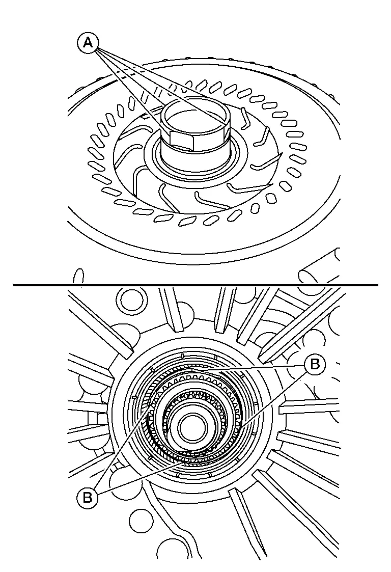
  • Align grooves (A) of the torque converter to the drive sprocket hole gooves (B) on the transaxle assembly side.
Inspection

INSPECTION AFTER INSTALLATION

  • After inserting torque converter to the A/T, check dimension (A) within the reference value limit.
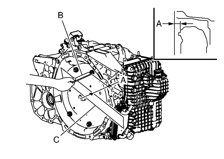
    B : Scale
    C : Straightedge
    Dimension (A) : Refer to Torque Converter.

Service Data and Specifications (SDS) Nissan Pathfinder

General Specification

Applied model Engine VQ35DD
Axle 2WD/4WD
Transmission model GE9F01A
Transmission gear ratio 1st 4.713
2nd 2.842
3rd 1.909
4th 1.382
5th 1.000
6th 0.808
7th 0.699
8th 0.580
9th 0.480
Reverse 3.830
Final gear 4.334
A/T fluid Recommended fluid Nissan Matic R*1
Capacity (Approx.) Without Tow Package With Tow Package
7.2 L (7-5/8 US qt, 6-3/8 lmp qt)*2 7.5 L (7-7/8 US qt, 6-5/8 lmp qt)*2

*1: Always use the designated stock of A/T fluid. Using or mixing A/T fluid other than the designated stock or using it incorrectly could result in an inability to achieve original performance, or may cause a serious accident.

*2: The A/T fluid amount is only a guide.

Vehicle Speed at Which Gear Shifting Occurs

STANDARD/SPORT/ECO

Unit: km/h (MPH)

Gear positionAccelerator pedal
100%50%
D1 → D2 41 – 46 (25 – 29) 26 – 36 (16 – 22)
D2 → D3 70– 75 (43– 47) 45 – 66 (28 – 41)
D3 → D4 103– 108 (64– 67) 70 – 108 (43 – 67)
D4 → D5 143– 148 (89– 92) 97 – 148 (60 – 92)
D5 → D6 187– 192 (116– 119) 127 – 193 (79 – 120)
D6 → D7 232– 237 (144– 147) 151 – 237 (94 – 147)
D7 → D8 262 – 267 (163 – 166) 171 – 267 (106 – 166)
D8 → D9 262 – 267 (163– 166) 198 – 267 (123 – 166)
D9 → D8 234 – 307 (145 – 191) 178 – 248 (111 – 154)
D8 → D7 243 – 255 (151 – 158) 155 – 248 (96 – 154)
D7 → D6 209 – 221 (130 – 137) 133 – 184 (83 – 114)
D6 → D5 168 – 179 (104 – 111) 108 – 148 (67 – 92)
D5 → D4 121 – 130 (75 – 81) 71 – 109 (44 – 68)
D4 → D3 93 – 97 (58 – 60) 53 – 73 (33 – 45)
D3 → D2 53 – 64 (33 – 40) 36 – 46 (22 – 29)
D2 → D1 16 – 35 (10 – 22) 1 – 20 (1 – 12)

Torque Converter

Unit: mm (in)

Distance between the converter housing and torque 17.4 - 17.9 (0.685 - 0.705)