Transmission & Driveline :: Transaxle & Transmission

Basic Inspection

In this manual: Transmission & Driveline :: Transaxle & Transmission
General Information — 8Engine :: Engine Mechanical — 19Engine Lubrication System - Precautions. Preparation — 1Engine Lubrication System - Lubrication System (System Description). Engine Oil Pressure (Basic Inspection). Service Data and Specifications (SDS) — 1Engine Cooling System - Precautions. Preparation. Service Data and Specifications (SDS) — 1Engine Cooling System - Engine Coolant — 1Engine Control System - System Description — 1System Description - Component Parts ++ — 1System Description - System ++ — 1Engine Control System - Ecu Diagnosis Information — 1Ecu Diagnosis Information - Ecm ++ — 1Engine Control System - Basic Inspection — 1Basic Inspection - Diagnosis and Repair Workflow ++ — 1Basic Inspection - Basic Inspection ++ — 1Basic Inspection - Additional Service When Replacing Ecm ++ — 1Basic Inspection - Fuel Pressure Check ++ — 1Basic Inspection - How to Set Srt Code ++ — 1Basic Inspection - How to Erase Permanent Dtc ++ — 1Engine Control System - Dtc/circuit Diagnosis — 1Engine Control System - Symptom Diagnosis — 1Engine Control System - Periodic Maintenance — 1Engine Control System - Removal and Installation — 1Fuel System - Precautions. Preparation. Service Data and Specifications (SDS) — 1Fuel System - Fuel System (Periodic Maintenance). Fuel Level Sensor Unit (Disassembly and Assembly) — 1Exhaust System - Precautions. Preparation — 1Exhaust System - Exhaust System (Periodic Maintenance). Exhaust System (Removal and Installation) — 1Starting System - Precautions. Preparation. Starter Motor (Service Data and Specifications (sds)) — 1Starting System - Diagnosis and Repair Work Flow — 1Starting System - Starting System (Symptom Diagnosis). Starter Motor (Removal and Installation) — 1Accelerator Control System - Precautions. Service Data and Specifications (SDS) — 1Accelerator Control System - Accelerator Pedal Assembly — 1Transmission & Driveline :: Transaxle & Transmission — 21Driveline - System Description — 1Transfer: Ty92b - Ecu Diagnosis Information. Awd Control Unit ++ — 1Driveline - Basic Inspection — 1Driveline - Dtc/circuit Diagnosis — 1Driveline - Symptom Diagnosis — 1Driveline - Removal and Installation — 1Transfer: Ty92b - Unit Removal and Installation. Transfer Assembly ++ — 1Driveline - Unit Disassembly and Assembly — 1Driveline - Basic Inspection — 1Driveline - Removal and Installation — 1Driveline - Unit Disassembly and Assembly — 1Front Axle - Precautions. Preparation — 1Front Axle - Noise, Vibration and Harshness (nvh) Troubleshooting (Symptom Diagnosis). Service Data and Specifications (SDS) — 1Front Axle - Front Drive Shaft Boot — 1Front Axle - Front Drive Shaft — 1Rear Axle - Precautions. Preparation. Service Data and Specifications (SDS) — 1Rear Axle - Noise, Vibration and Harshness (nvh) Troubleshooting — 1Rear Axle - Rear Drive Shaft — 1Suspension :: Front Suspension — 7Rear Suspension - Precautions. Preparation — 1Rear Suspension - Noise, Vibration and Harshness (nvh) Troubleshooting (Symptom Diagnosis). Service Data and Specifications (SDS) — 1Rear Suspension - Rear Suspension Assembly — 1Road Wheels & Tires - Precautions — 1Road Wheels & Tires - Preparation. Bcm (Ecu Diagnosis Information). Service Data and Specifications (SDS) — 1Road Wheels & Tires - System — 1Brakes :: Brake System — 9Parking Brake System - Precautions. Preparation — 1Parking Brake System - System — 1Vdc/tcs/abs - Precautions ++ — 1Brake Control System - System Description — 1System Description - Component Parts ++ — 1System Description - System ++ — 1Brake Control System - Basic Inspection — 1Brake Control System - Symptom Diagnosis — 1Brake Control System - Removal and Installation — 1Brake Control System - System Description — 1Brake Control System - Dtc/circuit Diagnosis — 1Brake Control System - Removal and Installation — 1Brake Control System - System Description — 1Brake Control System - Basic Inspection — 1Brake Control System - Symptom Diagnosis — 1Brake Control System - System Description — 1Brake Control System - Basic Inspection — 1Brake Control System - Symptom Diagnosis — 1Steering :: Steering System — 9Steering Control System - Precautions — 1Steering Control System - System — 1Steering Control System - Eps Control Unit (Ecu Diagnosis Information. Removal and Installation) — 1Restraints :: Seat Belt — 7Srs Air Bag - Precautions. Preparation — 1Srs Air Bag - Collision Diagnosis — 1Srs Air Bag - Occupant Classification System — 1Srs Air Bag Control System - Precautions — 1Srs Air Bag Control System - System — 1Srs Air Bag Control System - Diagnosis Sensor Unit — 1Srs Air Bag Control System - Inspection and Adjustment — 1Ventilation, Heater & Air Conditioner :: Ventilation System — 6Heater & Air Conditioning System - Precautions — 1Heater & Air Conditioning System - Preparation — 1Heater & Air Conditioning System - Component Parts — 1Heater & Air Conditioning System - Diagnosis and Repair Work Flow — 1Heater & Air Conditioning System - Compressor — 1Heater & Air Conditioning System - Cooler Pipe and Hose — 1Heater & Air Conditioning System - Condenser. Condenser — 1Heater & Air Conditioning System - Heating and Cooling Unit Assembly — 1Heater & Air Conditioning System - Service Data and Specifications (SDS) — 1Heater & Air Conditioning Control System - System Description — 1System Description - Component Parts ++ — 1System Description - System ++ — 1System Description - Operation ++ — 1Heater & Air Conditioning Control System - Ecu Diagnosis Information — 1Heater & Air Conditioning Control System - Basic Inspection — 1Heater & Air Conditioning Control System - Dtc/circuit Diagnosis — 1Heater & Air Conditioning Control System - Symptom Diagnosis — 1Heater & Air Conditioning Control System - Removal and Installation — 1Body Interior :: Interior — 8Instrument Panel - Precautions. Preparation. Clip List — 1Instrument Panel - Squeak and Rattle Trouble Diagnoses — 1Instrument Panel - Cluster Lid C — 1Seat - Precautions — 1Seat - Preparation. Clip List — 1Seat - Component Parts — 1Seat - System — 1Seat - Diagnosis and Repair Work Flow — 1Seat - Front Seat — 1Seat - Second Row Seats — 1Seat - Third Row Seats — 1Seat - Front Seat — 1Seat - Second Row Seat — 1Seat - Third Row Seat — 1Automatic Drive Positioner - Precautions. Preparation — 1Automatic Drive Positioner - System — 1Automatic Drive Positioner - Diagnosis and Repair Work Flow — 1Automatic Drive Positioner - Inspection and Adjustment — 1Body Exterior, Doors, Roof & Vehicle Security :: Door & Lock — 38Security Control System - Precautions — 1Security Control System - System — 1Security Control System - Ecm, Bcm, Intelligent Key Unit, Ipdm E/r — 1Security Control System - Vehicle Security System Cannot Be Set — 1Glass & Window System - Precautions. Preparation — 1Glass & Window System - Squeak and Rattle Trouble Diagnoses — 1Power Window Control System - Precautions. Preparation — 1Power Window Control System - Power Supply and Ground Circuit — 1Power Window Control System - Power Window Motor Circuit — 1Power Window Control System - Front Power Window Rh Alone Does Not Operate — 1Power Window Control System - Rear Lh Side Power Window Alone Does Not Operate — 1Power Window Control System - Rear Rh Side Power Window Alone Does Not Operate — 1Roof - Precautions. Preparation — 1Roof - Power Supply and Ground Circuit — 1Roof - Moonroof Switch Assembly — 1Roof - Lin Communication Circuit — 1Roof - Auto Operation Does Not Operate — 1Roof - Anti-Pinch Function Does Not Operate — 1Exterior - Precautions. Preparation. Clip List (Preparation) — 1Exterior - Squeak and Rattle Trouble Diagnoses — 1Exterior - Fender Protector — 1Exterior - Over Fender — 1Exterior - Under Cover — 1Exterior - Roof Side Rail — 1Body Repair - Service Information — 1Service Information - Sheet Metal Work ++ — 1Service Information - Body Welding and Precautions ++ — 1Service Information - Safety and Health ++ — 1Service Information - Repairing Procedures and Precautions ++ — 1Body Repair - Precaution — 1Body Repair - Preparation — 1Body Repair - Removal and Installation — 1Driver Controls :: Mirrors — 8Exterior Lighting System - System Description — 1System Description - Component Parts ++ — 1Exterior Lighting System - Basic Inspection — 1Exterior Lighting System - Dtc/circuit Diagnosis — 1Exterior Lighting System - Symptom Diagnosis — 1Exterior Lighting System - Periodic Maintenance — 1Exterior Lighting System - Removal and Installation — 1Interior Lighting System - Precautions. Preparation — 1Interior Lighting System - Component Parts. Interior Lighting System — 1Interior Lighting System - System — 1Interior Lighting System - Diagnosis and Repair Work Flow — 1Interior Lighting System - Interior Lighting System Symptoms (Symptom Diagnosis). Bcm (Ecu Diagnosis Information). Service Data and Specifications (SDS) — 1Interior Lighting System - Foot Lamp — 1Wiper & Washer - Precautions — 1Wiper & Washer - Preparation. Bcm, Ipdm E/r (Ecu Diagnosis Information). Service Data and Specifications (SDS) — 1Wiper & Washer - System — 1Wiper & Washer - Diagnosis and Repair Work Flow — 1Defogger - Precautions. Bcm, A/c Auto Amp. (Ecu Diagnosis Information) — 1Defogger - Diagnosis and Repair Work Flow — 1Horn - Precautions — 1Electrical & Power Control :: Power Outlet — 13Body Control System - Precautions. Preparation — 1Body Control System - Component Parts — 1Body Control System - System — 1Body Control System - Diagnosis System (bcm) — 1Body Control System - Bcm — 1Lan System - System Description — 1Lan System - System Description — 1Lan System - Dtc/circuit Diagnosis — 1Lan System - System Description — 1Lan System - Dtc/circuit Diagnosis — 1Power Control System - System Description — 1Power Control System - Basic Inspection — 1Power Control System - Dtc/circuit Diagnosis — 1Power Control System - System Description — 1Power Control System - Basic Inspection — 1Power Control System - Dtc/circuit Diagnosis — 1Power Control System - Removal and Installation — 1Charging System - Precautions. Preparation. Ecm, Ipdm E/r (Ecu Diagnosis Information) — 1Charging System - Diagnosis and Repair Work Flow — 1Charging System - Charging System (Symptom Diagnosis). Generator (Removal and Installation). Service Data and Specifications (SDS) — 1Power Supply, Ground & Circuit Elements - Precautions. Preparation. Service Data and Specifications (SDS) — 1Driver Information & Multimedia :: Meter, Warning Lamp & Indicator — 25Warning Chime System - Application Notice (How to Use This Manual). Precautions — 1Warning Chime System - System — 1Warning Chime System - Diagnosis System (combination Meter) — 1Warning Chime System - Bcm, Combination Meter (Ecu Diagnosis Information). Diagnosis and Repair Work Flow (Basic Inspection) — 1Sonar System - Precautions. Preparation — 1Sonar System - Sonar Control Unit — 1Dtc/circuit Diagnosis - B2720 Corner Sensor [rl] ++ — 1Audio, Visual & Navigation System - System Description — 1System Description - Component Parts ++ — 1System Description - System ++ — 1Audio, Visual & Navigation System - Ecu Diagnosis Information — 1Audio, Visual & Navigation System - Basic Inspection — 1Audio, Visual & Navigation System - Dtc/circuit Diagnosis — 1Dtc/circuit Diagnosis - Multi Av (av Control Unit) ++ — 1Audio, Visual & Navigation System - Symptom Diagnosis — 1Symptom Diagnosis - Multi Av System ++ — 1Audio, Visual & Navigation System - Removal and Installation — 1Audio, Visual & Navigation System - System Description — 1Audio, Visual & Navigation System - Ecu Diagnosis Information — 1Audio, Visual & Navigation System - Basic Inspection — 1Audio, Visual & Navigation System - Dtc/circuit Diagnosis — 1Audio, Visual & Navigation System - Symptom Diagnosis — 1Audio, Visual & Navigation System - Removal and Installation — 1Audio, Visual & Navigation System - System Description — 1Audio, Visual & Navigation System - Basic Inspection — 1Audio, Visual & Navigation System - Dtc/circuit Diagnosis — 1Audio, Visual & Navigation System - Symptom Diagnosis — 1Audio, Visual & Navigation System - Removal and Installation — 1Audio, Visual & Navigation System - System Description — 1Audio, Visual & Navigation System - Basic Inspection — 1Audio, Visual & Navigation System - Dtc/circuit Diagnosis — 1Audio, Visual & Navigation System - Symptom Diagnosis — 1Audio, Visual & Navigation System - Removal and Installation — 1Cruise Control & Driver Assistance :: Cruise Control System — 17Driver Assistance System - System Description — 1Driver Assistance System - Basic Inspection — 1Driver Assistance System - Dtc/circuit Diagnosis — 1Driver Assistance System - System Description — 1System Description - Component Parts ++ — 1System Description - System ++ — 1System Description - Operation ++ — 1System Description - Handling Precaution ++ — 1Driver Assistance System - Ecu Diagnosis Information — 1Driver Assistance System - Basic Inspection — 1Basic Inspection - Distance Sensor Alignment ++ — 1Basic Inspection - Camera Aiming Adjustment ++ — 1Basic Inspection - Action Test ++ — 1Driver Assistance System - Dtc/circuit Diagnosis — 1Dtc/circuit Diagnosis - Laser/radar (distance Sensor) ++ — 1Dtc/circuit Diagnosis - Lane Camera (front Camera Unit) ++ — 1Driver Assistance System - Symptom Diagnosis — 1Driver Assistance System - Removal and Installation — 1Driver Assistance System - System Description — 1System Description - System ++ — 1Driver Assistance System - Basic Inspection — 1Driver Assistance System - Dtc/circuit Diagnosis — 1Drive Mode System - Precautions — 1Drive Mode System - Component Parts. Drive Mode System — 1Drive Mode System - System — 1Drive Mode System - Diagnosis and Repair Work Flow — 1Drive Mode System - Drive Mode Select Switch Circuit — 1Maintenance - Precautions. Preparation — 1Maintenance - General Maintenance — 1Maintenance - Periodic Maintenance — 1Maintenance - Recommended Fluids and Lubricants — 1Maintenance - Engine Maintenance — 1Maintenance - Chassis and Body Maintenance — 1Engine Lubrication System - Periodic Maintenance — 1Engine Lubrication System - Removal and Installation — 1Engine Cooling System - System Description — 1Engine Cooling System - Removal and Installation — 1Engine Control System - Vq35dd — 1Fuel System - Removal and Installation — 1Starting System - System Description — 1Starting System - Dtc/circuit Diagnosis — 1Driveline - Transfer: Ty92b — 1Driveline - Rear Propeller Shaft: 3fcj-Cvj — 1Driveline - Rear Final Drive: R145 — 1Front Axle - Periodic Maintenance — 1Front Axle - Removal and Installation — 1Rear Axle - Periodic Maintenance — 1Rear Axle - Removal and Installation — 1Rear Suspension - Removal and Installation — 1Road Wheels & Tires - System Description — 1Road Wheels & Tires - Basic Inspection — 1Road Wheels & Tires - Dtc/circuit Diagnosis — 1Road Wheels & Tires - Symptom Diagnosis — 1Road Wheels & Tires - Periodic Maintenance — 1Road Wheels & Tires - Removal and Installation — 1Parking Brake System - System Description — 1Parking Brake System - Basic Inspection — 1Parking Brake System - Dtc/circuit Diagnosis — 1Parking Brake System - Symptom Diagnosis — 1Parking Brake System - Removal and Installation — 1Brake Control System - Vdc/tcs/abs — 1Brake Control System - Automatic Brake Hold — 1Brake Control System - Automatic Emergency Braking — 1Brake Control System - Rear Automatic Braking — 1Steering Control System - System Description — 1Steering Control System - Basic Inspection — 1Steering Control System - Dtc/circuit Diagnosis — 1Steering Control System - Symptom Diagnosis — 1Srs Air Bag - Removal and Installation — 1Srs Air Bag Control System - System Description — 1Srs Air Bag Control System - Basic Inspection — 1Srs Air Bag Control System - Symptom Diagnosis — 1Heater & Air Conditioning System - Symptom Diagnosis — 1Heater & Air Conditioning System - Periodic Maintenance — 1Heater & Air Conditioning Control System - Automatic Air Conditioning — 1Instrument Panel - Removal and Installation — 1Instrument Panel - Unit Disassembly and Assembly — 1Seat - Ecu Diagnosis Information — 1Seat - Dtc/circuit Diagnosis — 1Seat - Symptom Diagnosis — 1Automatic Drive Positioner - System Description — 1Automatic Drive Positioner - Ecu Diagnosis Information — 1Automatic Drive Positioner - Dtc/circuit Diagnosis — 1Automatic Drive Positioner - Symptom Diagnosis — 1Automatic Drive Positioner - Removal and Installation — 1Security Control System - System Description — 1Security Control System - Basic Inspection — 1Security Control System - Dtc/circuit Diagnosis — 1Security Control System - Symptom Diagnosis — 1Security Control System - Removal and Installation — 1Glass & Window System - Removal and Installation — 1Power Window Control System - System Description — 1Power Window Control System - Ecu Diagnosis Information — 1Power Window Control System - Basic Inspection — 1Power Window Control System - Dtc/circuit Diagnosis — 1Power Window Control System - Symptom Diagnosis — 1Power Window Control System - Removal and Installation — 1Roof - System Description — 1Roof - Ecu Diagnosis Information — 1Roof - Basic Inspection — 1Roof - Dtc/circuit Diagnosis — 1Roof - Symptom Diagnosis — 1Roof - Removal and Installation — 1Exterior - System Description — 1Exterior - Removal and Installation — 1Body Repair - Repair Information — 1Exterior Lighting System - Led Headlamp — 1Interior Lighting System - Dtc/circuit Diagnosis — 1Interior Lighting System - Removal and Installation — 1Wiper & Washer - System Description — 1Wiper & Washer - Dtc/circuit Diagnosis — 1Wiper & Washer - Symptom Diagnosis — 1Wiper & Washer - Removal and Installation — 1Defogger - System Description — 1Defogger - Dtc/circuit Diagnosis — 1Defogger - Symptom Diagnosis — 1Defogger - Removal and Installation — 1Horn - Removal and Installation — 1Body Control System - Basic Inspection — 1Body Control System - Dtc/circuit Diagnosis — 1Body Control System - Symptom Diagnosis — 1Body Control System - Removal and Installation — 1Lan System - Can Fundamental — 1Lan System - Can — 1Lan System - Can Gateway — 1Power Control System - Ipdm E/r — 1Power Control System - Power Distribution System — 1Charging System - System Description — 1Charging System - Dtc/circuit Diagnosis — 1Power Supply, Ground & Circuit Elements - System Description — 1Power Supply, Ground & Circuit Elements - Basic Inspection — 1Power Supply, Ground & Circuit Elements - Removal and Installation — 1Warning Chime System - System Description — 1Warning Chime System - Dtc/circuit Diagnosis — 1Warning Chime System - Symptom Diagnosis — 1Sonar System - System Description — 1Sonar System - Basic Inspection — 1Sonar System - Dtc/circuit Diagnosis — 1Sonar System - Symptom Diagnosis — 1Sonar System - Removal and Installation — 1Audio, Visual & Navigation System - Nissanconnect — 1Audio, Visual & Navigation System - Intelligent Around View Monitor System — 1Audio, Visual & Navigation System - Rear View Monitor System — 1Audio, Visual & Navigation System - Telematics System — 1Driver Assistance System - Adas Control Unit 2 — 1Driver Assistance System - Driver Assistance System — 1Driver Assistance System - Chassis Control — 1Drive Mode System - Removal and Installation — 1Dtc/circuit Diagnosis (C053c Wheel Speed Sensor ... U2141 Can Comm Circuit) — 1Dtc/circuit Diagnosis (P0011 Intake Valve Timing Control ... P0111 Iat Sensor) — 1Dtc/circuit Diagnosis (P0116 Engine Coolant Temperature Sensor ... P025b Fuel Pump Module a) — 1Dtc/circuit Diagnosis (P026b Injection Timing ... P0420 Three Way Catalyst Function) — 1Dtc/circuit Diagnosis (P0441 Evap Control System ... P0524 Engine Oil Pressure) — 1Dtc/circuit Diagnosis (P0532 A/c Refrigerant Pressure Sensor ... P064d Ecm) — 1Dtc/circuit Diagnosis (P06da Engine Oil Pressure Control Solenoid Valve ... P1217 Engine Over Temperature) — 1Dtc/circuit Diagnosis (P1220 Fuel Pump Control Module (fpcm) ... P1574 Ascd Vehicle Speed Sensor) — 1Dtc/circuit Diagnosis (P1575 Brake Switch ... P2101 Electric Throttle Control Function) — 1Dtc/circuit Diagnosis (P2118 Throttle Control Motor ... P34ac Electric Intake Valve Timing Control Actuator) — 1Dtc/circuit Diagnosis (Active Grille Shutter ... High Pressure Fuel Pump) — 1Dtc/circuit Diagnosis (Ignition Signal ... Variable Induction Air System) — 14012 C1040 Emergency Brake — 14013 C106a Wheel Sensor — 14014 C1078-55 Not Configuration — 14015 C10b4-98 Overheat — 14016 B1001 Lap Pre-Tensioner Lh — 14017 B0001 Driver Air Bag Module — 14018 B100e Knee Air Bag Module Rh — 14019 B142x Collision Detection — 1Dtc/circuit Diagnosis (B20c7-11 A/c Clutch ... B24a6-11 in-Vehicle Sensor) — 1Dtc/circuit Diagnosis (B24a6-15 in-Vehicle Sensor ... U2140-87 Can Comm Err (ecm)) — 1Dtc/circuit Diagnosis (C1f00-1c Control Unit ... C1f04-61 Brake Sw/stop Lamp Sw) — 1Dtc/circuit Diagnosis (C1f05-49 Front Camera Unit ... C1f70-87 Ethernet Circuit) — 1
65steps
~395min
5/5difficulty
1special tools
Done 0 of 65
  • Diagnosis and Repair Work Flow
  • Additional Service When Replacing Tcm
  • Additional Service When Replacing Transaxle Assembly
  • Additional Service When Replacing Control Valve
  • Dog Clutch Position Sensor Calibration
  • Learning of Solenoid Characteristic
  • A/t Clutch Touch Point Learning
  • Mac Key Writing
  • A/t Fluid Cooler System
  • A/t Position
  • How to Erase Permanent Dtc

Diagnosis and Repair Work Flow Nissan Pathfinder SUV

Work Flow

OBTAIN INFORMATION ABOUT SYMPTOM

Refer to Diagnostic Work Sheet and interview the customer to obtain the malfunction information (conditions and environment when the malfunction occurred) as much as possible when the customer brings in the Nissan Pathfinder vehicle.

>>

GO TO 2.

CHECK DTC

  1. Before checking the malfunction, check whether any DTC exists.

  2. If DTC exists, perform the following operations.

    • Record the DTC and freeze frame data. (Print out the data using CONSULT and affix them to the Work Order Sheet.)

    • Erase DTCs.

    • Check the relationship between the cause that is clarified with DTC and the malfunction information described by the customer. Symptom Table is effective.

Do malfunction information and DTC exists?

Malfunction information and DTC exists. >>

GO TO 3.

Malfunction information exists, but no DTC. >>

GO TO 4.

No malfunction information, but DTC exists.>>

GO TO 5.

REPRODUCE MALFUNCTION SYMPTOM

Check any malfunction described by a customer, except those with DTC on the Nissan Pathfinder vehicle.

Also investigate whether the symptom is a fail-safe or normal operation. Refer to Fail-safe.

When a malfunction symptom is reproduced, the question sheet is effective. Refer to Diagnostic Work Sheet.

Verify the relationship between the symptom and the conditions in which the malfunction described by the customer occurs.

>>

GO TO 5.

REPRODUCE MALFUNCTION SYMPTOM

Check the malfunction described by the customer on the Nissan Pathfinder vehicle.

Also investigate whether the symptom is a fail-safe or normal operation. Refer to Fail-safe.

When a malfunction symptom is reproduced, the question sheet is effective. Refer to Diagnostic Work Sheet.

Verify the relationship between the symptom and the conditions in which the malfunction described by the customer occurs.

>>

GO TO 6.

PERFORM “DTC CONFIRMATION PROCEDURE”

Perform “DTC CONFIRMATION PROCEDURE” of the appropriate DTC to check if DTC is detected again.

Refer to DTC Inspection Priority Chart when multiple DTCs are detected, and then determine the order for performing the diagnosis.

Is any DTC detected?

YES>>

GO TO 7.

NO>>

Check according to Intermittent Incident.

IDENTIFY MALFUNCTIONING SYSTEM WITH “DIAGNOSIS CHART BY SYMPTOM”

Use Symptom Table from the symptom inspection result in step 4. Then identify where to start performing the diagnosis based on possible causes and symptoms.

>>

GO TO 8.

REPAIR OR REPLACE THE MALFUNCTIONING PARTS

Repair or replace the detected malfunctioning parts.

Reconnect parts or connector after repairing or replacing, and then erase DTC if necessary.

>>

GO TO 8.

FINAL CHECK

Perform “DTC CONFIRMATION PROCEDURE” again to make sure that the repair is correctly performed.

Check that malfunctions are not reproduced when obtaining the malfunction information from the customer, referring to the symptom inspection result in step 3 or 4.

Is DTC or malfunction symptom reproduced?

YES-1>>

DTC is reproduced: GO TO 5.

YES-2>>

Malfunction symptom is reproduced: GO TO 6.

NO>>

Before delivering the Nissan Pathfinder vehicle to the customer, make sure that DTC is erased.

Diagnostic Work Sheet

DESCRIPTION

There are many operating conditions that may cause a malfunction of the transmission parts. By understanding those conditions properly, a quick and exact diagnosis can be achieved.
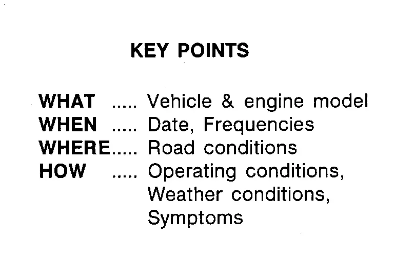
In general, customers have their own criteria for a problem. Therefore, it is important to understand the symptom and status well enough by asking the customer about the concerns carefully. In order to systemize all the information for the diagnosis, prepare the question sheet referring to the question points.

WORKSHEET SAMPLE

Question Sheet
Customer name MR/MS Engine # Manuf. Date
Incident Date VIN
Model & Year In Service Date
Trans. Mileage km/Mile
Symptoms □ Nissan Pathfinder Vehicle does not move (□ Any position □ Particular position )
□ No upshift (□ 1GR ⇒ 2GR □ 2GR ⇒ 3GR □ 3GR ⇒ 4GR □ 4GR ⇒ 5GR □ 5GR ⇒ 6GR □ 6GR ⇒ 7GR □ 7GR ⇒ 8GR □ 8GR ⇒ 9GR)
□ No downshift (□ 9GR ⇒ 8GR □ 8GR ⇒ 7GR □ 7GR ⇒ 6GR □ 6GR ⇒ 5GR □ 5GR ⇒ 4GR □ 4GR ⇒ 3GR □ 3GR ⇒ 2GR □ 2GR ⇒ 1GR)
□ Lock-up malfunction
□ Shift point too high or too low
□ Shift shock or slip
□ Noise or vibration
□ No kick down
□ No pattern select
□ Others
Frequency □ All the time □ Under certain conditions □ Sometimes ( times a day)
Weather conditions □ Not affected
Weather □ Fine □ Clouding □ Raining □ Snowing □ Other ( )
Temp. □ Hot □ Warm □ Cool □ Cold □ Temp. Approx. °C/°F
Humidity □ High □ Middle □ Low
Transmission conditions □ Not affected
□ Cold □ During warm-up □ After warm-up
□ Engine speed ( rpm)
Road conditions □ Not affected
□ In town □ In suburbs □ Freeway □ Off road (Up/Down)
Driving conditions □ Not affected
□ At starting □ While idling □ While engine racing □ At racing □ While cruising
□ While accelerating □ While decelerating □ While turning (Right/Left)
□ Nissan Pathfinder Vehicle speed [ km/h ( MPH)]
Other conditions

Additional Service When Replacing Tcm Nissan Pathfinder 2022

Description

When replacing the TCM, perform the following work. For work procedure, refer to Work Procedure.

WORK AFTER TCM REPLACEMENT

  • TCM programming

  • MAC key writing

  • Dog clutch position sensor calibration

  • Learning of solenoid characteristic

  • A/T clutch touch point learning

  • Clear DTC and test drive

Work Procedure

  • ASIST on the CONSULT has been synchronized to the current date.

  • All CONSULT software updates (if any) have been installed.

REPLACE TCM

Replace TCM. Refer to Removal and Installation.

>>

GO TO 2.

PERFORM TCM PROGRAMMING

With CONSULT

Perform TCM programming, according to “Programming” of CONSULT Operation Manual. Refer to CONSULT Operation Manual.

>>

GO TO 3.

WRITE MAC KEY

Perform MAC key writing, Refer to Description.

>>

GO TO 4.

PERFORM DOG CLUTCH POSITION SENSOR CALIBRATION

Perform dog clutch position sensor calibration. Refer to Description.

>>

GO TO 5.

PERFORM LEARNING OF SOLENOID CHARACTERISTIC

Perform learning of solenoid characteristic. Refer to Description.

>>

GO TO 6.

PERFORM A/T CLUTCH TOUCH POINT LEARNING

Perform A/T clutch touch point learning. Refer to Description.

>>

GO TO 7.

CLEAR DTC AND TEST DRIVE

  1. Ignition switch OFF and wait for 15 seconds.

  2. Ignition switch ON.

  3. Clear any DTCs that may have set and then test drive the Nissan Pathfinder vehicle.

>>

WORK END

Additional Service When Replacing Transaxle Assembly Nissan Pathfinder Fifth generation

Description

When replacing the transaxle assembly, perform the following work. For work procedure, refer to Work Procedure.

WORK AFTER A/T ASSEMBLY REPLACEMENT

  • TCM programming

  • MAC key writing

  • A/T clutch touch point learning

  • Clear DTC and test drive

Work Procedure

  • ASIST on the CONSULT has been synchronized to the current date.

  • All CONSULT software updates (if any) have been installed.

REPLACE A/T ASSEMBLY

Replace A/T assembly. Refer to Removal and Installation.

>>

GO TO 2.

PERFORM TCM PROGRAMMING

With CONSULT

Perform TCM programming, according to “Programming” of CONSULT Operation Manual. Refer to CONSULT Operation Manual.

>>

GO TO 3.

WRITE MAC KEY

Perform MAC key writing, Refer to Description.

>>

GO TO 4.

PERFORM A/T CLUTCH TOUCH POINT LEARNING

Perform A/T clutch learning. Refer to Description.

>>

GO TO 5.

CLEAR DTC AND TEST DRIVE

  1. Ignition switch OFF and wait for 15 seconds.

  2. Ignition switch ON.

  3. Clear any DTCs that may have set and then test drive the Nissan Pathfinder vehicle.

>>

WORK END

Additional Service When Replacing Control Valve Nissan Pathfinder SUV

Description

When replacing the control valve, perform the following work. For work procedure, refer to Work Procedure.

WORK AFTER CONTROL VALVE REPLACEMENT

  • Dog clutch position sensor calibration

  • Learning of solenoid characteristic

  • A/T clutch touch point learning

  • Clear DTC and test drive

Work Procedure

  • ASIST on the CONSULT has been synchronized to the current date.

  • All CONSULT software updates (if any) have been installed.

REPLACE CONTROL VALVE

Replace control valve. Refer to Removal and Installation.

>>

GO TO 2.

PERFORM DOG CLUTCH POSITION SENSOR CALIBRATION

Perform dog clutch position sensor calibration. Refer to Description.

>>

GO TO 3.

PERFORM LEARNING OF SOLENOID CHARACTERISTIC

Perform learning of solenoid characteristic. Refer to Description.

>>

GO TO 4.

PERFORM A/T CLUTCH TOUCH POINT LEARNING

Perform A/T clutch touch point learning. Refer to Description.

>>

GO TO 5.

CLEAR DTC AND TEST DRIVE

  1. Ignition switch OFF and wait for 15 seconds.

  2. Ignition switch ON.

  3. Clear any DTCs that may have set and then test drive the Nissan Pathfinder vehicle.

>>

WORK END

Dog Clutch Position Sensor Calibration Nissan Pathfinder 5th Gen

Description

When replacing the following parts, perform the dog clutch position sensor calibration. For work procedure, refer to Work Procedure.

  • TCM

  • Control valve

  • Sensor unit

  • Dog clutch A position sensor

Work Procedure

DOG CLUTCH POSITION SENSOR CALIBRATION

With CONSULT

  1. Ignition switch ON.

  2. Select “Work Support” in “TRANSMISSION”.

  3. Select "DOG CLUTCH POSITION SENSOR CALIBRATION".

  4. Maintain the following conditions.

    • A/T fluid temperature: 10 °C or more

    • Shift position: P

    • Engine speed: Idle speed

    • Release accelerator pedal

    • Depress brake pedal

    • Apply parking brake

    • Air conditioner: OFF

  5. Touch "Start".

  6. Shift to the D position within 10 seconds after the touch "Start".

  7. After work support is completed;

    • Shift to the P position

    • Ignition switch OFF and wait for 15 seconds.

>>

WORK END

Learning of Solenoid Characteristic Nissan Pathfinder 5th Gen

Description

When replacing the following parts, perform the learning of solenoid characteristic. For work procedure, refer to Work Procedure.

  • TCM

  • Control valve

  • Sensor unit

  • Dog clutch A position sensor

Work Procedure

LEARNING OF SOLENOID CHARACTERISTIC

With CONSULT

  1. Ignition switch ON.

  2. Select “Work Support” in “TRANSMISSION”.

  3. Select "LEARNING OF SOLENOID CHARACTERISTIC".

  4. Maintain the following conditions.

    • A/T fluid temperature: 30 °C - 110 °C

    • Shift position: P

    • Engine speed: Idle speed

    • Release accelerator pedal

    • Depress brake pedal

    • Apply parking brake

    • A/C: OFF

  5. Touch "Start".

  6. Shift to the D position within 10 seconds after the touch "Start".

  7. After work support is completed;

  • Shift to the P position

  • Ignition switch OFF and wait for 15 seconds.

>>

WORK END

A/t Clutch Touch Point Learning Nissan Pathfinder Fifth generation

Description

When replacing the following parts, perform the A/T clutch touch point learning. For work procedure, refer toWork Procedure .

  • TCM

  • Control valve

  • Sensor unit

  • Dog clutch A position sensor

Work Procedure

A/T CLUTCH TOUCH POINT LEARNING

With CONSULT

  1. Ignition switch ON.

  2. Select “Work Support” in “TRANSMISSION”.

  3. Select "A/T CLUTCH TOUCH POINT LEARNING".

  4. Maintain the following conditions.

    • A/T fluid temperature: 60 - 110 °C

    • Engine speed: Idle speed

    • A/C: OFF

    • Release accelerator pedal

    • Apply parking brake

    • Shift to the D posiiton while depressing the brake pedal

  5. Touch "Start".

  6. After work support is completed;

>>

GO TO 2.

IDLE AIR VOLUME LEARNING

Perform idle air volume learning. Refer to Description.

>>

WORK END

Mac Key Writing Nissan Pathfinder Fifth generation

Description

When replacing TCM, it is necessary to write MAC key to TCM. Write MAC key to TCM according to "MAC Key writing" procedure of "CONSULT Operation Manual". Refer to Work Procedure.

  • Ignition switch ON

  • CONSULT is connected to internet

Work Procedure

PERFORM MAC KEY WRITING

  1. Ignition switch ON.

  2. Select "MAC Key writing" on "Work Support" of "TRANSMISSION" using CONSULT.

  3. Touch "Write".

YES>>

WORK END

A/t Fluid Cooler System Nissan Pathfinder

Exploded View
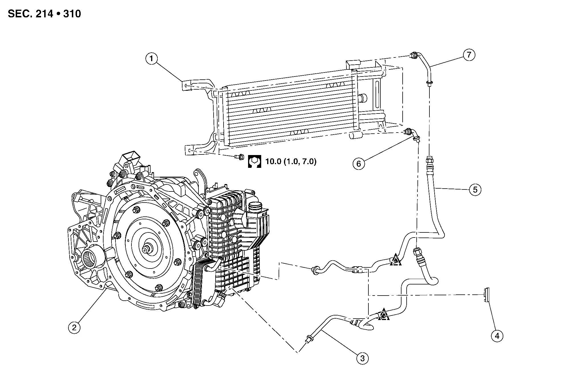
1. A/T fluid cooler 2. Transaxle assembly 3. A/T fluid cooler hose A
4. Hose clamp 5. A/T fluid cooler hose B 6. A/T fluid cooler tube A
7. A/T fluid cooler tube B Clip

Cleaning

A/T Fluid Cooler Flush

Always perform a A/T Fluid Cooler Flush after any one of the following:

  • A/T (transaxle) assembly overhaul, internal repair or replacement

  • Control valve replacement

  • Torque converter replacement

A/T FLUID COOLER CLEANING PROCEDURE — WITH TOW PACKAGE

Remove front under cover. Refer to Removal and Installation.

Position an oil drain pan under the A/T fluid cooler.

Position an oil drain pan under the A/T fluid warmer.

Disconnect the A/T fluid cooler hose A and A/T fluid cooler hose B from the A/T fluid warmer. Refer to Exploded View.

Allow any transmission fluid that remains in the A/T fluid cooler hoses to drain into the oil drain pan.

Flush A/T fluid cooler (radiator) and hoses using the following steps:Attach a suitable hose (A) to the A/T fluid cooler hose (1).
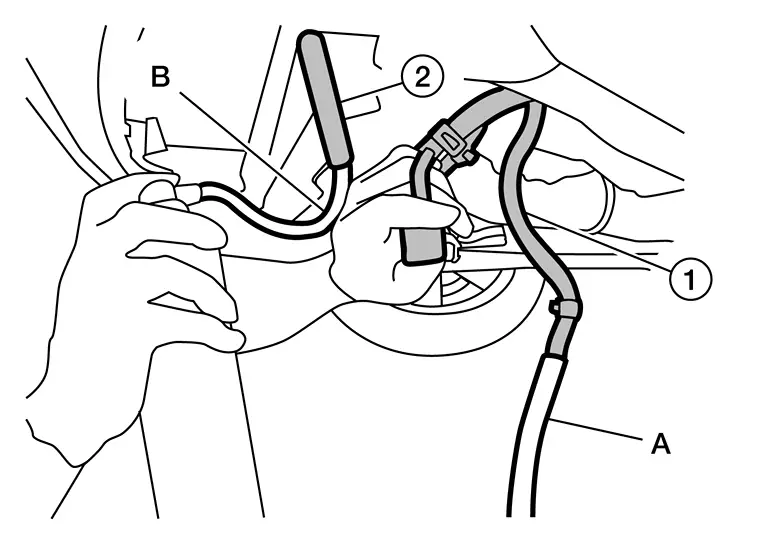
Hose inside diameter : 16 mm (5/8 in)

Insert extension adapter hose (B) from a can of Transmission Cooler Cleaner, into A/T fluid cooler hose (2). Holding the can and hose as high as possible, spray Transmission Cooler Cleaner in a continuous stream into the A/T fluid cooler (radiator) inlet side hose until it flows from the outlet side hose for five seconds.

Attach a suitable hose over the end of the A/T fluid cooler hose (2) that was used as the flush inlet.
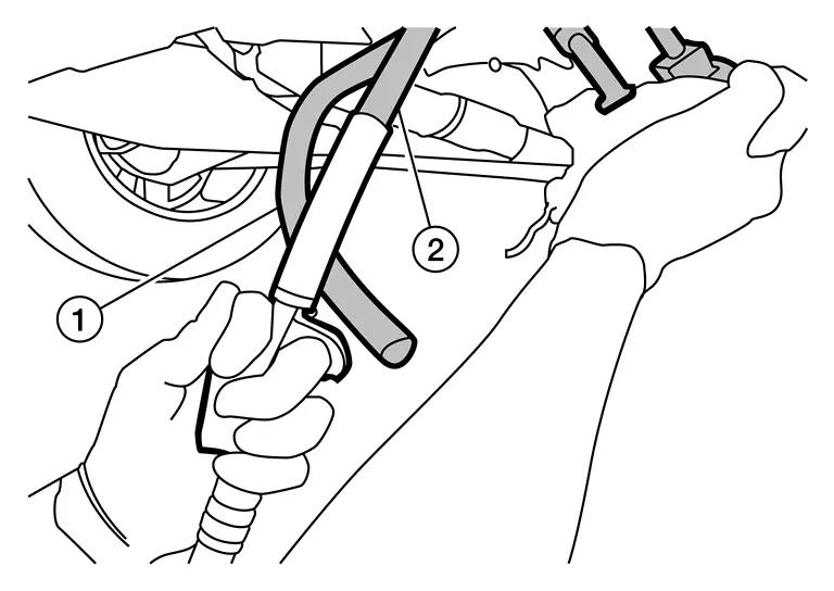
Hose inside diameter : 16 mm (5/8 in)

Blow compressed air through A/T fluid cooler hose (2) for 10 seconds to force remaining fluid out of A/T fluid cooler hose (1).

Air pressure : 490-883 kPa (5-9 kg/cm2, 70-128 psi)

Repeat steps 6-8 one additional time, then proceed to step 10.

Reverse flush the A/T fluid cooler. Install Transmission Cooler Cleaner to A/T fluid cooler hose (1), then reverse flush A/T fluid cooler by repeating steps 6-8 twice.

Remove A/T fluid cooler. Refer to Removal and Installation.

Install suitable hoses onto the inlet side and outlet side of the A/T fluid cooler.

Hose inside diameter: 16 mm (5/8 in)
Inlet side hose (A) : 102 mm (4 in)
Outlet side hose (B) : 152 mm (6 in)

Insert the extension adapter hose from a can of Transmission Cooler Cleaner through inlet side of A/T fluid cooler letting cleaner drain through outlet side.

Remove suitable hoses from inlet side and outlet side of A/T fluid cooler.

Insert the tip of air gun into the end of the A/T fluid cooler inlet side (A).

Remove any remaining fluid using compressed air at the inlet side of A/T fluid cooler for 10 seconds.

Air pressure : 490-883 kPa (5-9 kg/cm2, 70-128 psi)

Install suitable hoses onto the inlet side and outlet side of the A/T fluid cooler.

Hose inside diameter: 16 mm (5/8 in)
Inlet side hose (A) : 102 mm (4 in)
Outlet side hose (B) : 152 mm (6 in)

While holding the hoses securely to the fluid cooler, flush two full quarts of NISSAN Matic R ATF (or equivalent) with a 1-pint suction gun.

Remove suitable hoses from inlet side and outlet side of A/T fluid cooler.

Insert the tip of air gun into A/T fluid cooler inlet side.

Remove any remaining NISSAN Matic R ATF (or equivalent) using compressed air at the inlet side of A/T fluid cooler for 10 seconds.

Air pressure : 490-883 kPa (5-9 kg/cm2, 70-128 psi)

Install A/T fluid cooler hose A and A/T fluid cooler hose B, to A/T fluid warmer. Refer to Exploded View.

Fill the transaxle assembly with A/T fluid. Refer to Replacement.

A/T FLUID COOLER CLEANING PROCEDURE — WITHOUT TOW PACKAGE

Remove front under cover. Refer to Removal and Installation.

Position an oil drain pan under the radiator.

Position an oil drain pan under the A/T fluid warmer.

Disconnect the A/T fluid cooler hose A and A/T fluid cooler hose B from the A/T fluid warmer. Refer to Exploded View.

Allow any transmission fluid that remains in the A/T fluid cooler hoses to drain into the oil drain pan.

Flush A/T fluid cooler and hoses using the following steps:Attach a suitable hose (A) to the A/T fluid cooler hose (1).
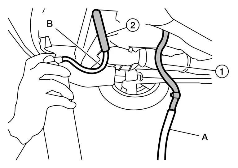
Hose inside diameter : 16mm (5/8 in)

Insert extension adapter hose (B) from a can of Transmission Cooler Cleaner, into A/T fluid cooler hose (2). Holding the can and hose as high as possible, spray Transmission Cooler Cleaner in a continuous stream into the radiator inlet side hose until it flows from the outlet side hose for five seconds.

Attach a suitable hose over the end of the A/T fluid cooler hose (2) that was used as the flush inlet.
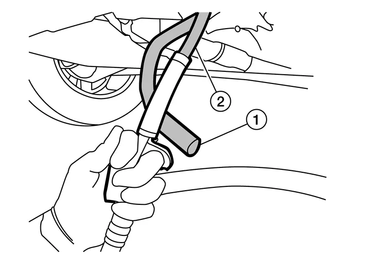
Hose inside diameter : 16mm (5/8 in)

Blow compressed air through A/T fluid cooler hose (2) for 10 seconds to force remaining fluid out of A/T fluid cooler hose (1).

Air pressure : 490-883 kPa (5-9 kg/cm2, 70-128 psi)

Repeat steps 6-8 one additional time, then proceed to step 10.

Reverse flush the A/T fluid cooler. Install Transmission Cooler Cleaner to A/T fluid cooler hose (1), then repeat steps 6-8 twice.

Install A/T fluid cooler hose A and A/T fluid cooler hose B to the A/T fluid warmer. Refer to Exploded View.

Fill the transaxle assembly with A/T fluid. Refer to Replacement.

Inspection

After performing all procedures, ensure that all remaining oil is cleaned from all components.

A/t Position Nissan Pathfinder Fifth generation

Inspection

CHECK SELECTOR LEVER OPERATION

  1. Shift the selector lever and check for excessive effort, sticking, noise or rattle.

  2. The selector lever automatically moves back to the H (home) position after it is operated.
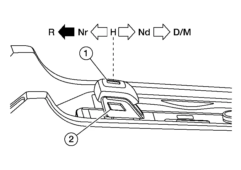
    : P position switch

    : Press the button to shift

    : Shift without pressing the button

  3. The selector lever cannot move to R position unless press the knob button.

Is the inspection result normal?

YES>>

GO TO 2.

NO>>

Repair or replace the electric shift selector. Refer to Removal and Installation.

CHECK SHIFT POSITION

Check the following during engine running.

  1. When the selector lever shifts to each position during depressing the brake pedal, the shift position normally changes.

  2. When the brake pedal is not depressed at the P position, the shift position does not change even if the selector lever is operated.

  3. When the P position switch is pressed and released at any shift position except the P position, the shift position changes into the P position.

  4. When the selector lever shifts to the D position again at the D position, the shift position changes into the M mode.

  5. When the selector lever shifts to the D position again at the M mode, the shift position changes into the D position.

  6. When the ignition switch turns off, the shift position automatically changes into the P position. (The selector indicator lamp of the P position turns ON.)

Is the inspection result normal?

YES>>

INSPECTION END

NO>>

Check the electric shift system.

How to Erase Permanent Dtc Nissan Pathfinder 2022

Description

WHEN A DTC IS STORED IN TCM

When a DTC is stored in TCM and MIL is ON, a permanent DTC is erased with MIL shutoff if the same malfunction is not detected after performing the driving pattern for MIL shutoff three times in a raw.

In case of DTC of one trip detection diagnosis, when NG is detected at one trip, MIL turns ON and permanent DTC is displayed.
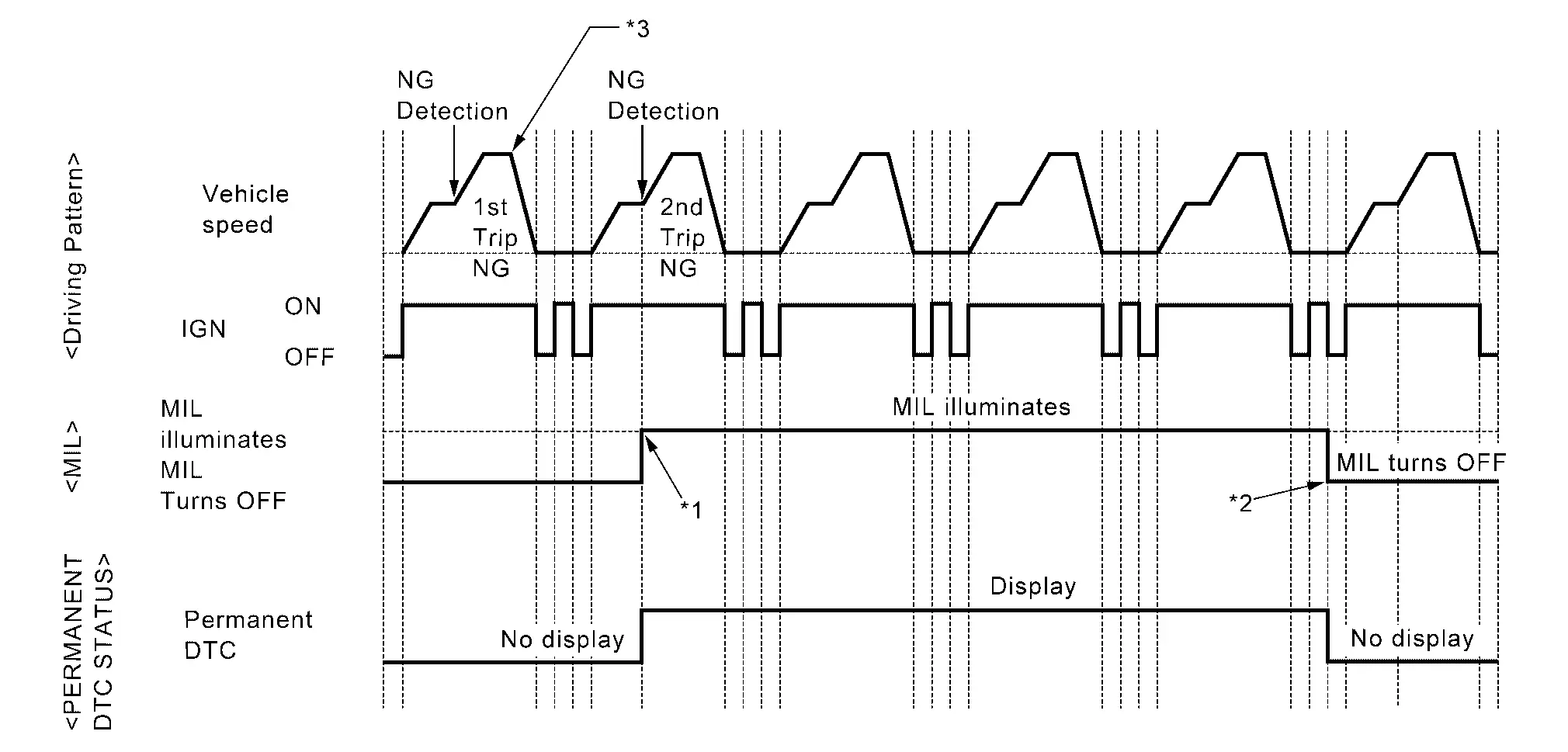
*1: When the same malfunction is detected in two consecutive trips, MIL will illuminate. *2: MIL will turn off after Nissan Pathfinder vehicle is driven 3 times (driving pattern B) without any malfunctions. *3:

Diagnosis condition *A and diagnosis delay time *A for each DTC are satisfied.

(*A: For details of these, refer to DTC/CIRCUIT DIAGNOSIS >> DTC (Pxxxx or Uxxx) >> DTC Description >> DTC DETECTION LOGIC.)

WHEN A DTC IS NOT STORED IN TCM

The erasing method depends on a permanent DTC stored in TCM.

For erase procedure of permanent DTC, refer to Work Procedure.

PERMANENT DTC ITEM

For permanent DTC items, MIL turns ON. Refer to DTC Index.

Work Procedure

CHECK DTC

Check DTC.

Is any DTC detected?

YES>>

Repair malfunction(s) and erase DTC.

NO>>

GO TO 2.

CHECK PERMANENT DTC

With CONSULT

  1. Ignition switch OFF and wait at least 60 seconds.

  2. Ignition switch ON.

  3. Ignition switch OFF and wait at least 60 seconds.

  4. Ignition switch ON.

  5. Select “PERMANENT DTC STATUS” mode with CONSULT.

With GST

  1. Ignition switch OFF and wait at least 60 seconds.

  2. Ignition switch ON.

  3. Ignition switch OFF and wait at least 60 seconds.

  4. Ignition switch ON.

  5. Select Service $0A with GST.

Is any permanent DTC detected?

YES>>

GO TO 3.

NO>>

END

HOW TO ERASE PERMANENT DTC

  1. Perform "DTC CONFIRMATION PROCEDURE "of detected permanent DTC.

  2. Drive the Nissan Pathfinder vehicle following to driving pattern.

    • The state of driving at 40 km/h reaches 300 seconds or more in total.

    • Idle speed lasts 30 seconds or more.

    • A lapse of 600 seconds or more after engine start.

>>

GO TO 4.

CHECK PERMANENT DTC

With CONSULT

  1. Ignition switch OFF and wait at least 60 seconds.

  2. Ignition switch ON.

  3. Ignition switch OFF and wait at least 60 seconds.

  4. Ignition switch ON.

  5. Select “PERMANENT DTC STATUS” mode with CONSULT.

With GST

  1. Ignition switch OFF and wait at least 60 seconds.

  2. Ignition switch ON.

  3. Ignition switch OFF and wait at least 60 seconds.

  4. Ignition switch ON.

  5. Select Service $0A with GST.

Is any permanent DTC detected?

YES>>

GO TO 1.

NO>>

END