Removal and Installation - Rear Brake Caliper Assembly ++
Exploded View

| 1. | Bleeder cap | 2. | Bleeder valve | 3. | Brake caliper assembly |
| 4. | Lower slide pin | 5. | Slide pin boot | 6. | Torque member |
| 7. | Bushing | 8. | Upper slide pin | A. | Slide pin bolt |
| B. | Parking brake actuator | C. | Torque member bolt | D. | Rubber grease |
Removal and Installation
REMOVAL
Observe the brake fluid level in the reservoir tank. Partially drain brake fluid if necessary. Refer to Draining.
Remove the rear wheel and tire using a power tool. Refer to Removal and Installation.
Secure the disc brake rotor using wheel nuts.
Disconnect the harness connector from the rear brake caliper.
Remove the union bolt, the copper sealing washers, and separate the brake hose from the brake caliper. Discard the copper sealing washers. Refer to Exploded View.
Remove the slide pin bolts. Refer to Exploded View.
Remove the brake caliper from the torque member.
Remove the slide pins from the torque member.
Remove the brake pads, shims, shim cover, wear indicators, and pad retainers from the torque member. Refer to Exploded View.
Remove the bolts and the torque member.
INSTALLATION
Install the torque member and the bolts. Tighten the bolts to the specified torque. Refer to Exploded View.
Apply rubber grease to the slide pins.
Install the slide pins to the torque member.
Install the brake pads, shims, shim cover, wear indicators, and pad retainers to the torque member. Refer to Exploded View.
Install the brake caliper to the torque member.
Install the slide pin bolts. Tighten the slide pin bolts to the specified torque.
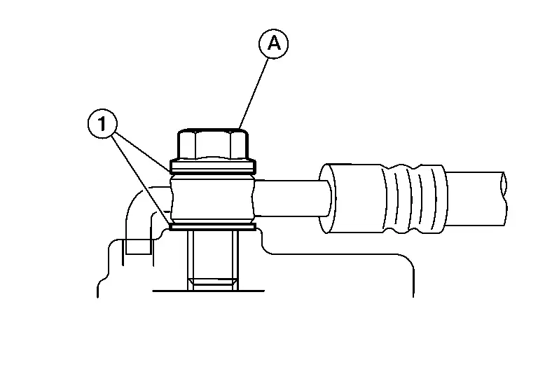
Assemble the union bolt (A) and the copper sealing washers (1) to the brake hose and install it as an assembly to the brake caliper. Align the brake hose L-pin by aligning it with the brake caliper hole, and tighten the union bolt to the specified torque. Refer to Exploded View.
Connect the harness connector to the rear brake caliper.
Refill with new brake fluid and bleed air from the brake system. Refer to Bleeding Brake System.
Depress the brake pedal several times and verify that drag does not exist.
Install the rear wheel and tire. Refer to Removal and Installation.
INSPECTION AFTER INSTALLATION
Check the drag of the rear disc brake. If any drag is found, perform the following procedure:Remove the rear brake pads. Refer to Removal and Installation.
Install the brake pads.
Depress the brake pedal several times. Check the drag of the rear disc brake again. If any drag is found, disassemble the brake caliper body. Refer to Disassembly and Assembly.
Burnish contact surfaces after replacing the brake caliper or if a soft pedal occurs at very low mileage. Refer to Periodic Maintenance Operation.
Disassembly and Assembly
DISASSEMBLY
Remove the brake caliper from the vehicle. Refer to Removal and Installation.
Remove the slide pin boots from the torque member. Refer to Exploded View.
Remove the bushing from the slide pin.
Remove the bleeder valve and cap.
Perform the inspection after disassembly.
INSPECTION AFTER DISASSEMBLY
Brake Caliper Body
Check the brake caliper body for rust, wear, cracks, and damage. Replace the brake caliper if any abnormal condition is detected.
Torque Member
Check the torque member for rust, wear, cracks, and damage. Replace the brake caliper if any abnormal condition is detected.
Slide Pins and Bolts
Check the slide pins and bolts for rust, wear, cracks, and damage. Replace the parts if any abnormal condition is detected.
ASSEMBLY
Install the bleeder valve and cap. Refer to Exploded View.
Apply rubber grease to the matching surfaces (A) of the slide pin (1) and the bushing (2).
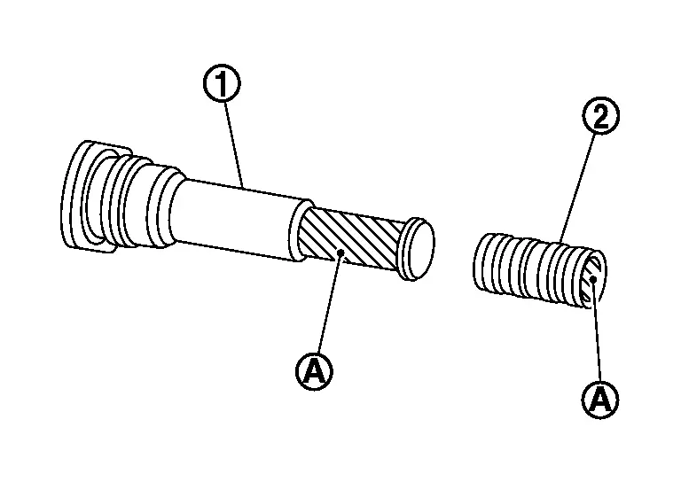
Install the bushing to the slide pin.
Apply rubber grease to the matching surfaces (A) of the slide pins (1) and the slide pin boots (2).
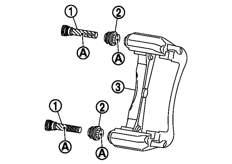
Install the slide pins and slide pin boots to the torque member (3).
Install the brake caliper to the Nissan Pathfinder vehicle. Refer to Removal and Installation.