Steering System - Removal and Installation
- Steering Wheel
- Steering Column
- Lower Joint
- Steering Gear and Linkage
- Heated Steering Wheel Switch
Steering Wheel Nissan Pathfinder Fifth generation
Exploded View
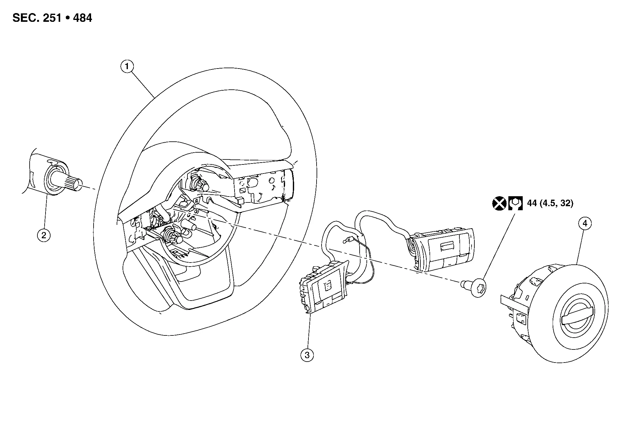
| 1. | Steering wheel | 2. | Steering column | 3. | ICC Steering switches |
| 4. | Driver air bag module |
Removal and Installation
REMOVAL
Set the front wheels and tires to the straight-ahead position.
Remove driver air bag module. Refer to Removal and Installation.
Remove steering wheel bolt.
Disconnect harness connector from ICC steering switches.
Remove steering wheel using suitable tool.
Inspect steering wheel near the puller holes for damage. Replace as necessary.
Remove ICC steering switches (if necessary).
INSTALLATION
Installation is in the reverse order of removal.
Align spiral cable correctly before installing steering wheel. Make sure that the spiral cable is in the neutral position. Refer to Removal and Installation.
Steering Column Nissan Pathfinder R53
Exploded View
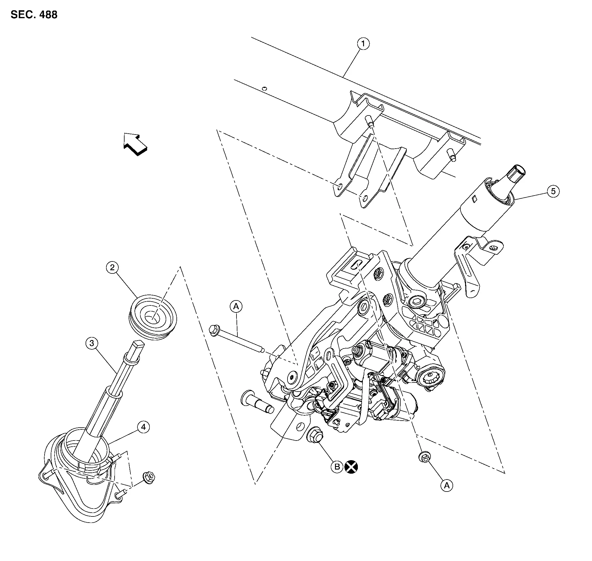
| 1. | Steering member | 2. | Hole cover seal | 3. | Lower joint |
| 4. | Hole cover | 5. | Steering column | A. | Refer to Installation. |
| B. | Refer to Installation. |  |
Front |
Removal and Installation
REMOVAL
Set the front wheels and tires to the straight-ahead position.
Remove combination switch. Refer to Removal and Installation.
Remove instrument lower panel LH. Refer to Removal and Installation.
Disconnect tilt and telescopic harness connectors (if equipped).
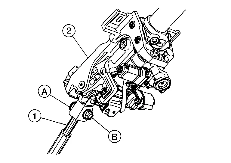
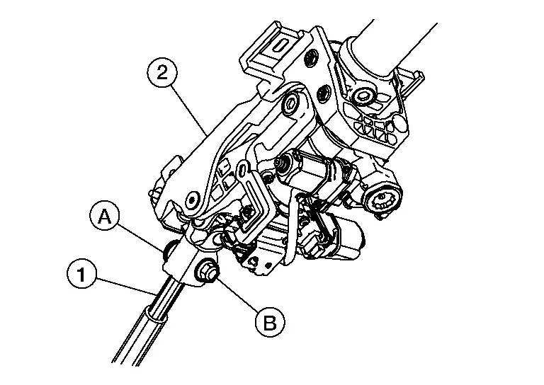
Remove lock nut (B) and pinch bolt (A). Separate lower joint (1) from steering column (2).
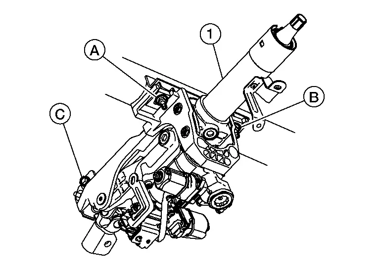
Remove nut (A), nut (B), bolt (C), and steering column (1).
INSTALLATION
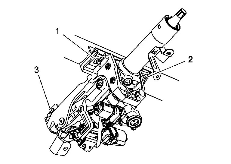
Install steering column to steering member with nuts and bolt finger tight in the sequence shown.
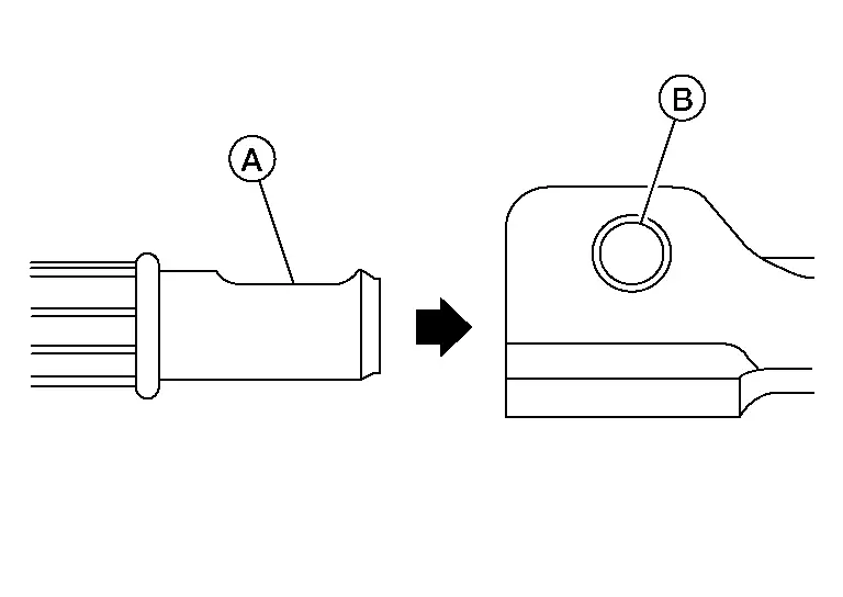
Install lower joint to steering column. Align lower joint shaft groove (A) with steering column yoke bolt hole (B).
Tighten steering column nuts and bolt to specification in the sequence shown.

| Nut 1 | : 16 N·m |
| Nut 2 | : 16 N·m |
| Bolt 3 | : 23 N·m |
Install pinch bolt (A) and lock nut (B) finger tight. Verify pinch bolt is properly seated in lower joint shaft (1) groove.
Tighten pinch bolt lock nut to specification.
| Lock nut | : 44 N·m |
Installation of remaining components is in the reverse order of removal.
Lower Joint Nissan Pathfinder SUV
Exploded View

| 1. | Lower joint | 2. | Steering gear | 3. | Steering column |
 |
Front |
Removal and Installation
REMOVAL
Set the front wheels and tires to the straight-ahead position.
Remove instrument lower panel LH. Refer to Removal and Installation.
Remove lock nut (B) and pinch bolt (A). Separate lower joint (1) from steering column (2).
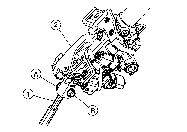
Remove pinch bolt (A). Separate lower joint (1) from steering gear (2).

 |
: Front |
Remove lower joint from engine compartment.
INSTALLATION
Install lower joint to steering gear. Align steering gear pinion shaft groove (A) with lower joint yoke bolt hole (B).
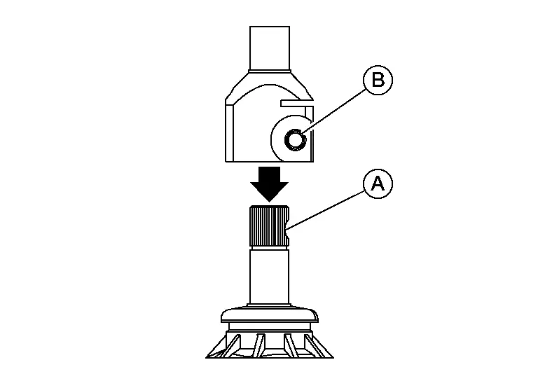
Install lower joint (1) pinch bolt (A) finger tight. Verify pinch bolt is properly seated in steering gear (2) pinion shaft groove.
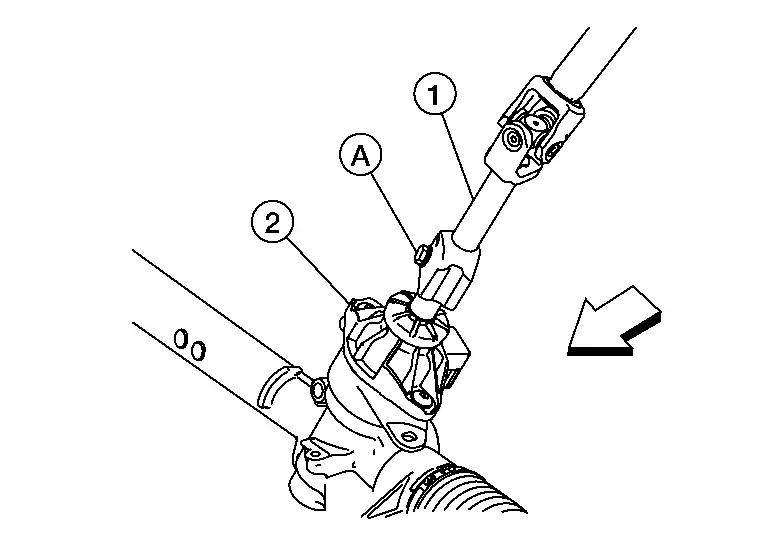
 |
: Front |
Install lower joint to steering column. Align lower joint shaft groove (A) with steering column yoke bolt hole (B).
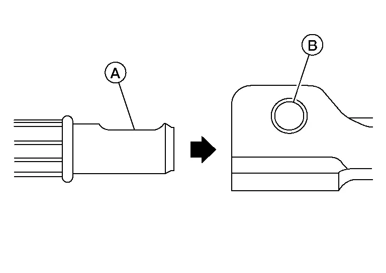
Install pinch bolt (A). Verify pinch bolt is properly seated in lower joint shaft (1) groove. Install lock nut (B) finger tight.
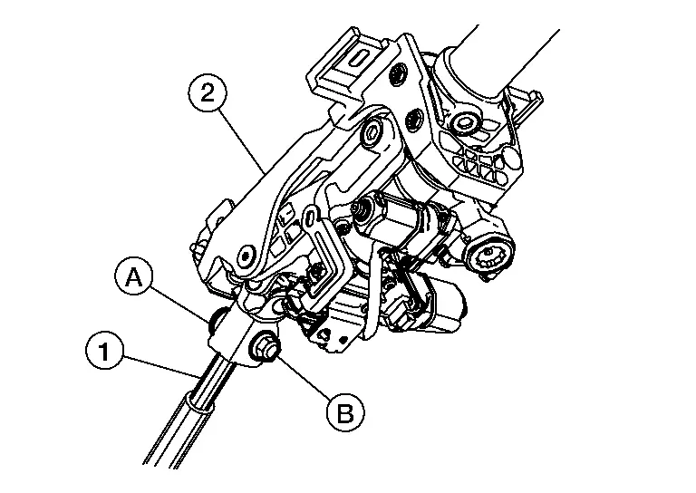
Tighten lock nut (at steering column) to specification.
| Lock nut | : 44 N·m |
Tighten pinch bolt (at steering gear) to specification.
| Pinch bolt | : 26 N·m |
Installation of remaining components is in the reverse order of removal.
Steering Gear and Linkage Nissan Pathfinder
Exploded View
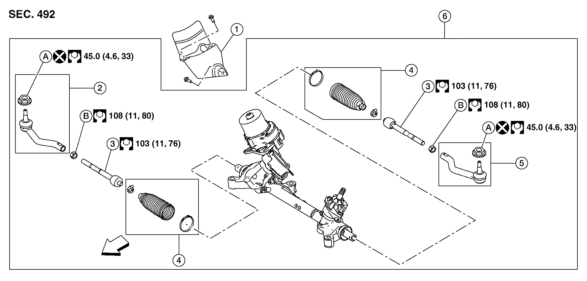
| 1. | Heat shield | 2. | Outer socket (RH) | 3. | Inner socket |
| 4. | Boot | 5. | Outer socket (LH) | 6. | Steering gear and linkage assembly |
| A. | Outer socket nut | B. | Inner socket lock nut |  |
Front |
Removal and Installation - Outer socket
REMOVAL
Remove front wheel and tire using power tool.
Loosen inner socket lock nut (A).
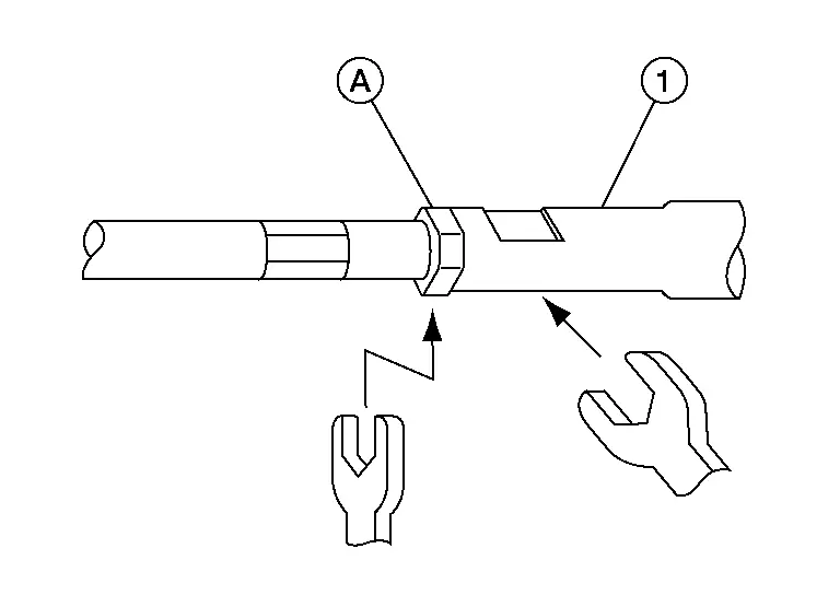
Loosen outer socket nut and separate outer socket from steering knuckle using suitable tool.
Remove outer socket nut and outer socket.
INSTALLATION
Install outer socket to inner socket.
Adjust inner socket to standard length (L), and then tighten inner socket lock nut to the specified torque. Refer to Exploded View. Check length of inner socket (L) again after tightening inner socket lock nut. Make sure that the length is the standard.
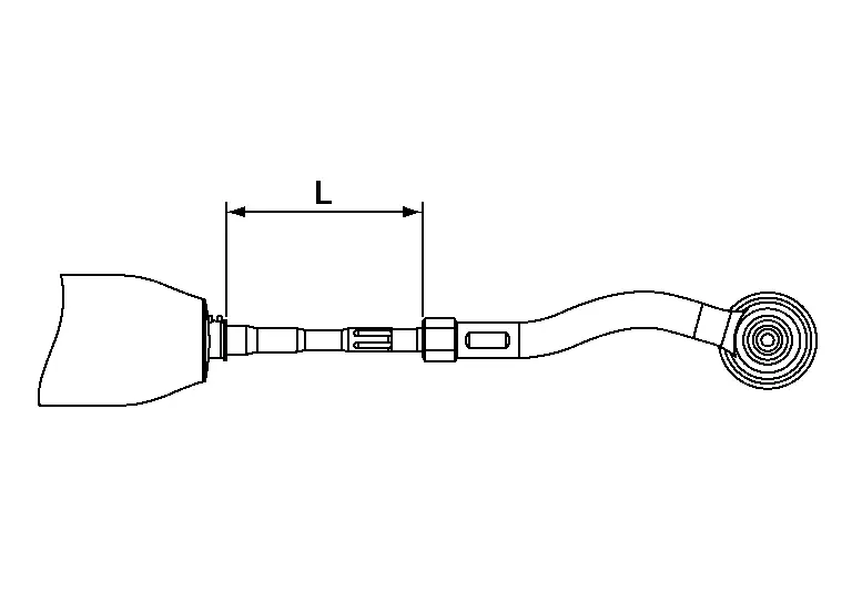
| Inner socket length (L) | : Refer to Power Steering Gear. |
Install outer socket to steering knuckle.
Install outer socket nut to outer socket. Refer to Exploded View.
Install front wheel and tire. Refer to Removal and Installation.
Removal and Installation - Boot
REMOVAL
Remove outer socket. Refer to Removal and Installation - Outer socket.
Remove inner socket lock nut.
Remove the nuts and separate the stabilizer connecting rods from the stabilizer bar. Reposition the stabilizer bar. Refer to Removal and Installation.
Remove small boot clamp and large boot clamp.
Remove boot.
INSTALLATION
Install large end of boot (1) to steering gear housing.
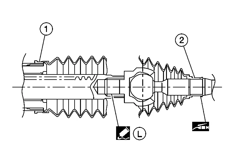
Apply silicone grease between the inner socket and small end of boot (2). Install small end of boot to inner socket boot mounting groove.
Install small boot clamp (B).
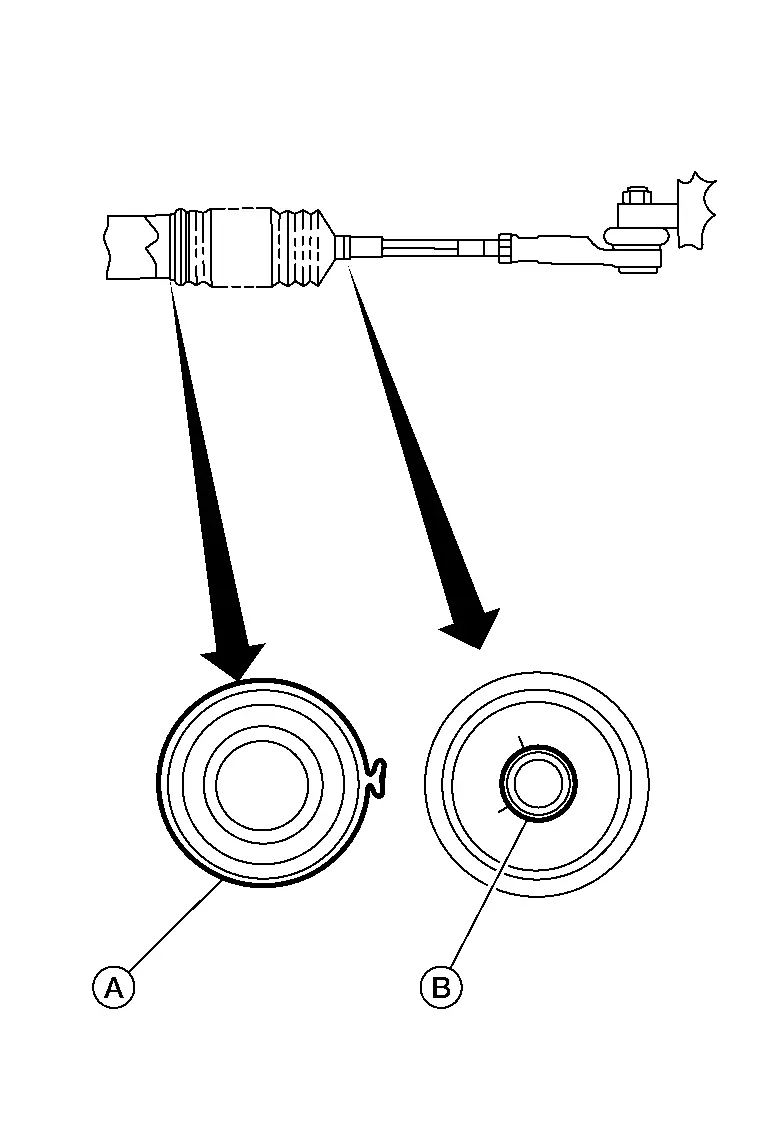
Install large boot clamp (A) using Tool.
| Tool number | : KV40107300 (NI-51751) |
Install the nuts and stabilizer connecting rods to the stabilizer bar. Refer to Removal and Installation.
Partially thread the inner socket lock nut on the inner socket.
Install the outer socket. Refer to Removal and Installation - Outer socket.
Removal and Installation - Inner socket
REMOVAL
Remove boot. Refer to Removal and Installation - Boot.
Remove inner socket.
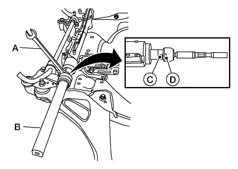
INSTALLATION
Apply medium strength thread locker to threads of inner socket. Tighten inner socket to the specified torque. Refer to Exploded View.
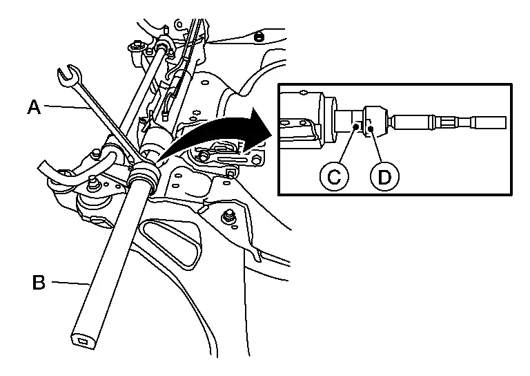
Install boot. Refer to Removal and Installation - Boot.
Heated Steering Wheel Switch Nissan Pathfinder
Removal and Installation
For removal and installation of the heated steering wheel switch, refer to Removal and Installation.