Charging flap unit
In this manual: Charging flap unit
3steps
~18min
2/5difficulty
Done 0 of 3
- Assembly overview - charging flap unit
- Removing and installing charging flap unit
- Removing and installing charging flap
Assembly overview - charging flap unit
- Charging flap unit
- Renew after removing
- ⇒ Rep. gr. 55 ; Removing and installing charging flap unit
- Charging flap
- ⇒ Rep. gr. 55 ; Removing and installing charging flap
- Charging socket cap
- Water drain hose
- Actuator for high-voltage charging flap lock 1 - F496-
- ⇒ Rep. gr. 57 ; Removing and installing actuator for high-voltage charging flap lock 1 [F496]
- Bolt
- Qty. 2
- 1,5 N·m
- Bolt
- Qty. 2
- 1,5 N·m
- LED module for charging socket 1 - L263-
- ⇒ Rep. gr. 55 ; Removing and installing LED module for charging socket 1 [L263]

Removing and installing charging flap unit
Special tools and workshop equipment required
- wedge set - VAS 895 015-
Removing
Important
- The charging flap unit cannot be removed free of damage.
- When renewing components, identification labels from old parts indicating the corresponding spare part numbers in the ⇒ Electronic parts catalogue (ETKA) must be attached to the respective new parts as required by registration regulations.
- Renew any illegible or damaged identification labels and information or warning signs found on components of this vehicle, and affix the new ones in the same location. For allocation, see ⇒ Electronic parts catalogue (ETKA) .
Note
Locking devices of charging flap unit -1- are located at height of swage lines -3- and -arrow A- to -arrow E-. The number and position of the locking devices depends on the model.
- Spray soapy solution onto edge of charging flap unit -1-.
- Guide wedge number 26 -2- from wedge set - VAS 895 015- between edge of charging flap unit -1- and side panel -4- and release locking devices. Guide wedge No. 8 from wedge set - VAS 895 015- into gap between edge of charging flap unit -1- and side panel -4-, and leave it inserted.
- Release locking devices in the sequence -arrow A- to -arrow E- using wedge number 26 from wedge set - VAS 895 015- .

NOTICE
Risk of damage caused in the process of swinging out the charging flap unit.
Risk of paint damage.
- Fold in charging flap.
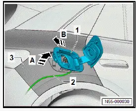
- Swing charging flap unit -1- in direction of -arrow A- out of side panel -3-. While doing so, fold in charging flap enough so that it does not come into contact with side panel -3-.
- Disconnect electrical connectors.
- Pull out charging flap unit -1- together with water drain hose -2- in direction of -arrow B-.
- Detach water drain hose -2- from charging flap unit -1-.
Installing
Install in reverse order of removal, observing the following:
- Insert water drain hose -2- in direction of -arrow A- through opening in charging flap unit -1- and then pull it through to stop.
- Insert water drain hose -2- in direction of -arrow B- into side panel -3-.
NOTICE
Risk of damage caused in the process of swinging in the charging flap unit.
Risk of paint damage.
- Fold in charging flap.

- Swing charging flap unit -1- in direction of -arrow C- into side panel -3-. Fold in charging flap enough so that it does not come into contact with side panel -3-.
- Connect electrical connectors.
- Push charging flap unit -1- in direction of -arrow D- against side panel until locking devices engage.
- Perform functional check with charging flap open.
Removing and installing charging flap
Special tools and workshop equipment required
- scraper set - VAS 6845-
- When renewing components, identification labels from old parts indicating the corresponding spare part numbers in the ⇒ Electronic parts catalogue (ETKA) must be attached to the respective new parts as required by registration regulations.
- Renew any illegible or damaged identification labels and information or warning signs found on components of this vehicle, and affix the new ones in the same location. For allocation, see ⇒ Electronic parts catalogue (ETKA) .
Removing
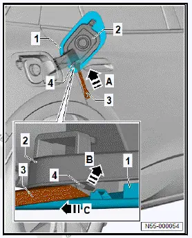
- Push wedge no. 3 -3- from scraper set - VAS 6845- in direction of -arrow A- between charging flap -1- and charging flap unit-2-.
- Unclip charging flap -1- in direction of -arrow B- from fastener -4-.
- Push charging flap -1- in direction of -arrow C-, and detach it.
Installing
Install in reverse order of removal, observing the following:
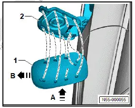
- Fit charging flap -1- in direction of -arrow A- onto charging flap unit -2-.
- Push charging flap -1- in direction of -arrow B- onto fasteners of charging flap unit -2-.
Removing and installing LED module for charging socket 1 [L263]
Removing
- Remove charging flap unit ⇒ Rep. gr. 55 ; Removing and installing charging flap unit .
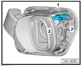
- Unscrew bolts -2-.
- Remove LED module for charging socket 1 - L263- -1-.
Installing
Install in reverse order of removal, observing the following:
Tightening torques
- ⇒ Rep. gr. 55 ; Assembly overview - charging flap unit
Was this page helpful?