Roof trims
In this manual: Roof trims
~4min read
- Assembly overview moulded headliner
- Removing and installing moulded headliner
- Installing roof reinforcement to body
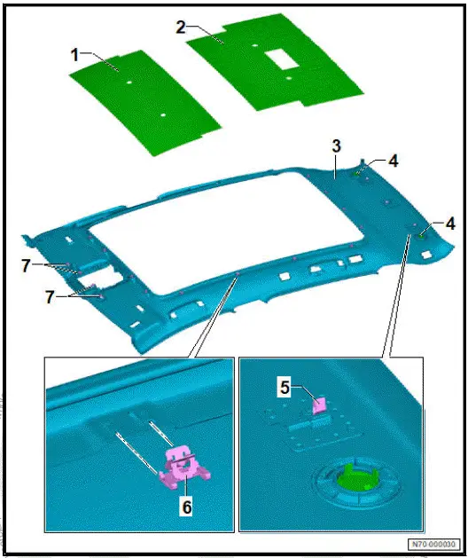
Assembly overview moulded headliner
- Roof reinforcement
- Depending on equipment version
- ⇒ Rep. gr. 70 ; Installing roof reinforcement to body
- Roof reinforcement
- Depending on equipment version
- ⇒ Rep. gr. 70 ; Installing roof reinforcement to body
- Moulded headliner
- Depending on equipment version
- ⇒ Rep. gr. 70 ; Removing and installing moulded headliner
- Plug
- qty. 2
- Clip
- qty. 3
- Clip
- Depending on equipment version
- qty. 16
- Clip
- qty. 4
Removing and installing moulded headliner
Special tools and workshop equipment required
- pliers - T10558A
Removing
- Release upper A-pillar trims ⇒ "6.9 Removing and installing upper A-pillar trim"
- Release upper B-pillar trims ⇒ "6.12 Removing and installing upper B-pillar trim"
- Remove bench seat ⇒ Rep. gr. 72 ; Removing and installing bench seat/individual seats .
- Remove rear sill panel moulding ⇒ "6.8 Removing and installing rear sill panel moulding"
- Remove C-pillar trims ⇒ Rep. gr. 70 ; Removing and installing C-pillar trim .
- Remove sun visors ⇒ Rep. gr. 68 ; Removing and installing sun visor .
- Remove sun visor centre mount ⇒ Rep. gr. 68 ; Removing and installing sun visor centre mount .
- Remove front interior light - WX1- ⇒ Electrical system; Rep.
gr. 96 ; Controls; Removing and installing front interior light [WX1] .
- Remove roof grab handles ⇒ Rep. gr. 68 ; Removing and installing roof grab handle .
Vehicles with glass panel
- Open sunroof roller blind.
All vehicles (continued)
- Release rear seat backrests, and fold them forwards.
- Move front seats to foremost and lowest position.
- When carrying out the steps below, always make sure that the pliers - T10558A- is positioned centrally in the retaining clips.
NOTICE
Risk of damage from incorrect handling.
- Do not kink moulded headliner.
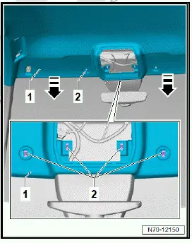
- Unclip retaining clips -2- from moulded headliner retaining frame -1- using pliers - T10558A- .
- Hold moulded headliner -1- pretensioned in direction of -arrow- in such a way that released retaining clips -2- do not engage again.
Important
- The aid of an additional person is required for the subsequent work steps.
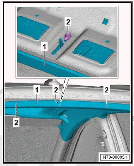
- While holding moulded headliner -1- in position, unclip retaining clips -2- in rear area.
Vehicles with glass panel
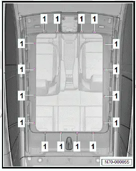
- Unclip retaining clips -1- all around.
All vehicles (continued)
- Disconnect electrical connector.
Important
- The aid of an additional person is required for the subsequent work steps.
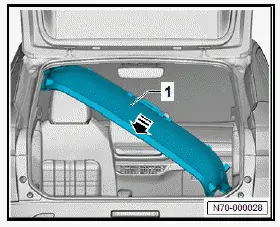
- Carefully remove moulded headliner -1- through rear lid opening in direction of -arrow-.
Installing
Install in reverse order of removal, observing the following:
- Make sure that electrical wire is not trapped.
Installing roof reinforcement to body
Special tools and workshop equipment required
- electric cutter - V.A.G 1561A-
- hand-cartridge gun - V.A.G 1628-
- scraper - V.A.G 1561/20-
Removing
- Remove moulded headliner ⇒ Rep. gr. 70 ; Removing and installing moulded headliner .
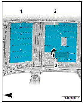
- Cut roof reinforcements -1- and -2- into approx. 6 cm wide strips -3-.
- Pull strips -3- in direction of -arrow- off roof.
- Remove adhesive residue using electric cutter - V.A.G 1561A- and scraper - V.A.G 1561/20- .
- If the paintwork structure is damaged when the roof reinforcements are removed, repair paintwork damage according to the ⇒ Paintwork structure specifications.
- On vehicles with 2 bitumen mats behind the roof reinforcement -2-, the mats must be completely removed before installing the new roof reinforcement.
Installing
Important
- Observe processing instructions for the adhesive when installing roof reinforcements.
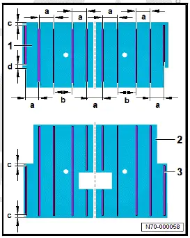
- Using hand-cartridge gun - V.A.G 1628- , apply 1-component assembly adhesive ⇒ Electronic parts catalogue (ETKA) in beads -3- of 6 mm in diameter to roof reinforcements -1- and -2- in accordance with the following dimensions:
- Dimension -a- = 95 mm
- Dimension -b- = 105 mm
- Dimension -c- = 20 mm
- Dimension -d- = 21 mm
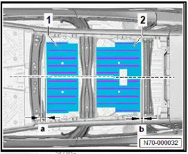
- Position front roof reinforcement -1- according to dimension -a- centrally on roof, and press it on across entire surface.
- Dimension -a- = 56 +- 3 mm from rear sheet-metal edge.
- Position rear roof reinforcement -2- according to dimension -b- centrally on roof; and press it on across entire surface.
- Dimension -b-: 24 +- 3 mm from front sheet-metal edge.
- Install moulded headliner ⇒ Rep. gr. 70 ; Removing and installing moulded headliner .
Was this page helpful?