Headlights
- Assembly overview - headlight, ECO
- Assembly overview - headlight, Performance
- Removing and installing headlight
- Removing and installing front turn signal bulb [M5]/[M7], ECO headlights
- Removing and installing headlight range control motor [V48]/[V49], ECO headlights
- Removing and installing headlight range control motor [V48]/[V49], Performance headlights
- Removing and installing LED module for daytime running light and side light [L176]/[L177]
- Removing and installing bulb for VARILIS headlight [L207]/[L208]
- Removing and installing headlight fan [V407]/[V408]
- Removing and installing output module 1 for LED headlight [A27]/[A31]
- Removing and installing LED module for daytime running lights [L377]/[L378]
Assembly overview - headlight, ECO
Assembly overview - headlight
Overview shows left side of vehicle as an example
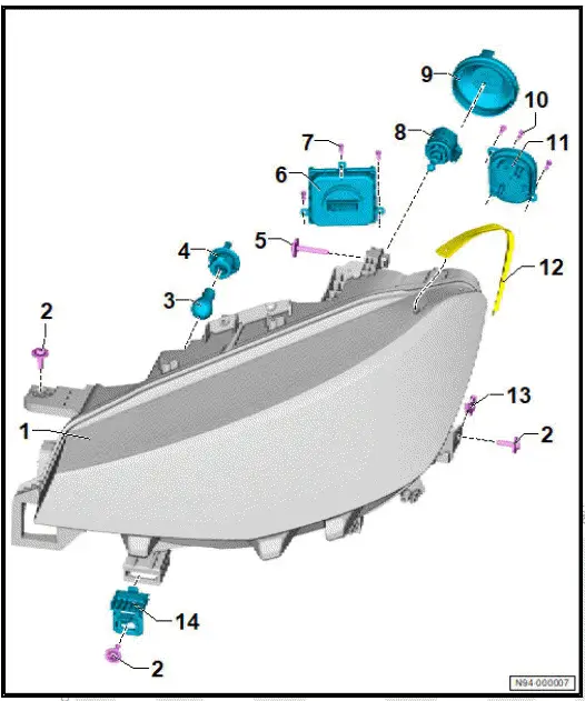
- Front left headlight - MX1- / front right headlight - MX2-
- Adjusting headlight ⇒ Maintenance ; Booklet ; Descriptions of work
- ⇒ Rep. gr. 94 ; Removing and installing headlight
- Bolt
- Qty. 3
- 4,5 N·m
- Front left turn signal bulb - M5- / front right turn signal bulb - M7-
- ⇒ Rep. gr. 94 ; Removing and installing front turn signal bulb [M5]/[M7]
- Grip for front turn signal bulb - M5- / -M7-
- Bolt
- 3,6 N·m
- Output module 1 for left LED headlight - A31- / output module 1 for right LED headlight - A27-
- ⇒ Rep. gr. 94 ; Removing and installing output module 1 for LED headlight [A27]/ [A31]
- Bolt
- Qty. 3
- 1,5 N·m
- Left headlight range control motor - V48- / right headlight range control motor - V49-
- ⇒ Rep. gr. 94 ; Removing and installing headlight range control motor [V48]/[V49]
- Housing cover for headlight range control motor
- To be used in event of repairs
- Bolt
- Qty. 3
- 1,5 N·m
- Left LED module for daytime running light and side light - L176- / right LED module for daytime running light and side light - L177-
- ⇒ "2.10 Removing and installing LED module for daytime running light and side light [L176]/[L177]"
- Gasket
- Speed nut
- M6
- Headlight mounting
Assembly overview - headlight, Performance
Assembly overview - headlight
Overview shows left side of vehicle as an example
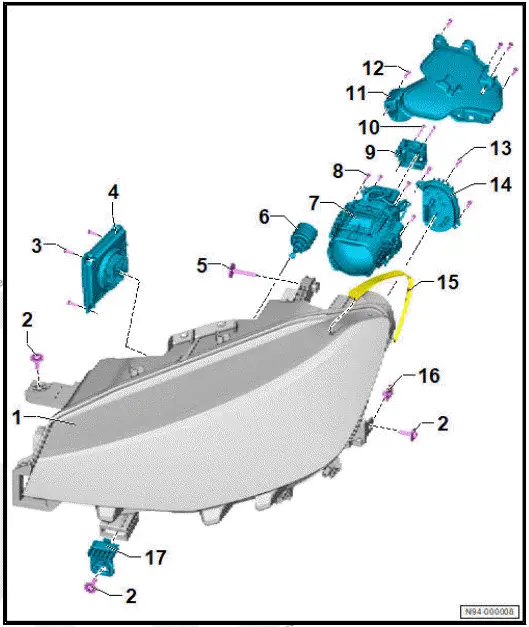
- Front left headlight - MX1- / front right headlight - MX2-
- ⇒ Maintenance ; Booklet ; Headlight setting: Checking headlight
- ⇒ Rep. gr. 94 ; Removing and installing headlight
- Bolt
- Qty. 3
- 4,5 N·m
- Bolt
- Qty. 3
- 1,5 N·m
- Output module 1 for left LED headlight - A31- / output module 1 for right LED headlight - A27-
- ⇒ Rep. gr. 94 ; Removing and installing output module 1 for LED headlight [A27]/ [A31]
- Bolt
- 3,6 N·m
- Left headlight range control motor - V48- / right headlight range control motor - V49-
- ⇒ Rep. gr. 94 ; Removing and installing headlight range control motor [V48]/[V49]
- Bulb for left VARILIS headlight - L207- / bulb for right VARILIS headlight - L208- ❑ ⇒ "2.11 Removing and installing bulb for VARILIS headlight [L207]/[L208]"
- Bolt
- Qty. 4
- 1,5 N·m
- Left headlight fan - V407- / right headlight fan - V408-
- ⇒ "2.12 Removing and installing headlight fan [V407]/[V408]"
- Bolt
- Qty. 2
- 1,5 N·m
- Housing cover
- To be used in event of repairs
- Bolt
- To be used in event of repairs
- Qty. 5
- 1,5 N·m
- Bolt
- Qty. 3
- 1,5 N·m
- Left LED module for daytime running light and side light - L176- / right LED module for daytime running light and side light - L177-
- With front left turn signal bulb - M5- / front right turn signal bulb - M7-
- ⇒ "2.10 Removing and installing LED module for daytime running light and side light [L176]/[L177]"
- Gasket
- Speed nut
- Headlight mounting
Assembly overview - LED module for daytime running light
Overview shows left side of vehicle as an example
- Left LED module for daytime running lights - L377- / right LED module for daytime running lights - L378-
- ⇒ "2.15 Removing and installing LED module for daytime running lights [L377]/[L378]"
- Bolt
- Qty. 3
- 2,5 N·m

Removing and installing headlight
Front left headlight - MX1- and front right headlight - MX2- are referred to hereafter as headlight.
Removing
- Remove bumper cover ⇒ General body repairs, exterior; Rep. gr. 63 ; Front bumper; Removing and installing bumper cover .
- Remove bracket for control unit for break-in protection.
Headlight on driver side
- Pull off Bowden cable coupling from headlight ⇒ General body repairs, exterior; Rep. gr. 55 ; Bonnet; Removing and installing Bowden cable .
All vehicles (continued)
- Unscrew bolts -2-.
- Disconnect electrical connector -3-.
- Remove headlight -1-.

Installing
Install in the reverse order of removal, observing the following:
- Push headlight into guide mountings.
- Check headlight adjustment and adjust headlights ⇒ Maintenance ; Booklet ; Descriptions of work .
Tightening torques
- ⇒ Rep. gr. 94 ; Assembly overview - headlight
Removing and installing front turn signal bulb [M5]/[M7], ECO headlights
Removing and installing front turn signal bulb [M5]/[M7]
Front left turn signal bulb - M5- and front right turn signal bulb - M7- are referred to hereafter as turn signal bulb.
Removal and installation are described for the left vehicle side as an example.
For reasons of clarity, the following work procedure is shown with the front left headlight - MX1- removed.
Removing
NOTICE
Risk of damage to turn signal bulb.
- Do not touch the glass part of the turn signal bulb with bare fingers. Wear clean fabric gloves, for example, when removing and installing the turn signal bulb.
- Release grip with turn signal bulb -1- in direction of -arrow-.
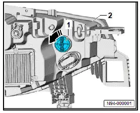
- Push turn signal bulb -2- slightly into grip -1-.
- Release turn signal bulb -2- in direction of -arrow-.
- Remove turn signal bulb -2- from grip -1-.

Installing
Install in reverse order of removal.
Removing and installing front turn signal bulb [M5]/[M7], Performance headlights
Removing and installing front turn signal bulb [M5]/[M7]
The front left turn signal bulb - M5- and front right turn signal bulb - M7- will henceforth be referred to as "turn signal bulb".
The left LED module for daytime running light and side light - L176- and right LED module for daytime running light and side light - L177- will henceforth be referred to as LED module for daytime running light.
Note
The front turn signal bulb and LED module for daytime running lights form a unit and cannot be removed separately
- ⇒ Rep. gr. 94 ; Removing and installing LED module for daytime running light and side light [L176]/[L177] .
Installing repair kit for headlight housing
Front left headlight - MX1- and front right headlight - MX2- are referred to hereafter as headlight.
The description focuses on one headlight version for demonstration purposes.
Note
Different repair kits are available ⇒ Electronic parts catalogue (ETKA) .
Removing
- Remove headlight with damaged retaining tab ⇒ Rep. gr. 94 ; Removing and installing headlight .
- Remove remains of damaged retaining tab.
Installing
- Fit retaining tab -3- of repair kit to headlight -1-.
- Tighten bolts -2-.

Further installation is carried out in reverse order of removal, observing the following:
- Install headlight and align it flush to body contour.
- Check headlight adjustment and adjust headlights ⇒ Maintenance ; Booklet ; Descriptions of work .
Removing and installing headlight range control motor [V48]/[V49], ECO headlights
Removing and installing headlight range control motor [V48]/[V49]
Special tools and workshop equipment required
- ESD workplace - VAS 6613-
Front left headlight - MX1- and front right headlight - MX2- are referred to hereafter as headlight.
Left headlight range control motor - V48- and right headlight range control motor - V49- are referred to hereafter as control motor.
Removal and installation are described for the left vehicle side as an example.
Removing
- Remove headlight ⇒ Rep. gr. 94 ; Removing and installing headlight .
NOTICE
Risk of damage to electrical components.
Electrostatic charge may damage electrical components.
- Work on electrical components must always be carried out at an ESD workplace.
- Place headlight on ESD workplace - VAS 6613
- Turn height adjustment screws at top of headlight as far as stop towards right.
- Use a hammer to carefully release housing cover -1- along predetermined break line -2-.
- Remove housing cover -1- from headlight.
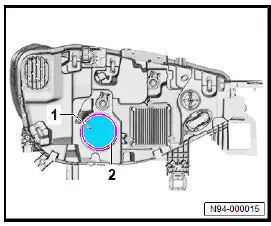
- Release control motor -1-:
- On left headlight, turn in direction of -arrow-.
- for right headlight, turn in opposite direction of -arrow-.
- Swing left headlight range control motor -1- downwards so that the ball head is pushed upwards out of ball head mounting -2-.
- Pull control motor -1- towards rear out of headlight.
- Disconnect electrical connector -3-.
- Remove control motor -1-.
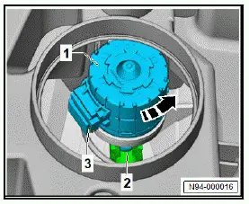
Installing
Install in the reverse order of removal, observing the following:
- Pull ball head mounting towards rear.
- Engage ball head on control motor into ball head mounting in headlight.
NOTICE
Risk of destroying headlight due to ingress of water.
- When installing the housing covers -1-, make sure that the seal is correctly seated.
Note
A new housing cover -1- must be used only, if the repair is carried out for the first time.
- Fit housing cover -1- on headlight.
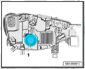
- Check headlight adjustment and adjust headlights ⇒ Maintenance ; Booklet ; Descriptions of work .
Tightening torques
- ⇒ Rep. gr. 94 ; Assembly overview - headlight
Removing and installing headlight range control motor [V48]/[V49], Performance headlights
Removing and installing headlight range control motor [V48]/[V49]
Special tools and workshop equipment required
- ESD workplace - VAS 6613-
Front left headlight - MX1- and front right headlight - MX2- are referred to hereafter as headlight.
Left headlight range control motor - V48- and right headlight range control motor - V49- are referred to hereafter as control motor.
Removal and installation are described for the left vehicle side as an example.
Removing
- Remove headlight ⇒ Rep. gr. 94 ; Removing and installing headlight .
NOTICE
Risk of damage to electrical components.
Electrostatic charge may damage electrical components.
- Work on electrical components must always be carried out at an ESD workplace.
- Place headlight on ESD workplace - VAS 6613- .
- Turn height adjustment screws of headlight to stop towards right.
- Use a hammer to carefully release housing cover -1- along predetermined break line -2-.
- Remove housing cover -1- from headlight.

- Release control motor -2-:
- On left headlight, turn in direction of -arrow-.
- for right headlight, turn in opposite direction of -arrow-.

- Swing left headlight range control motor -2- downwards so that the ball head is pushed upwards out of ball head mounting -1-.
- Pull control motor -2- towards rear out of headlight.
- Disconnect electrical connector -3-.
- Remove control motor -2-.
Installing
Install in the reverse order of removal, observing the following:
- Pull ball head mounting towards rear.
- Engage ball head on control motor into ball head mounting in headlight.
NOTICE
Risk of destroying headlight due to ingress of water.
- When installing the housing cover -1-, make sure that the seal is correctly seated.
Note
A new housing cover -1- must be used only, if the repair is carried out for the first time.
- Fit housing cover -1- on headlight.
- Tighten bolts -2-.
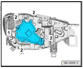
- Check headlight adjustment and adjust headlights ⇒ Maintenance ; Booklet ; Descriptions of work .
Tightening torques
- ⇒ Rep. gr. 94 ; Assembly overview - headlight
Removing and installing LED module for daytime running light and side light [L176]/[L177]
Special tools and workshop equipment required
- ESD workplace - VAS 6613-
Front left headlight - MX1- and front right headlight - MX2- are referred to hereafter as headlight.
Left LED module for daytime running light and side light - L176- and right LED module for daytime running light and side light - L177- are referred to hereafter as LED module for daytime running light.
Removal and installation are described for the left vehicle side as an example.
Removing
- Remove headlight ⇒ Rep. gr. 94 ; Removing and installing headlight .
NOTICE
Risk of damage to electrical components.
Electrostatic charge may damage electrical components.
- Work on electrical components must always be carried out at an ESD workplace.
- Place headlight on ESD workplace - VAS 6613- .
- Unscrew bolts -2-.
- Guide LED module for daytime running light -1- out of headlight housing.
- Disconnect electrical connector.
- Remove LED module for daytime running -1-.

Installing
Install in the reverse order of removal, observing the following:
NOTICE
Risk of destroying headlight due to ingress of water.
- Check seal between LED module for daytime running and headlight for damage.
- Ensure proper seating of gasket.
- Check headlight settings and adjust headlights if necessary ⇒ Maintenance ; Booklet 53.1 ; Descriptions of work .
Tightening torques
- ⇒ Rep. gr. 94 ; Assembly overview - headlight
Removing and installing bulb for VARILIS headlight [L207]/[L208]
Special tools and workshop equipment required
- ESD workplace - VAS 6613-
Front left headlight - MX1- and front right headlight - MX2- are referred to hereafter as headlight.
Bulb for left VARILIS headlight - L207- and bulb for right VARILIS headlight - L208- are referred to hereafter as bulb.
Removal and installation are described for the left vehicle side as an example
Removing
- Remove headlight ⇒ Rep. gr. 94 ; Removing and installing headlight .
NOTICE
Risk of damage to electrical components.
Electrostatic charge may damage electrical components.
- Work on electrical components must always be carried out at an ESD workplace.
- Place headlight on ESD workplace - VAS 6613- .
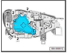
- Use a hammer to carefully release housing cover -1- along predetermined break line -2-.
- Remove housing cover -1- from headlight.

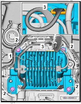
- Disconnect electrical connector -2-.
- Pull off retainer for electrical wires -4-.
- Release locking devices -3-.
- Remove electrical wires from retainer -1-.
- Release locking devices -6-.
- Remove electrical connector -5-.
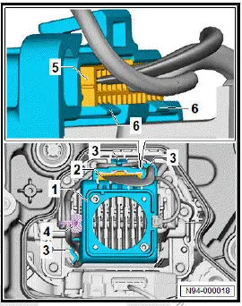
- Unscrew bolts -2-.
- Guide out bulb -1- from headlight housing.
- Disconnect electrical connector -3-.
- Remove bulb -1-.
Installing
Install in the reverse order of removal, observing the following:
NOTICE
Risk of destroying headlight due to ingress of water.
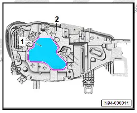
- When installing the housing cover -1-, make sure that the seal is correctly seated.
Note
A new housing cover -1- must be used only, if the repair is carried out for the first time.
- Fit housing cover -1- on headlight.
- Tighten bolts -2-.
- Check headlight settings and adjust headlights if necessary ⇒ Maintenance ; Booklet 53.1 ; Descriptions of work .
Tightening torques
- ⇒ Rep. gr. 94 ; Assembly overview - headlight
Removing and installing headlight fan [V407]/[V408]
Special tools and workshop equipment required
- ESD workplace - VAS 6613-
Front left headlight - MX1- and front right headlight - MX2- are referred to hereafter as headlight.
Left headlight fan - V407- and right headlight fan - V408- are referred to hereafter as fan.
Removal and installation are described for the left vehicle side as an example.
Removing
- Remove headlight ⇒ Rep. gr. 94 ; Removing and installing headlight .
NOTICE
Risk of damage to electrical components.
Electrostatic charge may damage electrical components.
- Work on electrical components must always be carried out at an ESD workplace.
- Place headlight on ESD workplace - VAS 6613- .
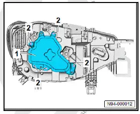
- Use a hammer to carefully release housing cover -1- along predetermined break line -2-.
- Remove housing cover -1- from headlight.
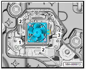
- Unscrew bolts -2-.
- Disconnect electrical connector -3-.
- Remove fan -1-.
Installing
Install in the reverse order of removal, observing the following:
NOTICE
Risk of destroying headlight due to ingress of water.
- When installing the housing cover -1-, make sure that the seal is correctly seated.
Note
A new housing cover -1- must be used only, if the repair is carried out for the first time
- Fit housing cover -1- on headlight.
- Tighten bolts -2-.
- Check headlight settings and adjust headlights if necessary ⇒ Maintenance ; Booklet 53.1 ; Descriptions of work .
Tightening torques
- ⇒ Rep. gr. 94 ; Assembly overview - headlight
Removing and installing output module 1 for LED headlight [A27]/[A31]
Front left headlight - MX1- and front right headlight - MX2- are referred to hereafter as headlight.
Output module 1 for left LED headlight - A31- and output module 1 for right LED headlight - A27- are referred to hereafter as output module.
Removing
If output module is renewed:
- Carry out required function/functions using ⇒ Vehicle diagnostic tester ⇒ Rep. gr. 00 ; Access to diagnoses .
Continued
- Unscrew bolts -1-.
- Pull off output module -2- from headlight.

Installing
Install in the reverse order of removal, observing the following:
NOTICE
Risk of destroying headlight due to ingress of water.
- Check seal between output module and headlight for damage.
- Make sure seal is properly seated.
- Check headlight settings and adjust headlights if necessary ⇒ Maintenance ; Booklet 53.1 ; Descriptions of work .
Tightening torques
- ⇒ Rep. gr. 94 ; Assembly overview - headlight
Removing and installing light conductor for contour lighting in radiator grille [L362]/[L363]
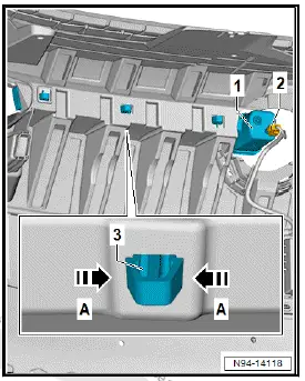
The light conductor for contour lighting in radiator grille, front left - L363- / light conductor for contour lighting in radiator grille, front right - L362- will henceforth be referred to as "light conductor".
Removing
- Remove front badge ⇒ General body repairs, exterior; Rep.gr. 66 ; Lettering and badges; Removing and installing front badge .
- Disconnect electrical connector -2-.
- Release retaining clips -3- in direction of -arrow A-.
- Pull out light conductor -1-.
Installing
Install in the reverse order of removal, observing the following:
- The light conductor must be heard to engage.
Removing and installing LED module for daytime running lights [L377]/[L378]
Left LED module for daytime running lights - L377- and right LED module for daytime running lights - L378- are referred to hereafter as LED module for daytime running light.
Removal and installation are described for the left vehicle side as an example.
Removing
- Remove front left wheel housing liner ⇒ General body repairs, exterior; Rep. gr. 66 ; Wheel housing liner; Removing and installing front wheel housing liner .
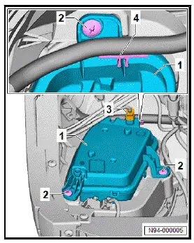
- Disconnect electrical connector -3-.
- Pull off retainer for electrical wire -4-.
- Unscrew bolts -2-.
- Remove LED module for daytime running -1-.
Installing
Install in the reverse order of removal, observing the following:
Tightening torques
- ⇒ Rep. gr. 94 ; Assembly overview - LED module for daytime running light