Refrigerant circuit, R134a/R1234yf
- System overview - refrigerant circuit
- Assembly overview - refrigerant lines
- Assembly overview - heat exchanger for high-voltage battery
- Assembly overview - condenser
- Removing and installing refrigerant pressure and temperature sender [G395]
- Removing and installing pressure sender for refrigerant circuit G805
- Detaching and attaching refrigerant line at expansion valve
- Removing and installing desiccant bag
- Removing and installing evacuating and charging valve (low-pressure and high-pressure sides)
- Removing and installing refrigerant expansion valve 1 N636
- Removing and installing heat exchanger for high-voltage battery
- Removing and installing refrigerant shut-off valve for heater and air conditioner unit [N541], left-hand drive vehicles
- Removing and installing refrigerant shut-off valve for heater and air conditioning unit N541 - right-hand drive vehicles
- Removing and installing refrigerant lines
- Removing and installing refrigerant line from condenser to air conditioner compressor [VX81]
- Removing and installing refrigerant line from heat exchanger for high-voltage battery to high-pressure line
- Removing and installing refrigerant line from heat exchanger for high-voltage battery to low-pressure line
- Detaching and attaching refrigerant lines at condenser
- Cleaning refrigerant circuit
System overview - refrigerant circuit
- Air conditioner compressor - VX81-
- ⇒ Rep. gr. 87 ; Removing and installing air conditioner compressor [VX81]
- Refrigerant pressure and temperature sender - G395-
- ⇒ Rep. gr. 87 ; Removing and installing refrigerant pressure and temperature sender [G395]
- Service connection, lowpressure side
- ⇒ Rep. gr. 87 ; Removing and installing evacuating and charging valve (low-pressure and high-pressure sides)
- Evaporator
- ⇒ Rep. gr. 87 ; Removing and installing evaporator
- Expansion valve
- ⇒ Rep. gr. 87 ; Removing and installing expansion valve
- Refrigerant shut-off valve for heater and air conditioning unit - N541-
- ⇒ Rep. gr. 87 ; Removing and installing refrigerant shut-off valve for heater and air conditioning unit [N541]
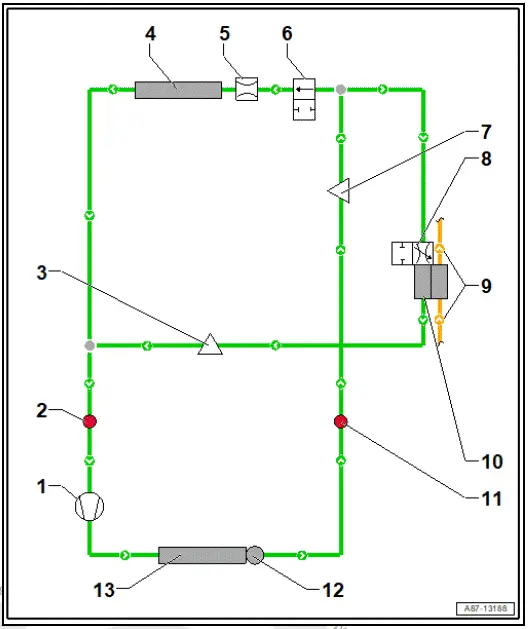
- Service connection, high-pressure side
- ⇒ Rep. gr. 87 ; Removing and installing evacuating and charging valve (low-pressure and high-pressure sides)
- Refrigerant expansion valve 1 - N636
- ⇒ Rep. gr. 87 ; Removing and installing refrigerant expansion valve 1 N636
- Incorporation in high-voltage battery coolant circuit
- ⇒ Electric drive motor; Rep. gr. 19 ; Cooling system/coolant; Connection diagram - coolant hoses
- Heat exchanger for high-voltage battery
- ⇒ Rep. gr. 87 ; Removing and installing heat exchanger for high-voltage battery
- Pressure sender for refrigerant circuit - G805-
- ⇒ Rep. gr. 87 ; Removing and installing pressure sender for refrigerant circuit [G805]
- Dryer with receiver
- ⇒ Rep. gr. 87 ; Removing and installing desiccant bag
- Condenser
- ⇒ Rep. gr. 87 ; Removing and installing condenser
Assembly overview - refrigerant lines
- Bolt
- Applies to all connections in illustration ❑ 8 N·m
- Seal
- Applies to all connections in illustration
- Renew after removing
- Refrigerant line
- ⇒ Rep. gr. 87 ; Removing and installing refrigerant line from condenser to expansion valve
- Pressure sender for refrigerant circuit - G805-
- ⇒ Rep. gr. 87 ; Removing and installing pressure sender for refrigerant circuit G805
- 8 N·m
- Seal
- Renew after removing
- Valve core
- 0,6 N·m
- Refrigerant shut-off valve for heater and air conditioning unit - N541-
- ⇒ Rep. gr. 87 ; Removing and installing refrigerant shut-off valve for heater and air conditioning unit N541
- Union nut
- 16,5 N·m
9 - Evacuating and charging valve (high-pressure side)
- ⇒ Rep. gr. 87 ; Removing and installing evacuating and charging valve (low-pressure and high-pressure sides)
- 2,2 N·m
- Valve cap (high pressure)
- Refrigerant line
- ⇒ Rep. gr. 87 ; Removing and installing refrigerant line from heat exchanger for high-voltage battery to high-pressure line
- Retainer
- Refrigerant line
- ⇒ Rep. gr. 87 ; Removing and installing refrigerant line from air conditioner compressor VX81 to expansion valve
- Expansion valve
- ⇒ Rep. gr. 87 ; Assembly overview - evaporator housing
- ⇒ Rep. gr. 87 ; Removing and installing expansion valve
- Seal

- Renew after removing
- Refrigerant pressure and temperature sender - G395
- ⇒ Rep. gr. 87 ; Removing and installing refrigerant pressure and temperature sender G395
- 10 N·m
- Valve cap (low pressure)
- Evacuating and charging valve (low-pressure side)
- ⇒ Rep. gr. 87 ; Removing and installing evacuating and charging valve (low-pressure and high-pressure sides)
- 2,2 N·m
- Refrigerant line
- ⇒ Rep. gr. 87 ; Removing and installing refrigerant line from heat exchanger for high-voltage battery to low-pressure line
- Bolt
- 2x
- 20 N·m
- Air conditioner compressor - VX81-
- ⇒ Rep. gr. 87 ; Assembly overview - air conditioner compressor
- ⇒ Rep. gr. 87 ; Removing and installing air conditioner compressor VX81
- Refrigelinerant
- ⇒ Rep. gr. 87 ; Removing and installing refrigerant line from condenser to air conditioner compressor VX81
- Condenser
- ⇒ Rep. gr. 87 ; Assembly overview - condenser
- ⇒ Rep. gr. 87 ; Removing and installing condenser
- High-voltage battery heat exchanger
- ⇒ Rep. gr. 87 ; Assembly overview - heat exchanger for high-voltage battery
- ⇒ Rep. gr. 87 ; Removing and installing heat exchanger for high-voltage battery
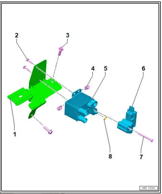
Assembly overview - heat exchanger for high-voltage battery
- Bracket
- Bolt
- 2x
- 8 N·m
- Bolt
- 2x
- 20 N·m
- Lock nut
- 2x
- High-voltage battery heat exchanger
- ⇒ Rep. gr. 87 ; Removing and installing heat exchanger for high-voltage battery
- Refrigerant expansion valve 1 - N636-
- ⇒ Rep. gr. 87 ; Removing and installing refrigerant expansion valve 1 N636
- Bolt
- 8 N·m
- Oil seal
- Renew after removing
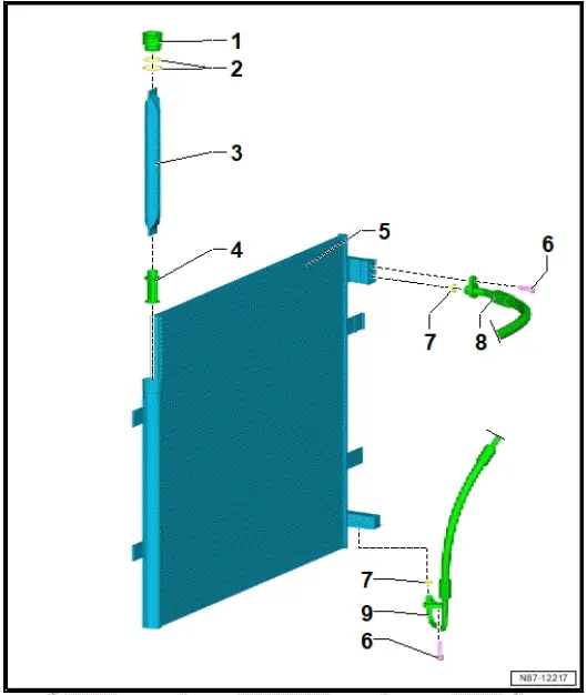
Assembly overview - condenser
- Plug
- Renew after removing ❑ 10 N·m
- Oil seal
- 2x
- Renew after removing
- Desiccant bag
- Renew after removing
- ⇒ Rep. gr. 87 ; Removing and installing desiccant bag/dryer
- Filter
- Renew after removing
- Condenser
- ⇒ Rep. gr. 87 ; Removing and installing condenser
- Bolt
- 8 N·m
- Oil seal
- ⇒ Rep. gr. 87 ; Assembly overview - refrigerant lines
- Refrigerant line
- ⇒ Rep. gr. 87 ; Assembly overview - refrigerant lines
- Refrigerant line
- ⇒ Rep. gr. 87 ; Assembly overview - refrigerant lines
Removing and installing refrigerant pressure and temperature sender [G395]
Special tools and workshop equipment required
- engine bung set - VAS 6122-
- socket - T40284-
Removing
- Immediately seal open lines and connections with clean plugs from engine bung set - VAS 6122- .
- ⇒ General information, air conditioning systems with refrigerant R134a/R1234yf; Rep. gr. 87 ; Working with air conditioner service station; Draining refrigerant circuit .
- Detach coolant expansion tank, and lay it aside ⇒ Rep. gr. 19 ; Cooling system/coolant; Removing and installing coolant expansion tank .
- Disconnect electrical connector -1-.
- Check connection of refrigerant line -4- and refrigerant pressure and temperature sender - G395- -2- for contamination and clean.
CAUTION
Risk of frostbite from escaping pressurised refrigerant Risk of frostbite on skin and other parts of the body
- Put on protective gloves.
- Put on safety goggles.
- Extract/drain refrigerant and then immediately open up refrigerant circuit.
- Extract/drain refrigerant again if more than 10 minutes have passed since initial extraction and refrigerant circuit has not been opened up. Renewed evaporation has created pressure in the refrigerant circuit.
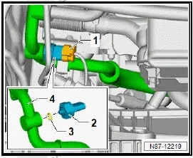
- Unscrew sender -2- using socket - T40284- while counterholding at refrigerant line -4- with open-end spanner
Installing
Install in reverse order of removal, observing the following:
- ⇒ General information, air conditioning systems with refrigerant R134a/R1234yf; Rep. gr. 87 ; Working with air conditioner service station; Charging refrigerant circuit .
Tightening torques
- ⇒ Rep. gr. 87 ; Assembly overview - refrigerant lines
Removing and installing pressure sender for refrigerant circuit G805
Special tools and workshop equipment required
- engine bung set - VAS 6122-
- socket - T40284-
Removing
Seal open lines and connections immediately with clean plugs from engine bung set - VAS 6122- .
- Unfasten coolant expansion tank and move to side ⇒ Rep. gr. 19 ; Cooling system/coolant; Removing and installing coolant expansion tank .
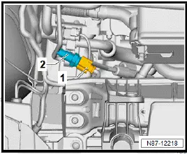
- Unplug electrical connector -1-.
- Check connection of refrigerant line and pressure sender for refrigerant circuit - G805- -2- for dirt and clean if necessary.
CAUTION
Risk of frostbite from escaping pressurised refrigerant Risk of frostbite on skin and other parts of the body
- Put on protective gloves.
- Put on safety goggles.
- If refrigerant escapes from the refrigerant line for more than 1 second when the pressure sender is unfastened, tighten the pressure sender and renew the defective nonreturn valve.
- Extract/drain refrigerant and then immediately open up refrigerant circuit.
- Remove sender -2- using socket - T40284- .
Installing
Installation is carried out in reverse order; note the following:
Tightening torques
- ⇒ Rep. gr. 87 ; Assembly overview - refrigerant lines
Removing and installing expansion valve
Special tools and workshop equipment required
- engine bung set - VAS 6122-
Removing
Seal open lines and connections immediately with clean plugs from engine bung set - VAS 6122- .
- ⇒ General information - Air conditioners with refrigerant R134a/R1234yf; Rep. gr. 87 ; Working with the air conditioner service station; Discharging refrigerant circuit .
- Detach refrigerant lines from expansion valve ⇒ Rep. gr. 87 ; Detaching and attaching refrigerant line at expansion valve .
- Remove bolts -1- and -2-.
- Remove expansion valve -3-.

Installing
Installation is carried out in reverse order; note the following:
- ⇒ General information - Air conditioners with refrigerant R134a/R1234yf; Rep. gr. 87 ; Working with the air conditioner service station; Charging refrigerant circuit .
Tightening torques
- ⇒ Rep. gr. 87 ; Assembly overview - evaporator housing
Detaching and attaching refrigerant line at expansion valve
Special tools and workshop equipment required
- engine bung set - VAS 6122-
Removing
Seal open lines and connections immediately with clean plugs from engine bung set - VAS 6122- .
- ⇒ General information - Air conditioners with refrigerant R134a/R1234yf; Rep. gr. 87 ; Working with the air conditioner service station; Discharging refrigerant circuit .
- Remove air intake box of heater and air conditioning unit ⇒ Rep. gr. 87 ; Removing and installing air intake box of heater and air conditioning unit .
CAUTION
Risk of frostbite from escaping pressurised refrigerant Risk of frostbite on skin and other parts of the body
- Put on protective gloves.
- Put on safety goggles.
- Extract/drain refrigerant and then immediately open up refrigerant circuit.
- Extract/drain refrigerant again if more than 10 minutes have passed since initial extraction and refrigerant circuit has not been opened up. Renewed evaporation has created pressure in the refrigerant circuit.
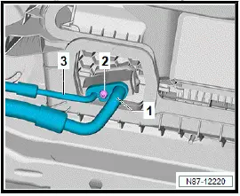
- Remove bolt -2-.
- Detach refrigerant lines -1- and -3-.
Installing
Installation is carried out in reverse order; note the following:
- ⇒ General information - Air conditioners with refrigerant R134a/R1234yf; Rep. gr. 87 ; Working with the air conditioner service station; Charging refrigerant circuit .
Tightening torques
- ⇒ Rep. gr. 87 ; Assembly overview - refrigerant lines
Removing and installing condenser
Special tools and workshop equipment required
- engine bung set - VAS 6122-
Removing
Seal open lines and connections immediately with clean plugs from engine bung set - VAS 6122- .
- ⇒ General information - Air conditioners with refrigerant R134a/R1234yf; Rep. gr. 87 ; Working with the air conditioner service station; Discharging refrigerant circuit .
- Disassemble radiator module ⇒ Rep. gr. 19 ; Radiator/radiator fans; Dismantling and assembling radiator module .
Installing
Installation is carried out in reverse order; note following:
If condenser is renewed:
- Adjust quantity of refrigerant oil and, if necessary, clean refrigerant circuit ⇒ Air conditioners with refrigerant R134a - General information; Rep. gr. 87 ; Renewing components .
Continued
- ⇒ General information - Air conditioners with refrigerant R134a/R1234yf; Rep. gr. 87 ; Working with the air conditioner service station; Charging refrigerant circuit .
Tightening torques
- ⇒ Rep. gr. 87 ; Assembly overview - condenser
Removing and installing desiccant bag
Special tools and workshop equipment required
- engine bung set - VAS 6122-
Removing
Seal open lines and connections immediately with clean plugs from engine bung set - VAS 6122- .
- ⇒ General information - Air conditioners with refrigerant R134a/R1234yf; Rep. gr. 87 ; Working with the air conditioner service station; Discharging refrigerant circuitCAUTION
- Remove condenser ⇒ Rep. gr. 87 ; Removing and installing condenser .
CAUTION
Risk of frostbite from escaping pressurised refrigerant Risk of frostbite on skin and other parts of the body
- Put on protective gloves.
- Put on safety goggles.
- Extract/drain refrigerant and then immediately open up refrigerant circuit.
- Extract/drain refrigerant again if more than 10 minutes have passed since initial extraction and refrigerant circuit has not been opened up. Renewed evaporation has created pressure in the refrigerant circuit.
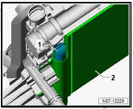
- Remove plug -1- from condenser -2-.

- Take desiccant bag -1- out of condenser -2-.
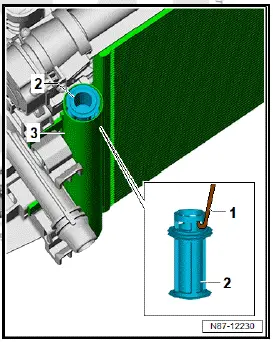
- Pull filter -2- out of condenser -3- using a piece of wire -1-.
Installing
Installation is carried out in reverse order; note the following:
- Check that threads and sealing surfaces of condenser are not dirty or damaged.
- ⇒ General information - Air conditioners with refrigerant R134a/R1234yf; Rep. gr. 87 ; Working with the air conditioner service station; Charging refrigerant circuit .
Tightening torques
- ⇒ Rep. gr. 87 ; Assembly overview - condenser
Removing and installing evacuating and charging valve (low-pressure and high-pressure sides)
Special tools and workshop equipment required
- engine bung set - VAS 6122-
- socket - T10364/4ARemoving
Immediately seal open lines and connections with clean plugs from engine bung set - VAS 6122- .
- ⇒ General information, air conditioning systems with refrigerant R134a/R1234yf; Rep. gr. 87 ; Working with air conditioner service station; Draining refrigerant circuit .
- Unscrew protective cap -3-.
CAUTION
Risk of frostbite from escaping pressurised refrigerant Risk of frostbite on skin and other parts of the body
- Put on protective gloves.
- Put on safety goggles.
- Extract/drain refrigerant and then immediately open up refrigerant circuit.
- Extract/drain refrigerant again if more than 10 minutes have passed since initial extraction and refrigerant circuit has not been opened up. Renewed evaporation has created pressure in the refrigerant circuit.
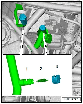
- Unscrew valve core -2- using socket - T10364/4A- .
Installing
Install in reverse order of removal, observing the following:
- ⇒ General information, air conditioning systems with refrigerant R134a/R1234yf; Rep. gr. 87 ; Working with air conditioner service station; Charging refrigerant circuit .
Tightening torques
- ⇒ Rep. gr. 87 ; Assembly overview - refrigerant lines
Removing and installing refrigerant expansion valve 1 N636
Special tools and workshop equipment required
- engine bung set - VAS 6122-
Removing
Immediately seal open lines and connections with clean plugs from engine bung set - VAS 6122- .
- ⇒ General information, air conditioning systems with refrigerant R134a/R1234yf; Rep. gr. 87 ; Working with air conditioner service station; Draining refrigerant circuit .
- Remove air intake box of heater and air conditioning unit ⇒ Rep. gr. 87 ; Removing and installing air intake unit of heater and air conditioning unit .
CAUTION
The cooling system may be under pressure. Risk of scalding due to hot steam and hot coolant Danger of scalding skin and other parts of the body
- Put on protective gloves.
- Put on safety goggles.
- Cover filler cap on expansion tank with a suitable cloth and open carefully to release pressure.
- Detach coolant expansion tank, and lay it slightly aside ⇒ Rep. gr. 19 ; Cooling system/coolant; Removing and installing coolant expansion tank .
CAUTION
Risk of frostbite from escaping pressurised refrigerant Risk of frostbite on skin and other parts of the body
- Put on protective gloves.
- Put on safety goggles.
- Extract/drain refrigerant and then immediately open up refrigerant circuit.
- Extract/drain refrigerant again if more than 10 minutes have passed since initial extraction and refrigerant circuit has not been opened up. Renewed evaporation has created pressure in the refrigerant circuit.
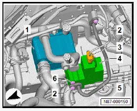
- Unscrew bolts -2-.
- Remove refrigerant lines -5-.
- Pull off electrical connector -3-.
- Unscrew bolt -6-.
- Pull refrigerant expansion valve 1 - N636- -4- off heat exchanger -1-.
Installing
Install in reverse order of removal, observing the following:
- ⇒ General information, air conditioning systems with refrigerant R134a/R1234yf; Rep. gr. 87 ; Working with air conditioner service station; Charging refrigerant circuit .
Tightening torques
- ⇒ Rep. gr. 87 ; Assembly overview - refrigerant lines
- ⇒ Rep. gr. 87 ; Assembly overview - heat exchanger for high-voltage battery
Removing and installing heat exchanger for high-voltage battery
Special tools and workshop equipment required
- cooling system service unit - VAS 531 011-
- engine bung set - VAS 6122-
- hose clamps up to 25 mm in dia. - 3094
Removing
Note
If the cooling system service unit - VAS 531 011- is used to conclude filling the cooling system, it is sufficient to clamp off the coolant hoses.
Immediately seal open lines and connections with clean plugs from engine bung set - VAS 6122- .
- ⇒ General information, air conditioning systems with refrigerant R134a/R1234yf; Rep. gr. 87 ; Working with air conditioner service station; Draining refrigerant circuit .
- Remove air intake box of heater and air conditioning unit ⇒ Rep. gr. 87 ; Removing and installing air intake unit of heater and air conditioning unit .
CAUTION
The cooling system may be under pressure. Risk of scalding due to hot steam and hot coolant Danger of scalding skin and other parts of the body
- Put on protective gloves.
- Put on safety goggles.
- Cover filler cap on expansion tank with a suitable cloth and open carefully to release pressure.
- Detach coolant expansion tank, and lay it aside ⇒ Rep. gr. 19 ; Cooling system/coolant; Removing and installing coolant expansion tank .
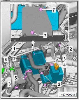
- Clamp off coolant hoses behind hose clips -5- using hose clamps up to 25 mm in dia. - 3094- .
- Place cleaning cloth under coolant connections on heat exchanger -1- to absorb escaping coolant.
- Separate hose clips -5- and pull off coolant hoses.

- Disconnect electrical connector -4-.
CAUTION
Risk of frostbite from escaping pressurised refrigerant Risk of frostbite on skin and other parts of the body
- Put on protective gloves.
- Put on safety goggles.
- Extract/drain refrigerant and then immediately open up refrigerant circuit.
- Extract/drain refrigerant again if more than 10 minutes have passed since initial extraction and refrigerant circuit has not been opened up. Renewed evaporation has created pressure in the refrigerant circuit.

- Disconnect electrical connector -4-.
CAUTION
Risk of frostbite from escaping pressurised refrigerant Risk of frostbite on skin and other parts of the body
- Put on protective gloves.
- Put on safety goggles.
- Extract/drain refrigerant and then immediately open up refrigerant circuit.
- Extract/drain refrigerant again if more than 10 minutes have passed since initial extraction and refrigerant circuit has not been opened up. Renewed evaporation has created pressure in the refrigerant circuit.
- Unscrew bolts -2-.
- Pull off refrigerant lines from heat exchanger -1-.
- Detach refrigerant line from bracket -6-.
- Unscrew bolts -3-.
- Remove heat exchanger -1- with bracket.
- Unscrew bolts -7-.
- Remove heat exchanger -1-.
Installing
Install in the reverse sequence of removal, observing the following:
If heat exchanger is renewed:
- Carry out adaption routine for refrigerant oil capacity ⇒ General information - air conditioning systems with refrigerant R134a/R1234yf; Rep. gr. 87 ; Renewing components; Renewing components .
Continued
- ⇒ General information; air conditioning systems with refrigerant R134a/R1234yf; Rep. gr. 87 ; Working with air conditioner service station; Charging refrigerant circuit
- ⇒ Rep. gr. 19 ; Cooling system/coolant; Filling cooling system .
Tightening torques
- ⇒ Rep. gr. 87 ; Assembly overview - refrigerant lines
- ⇒ Rep. gr. 87 ; Assembly overview - heat exchanger for high-voltage battery
Removing and installing refrigerant shut-off valve for heater and air conditioner unit [N541], left-hand drive vehicles
Special tools and workshop equipment required
- engine bung set - VAS 6122-
Removing
- Immediately seal open lines and connections with clean plugs from engine bung set - VAS 6122- .
- Remove air intake box of heater and air conditioning unit ⇒ Rep. gr. 87 ; Removing and installing air intake unit of heater and air conditioning unit .
- ⇒ General information, air conditioning systems with refrigerant R134a/R1234yf; Rep. gr. 87 ; Working with air conditioner service station; Draining refrigerant circuit .
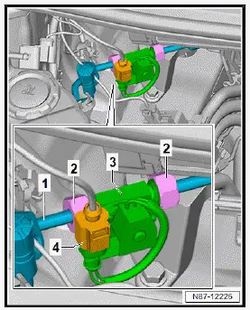
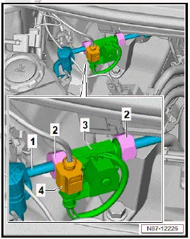
- Disconnect electrical connector -4-.
CAUTION
Risk of frostbite from escaping pressurised refrigerant Risk of frostbite on skin and other parts of the body
- Put on protective gloves.
- Put on safety goggles.
- Extract/drain refrigerant and then immediately open up refrigerant circuit.
- Extract/drain refrigerant again if more than 10 minutes have passed since initial extraction and refrigerant circuit has not been opened up. Renewed evaporation has created pressure in the refrigerant circuit.
- Loosen union nuts -2-. When doing this, counterhold on refrigerant shut-off valve for heater and air conditioner unit - N541- -3-.
- Detach refrigerant shut-off valve for heater and air conditioner unit - N541- -3-.
Installing
Install in reverse order of removal, observing the following:
- Make sure that refrigerant lines -1- are routed free of stress.
- When tightening union nuts, make sure that refrigerant lines -1- remain free of stress.
- Screw on union nuts -2- to stop by hand.
- Tighten union nuts -2-. When doing this, counterhold on refrigerant shut-off valve for heater and air conditioner unit - N541- -3-.
- Connect electrical connector -4-.
- ⇒ General information, air conditioning systems with refrigerant R134a/R1234yf; Rep. gr. 87 ; Working with air conditioner service station; Charging refrigerant circuit .
Tightening torques
- ⇒ Rep. gr. 87 ; Assembly overview - air intake box of heater and air conditioning unit
- ⇒ Rep. gr. 87 ; Assembly overview - refrigerant lines
Removing and installing refrigerant shut-off valve for heater and air conditioning unit N541 - right-hand drive vehicles
Special tools and workshop equipment required
- engine bung set - VAS 6122-
Removing
Seal open lines and connections immediately with clean plugs from engine bung set - VAS 6122- .
- ⇒ General information - Air conditioners with refrigerant R134a/R1234yf; Rep. gr. 87 ; Working with the air conditioner service station; Discharging refrigerant circuit .
- Remove refrigerant line leading from condenser to expansion valve ⇒ Rep. gr. 87 ; Removing and installing refrigerant line from condenser to expansion valve .
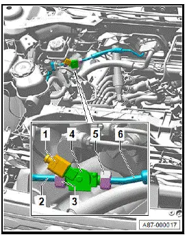
- Mark installation position between refrigerant shut-off valve for heater and air conditioning unit - N541- -3- and refrigerant line -1- before loosening union nuts.
- Loosen union nuts -2- while counterholding at shut-off valve -3-.
- Detach shut-off valve -3-.

Important
Before installing the refrigerant line in the vehicle, the refrigerant shut-off valve for heater and air conditioning unit - N541- -4- must be secured to the refrigerant line -2-.
- Screw refrigerant line -2- with union nut -3- onto shut-off valve -4- by hand and as far as stop; pay attention to marking for installation position when doing so.
- Tighten union nut -3- while counterholding at shut-off valve -4-.
- Install refrigerant line -2- with shut-off valve -4- and make sure it is routed so that it is free of stress ⇒ Rep. gr. 87 ; Removing and installing refrigerant line from condenser to expansion valve .
- Plug in electrical connector -1-.
- Install refrigerant line -6- between shut-off valve -4- and expansion valve; observe following sequence when doing so:
- Secure refrigerant line -6- to expansion valve ⇒ Rep.gr. 87 ; Detaching and attaching refrigerant line at expansion valve .
- Tighten union nut -5- while counterholding at shut-off valve -4-.
- When tightening union nut -5-, make sure that refrigerant lines -2- and -6- remain free of stress.
- ⇒ General information - Air conditioners with refrigerant R134a/R1234yf; Rep. gr. 87 ; Working with the air conditioner service station; Charging refrigerant circuit .
Tightening torques
- ⇒ Rep. gr. 87 ; Assembly overview - refrigerant lines
Removing and installing refrigerant lines
Removing and installing refrigerant line from condenser to expansion valve
Special tools and workshop equipment required
- engine bung set - VAS 6122-
Removing
Immediately seal open lines and connections with clean plugs from engine bung set - VAS 6122- .
- ⇒ General information, air conditioning systems with refrigerant R134a/R1234yf; Rep. gr. 87 ; Working with air conditioner service station; Draining refrigerant circuit .
- Remove air intake box of heater and air conditioning unit ⇒ Rep. gr. 87 ; Removing and installing air intake unit of heater and air conditioning unit .
- Remove front underbody cladding ⇒ General body repairs, exterior; Rep. gr. 66 ; Underbody cladding; Removing and installing front underbody cladding .
- Detach coolant expansion tank, and lay it aside ⇒ Rep.
gr. 19 ; Cooling system/coolant; Removing and installing coolant expansion tank .
CAUTION
Risk of frostbite from escaping pressurised refrigerant Risk of frostbite on skin and other parts of the body
- Put on protective gloves.
- Put on safety goggles.
- Extract/drain refrigerant and then immediately open up refrigerant circuit.
- Extract/drain refrigerant again if more than 10 minutes have passed since initial extraction and refrigerant circuit has not been opened up. Renewed evaporation has created pressure in the refrigerant circuit.
- Unscrew bolt -2-.
- Pull off refrigerant line -1-.
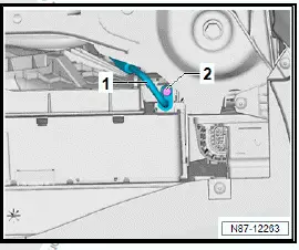
- Disconnect electrical connector -2-.
- Unhook refrigerant line -1- from bracket -3-.
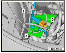
- Disconnect electrical connector -3-.
- Unscrew bolts -2-.
- Pull off refrigerant line -1-.
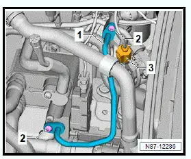
- Unscrew bolt -2-.
- Pull off refrigerant lines -3- from expansion valve.

- Remove refrigerant lines -1-.
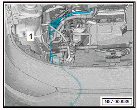
Installing
Install in reverse order of removal, observing the following:
- ⇒ General information, air conditioning systems with refrigerant R134a/R1234yf; Rep. gr. 87 ; Working with air conditioner service station; Charging refrigerant circuit .
Tightening torques
- ⇒ Rep. gr. 87 ; Assembly overview - refrigerant lines
- ⇒ Rep. gr. 87 ; Assembly overview - condenser
Removing and installing refrigerant line from air conditioner compressor to expansion valve
Special tools and workshop equipment required
- engine bung set - VAS 6122-
Removing
Seal open lines and connections immediately with clean plugs from engine bung set - VAS 6122- .
- ⇒ General information - Air conditioners with refrigerant R134a/R1234yf; Rep. gr. 87 ; Working with the air conditioner service station; Discharging refrigerant circuit .
- Remove air intake box of heater and air conditioning unit ⇒ Rep. gr. 87 ; Removing and installing air intake box of heater and air conditioning unit .
- Unfasten coolant expansion tank and move to side ⇒ Rep. gr. 19 ; Cooling system/coolant; Removing and installing coolant expansion tank .
CAUTION
Risk of frostbite from escaping pressurised refrigerant Risk of frostbite on skin and other parts of the body
- Put on protective gloves.
- Put on safety goggles.
- Extract/drain refrigerant and then immediately open up refrigerant circuit.
- Extract/drain refrigerant again if more than 10 minutes have passed since initial extraction and refrigerant circuit has not been opened up. Renewed evaporation has created pressure in the refrigerant circuit.
- Unscrew bolt -3- securing refrigerant line from air conditioner compressor to expansion valve.
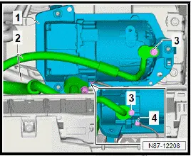
- Remove bolts -3-.
- Detach refrigerant line -2-.
- Unplug electrical connector -5-.
- Release refrigerant line -1- from retainer -4-.
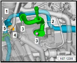
- Remove bolt -2-.
- Detach refrigerant line -1-.
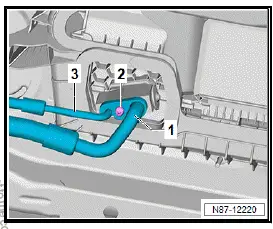
- Remove refrigerant line -1-.
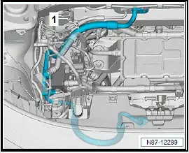
Installing
Installation is carried out in reverse order; note the following:
- ⇒ General information - Air conditioners with refrigerant R134a/R1234yf; Rep. gr. 87 ; Working with the air conditioner service station; Charging refrigerant circuit .
Tightening torques
- ⇒ Rep. gr. 87 ; Assembly overview - refrigerant lines
Removing and installing refrigerant line from condenser to air conditioner compressor [VX81]
Special tools and workshop equipment required
- engine bung set - VAS 6122-
Removing
Immediately seal open lines and connections with clean plugs from engine bung set - VAS 6122- .
- Drain refrigerant circuit ⇒ General information, air conditioning systems with refrigerant R134a/R1234yf; Rep. gr. 87 ; Working with air conditioner service station; Draining refrigerant circuit .
- Remove lock carrier ⇒ General body repairs, exterior; Rep.
gr. 50 ; Lock carrier; Removing and installing lock carrier .
- Remove air intake box of heater and air conditioning unit ⇒ Rep. gr. 87 ; Removing and installing air intake unit of heater and air conditioning unit .
CAUTION
Risk of frostbite from escaping pressurised refrigerant Risk of frostbite on skin and other parts of the body
- Put on protective gloves.
- Put on safety goggles.
- Extract/drain refrigerant and then immediately open up refrigerant circuit.
- Extract/drain refrigerant again if more than 10 minutes have passed since initial extraction and refrigerant circuit has not been opened up. Renewed evaporation has created pressure in the refrigerant circuit.
- Unscrew bolts -2- and -3-.
- Pull off and remove refrigerant line -1-.
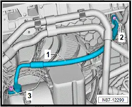
Installing
Install in reverse order of removal, observing the following:
- ⇒ General information, air conditioning systems with refrigerant R134a/R1234yf; Rep. gr. 87 ; Working with air conditioner service station; Charging refrigerant circuit .
Tightening torques
- ⇒ Rep. gr. 87 ; Assembly overview - condenser
- ⇒ Rep. gr. 87 ; Assembly overview - refrigerant lines
Removing and installing refrigerant line from heat exchanger for high-voltage battery to high-pressure line
Special tools and workshop equipment required
- engine bung set - VAS 6122-
Removing
Immediately seal open lines and connections with clean plugs from engine bung set - VAS 6122- .
- ⇒ General information, air conditioning systems with refrigerant R134a/R1234yf; Rep. gr. 87 ; Working with air conditioner service station; Draining refrigerant circuit .
- Remove air intake box of heater and air conditioning unit ⇒ Rep. gr. 87 ; Removing and installing air intake unit of heater and air conditioning unit
CAUTION
Risk of frostbite from escaping pressurised refrigerant Risk of frostbite on skin and other parts of the body
- Put on protective gloves.
- Put on safety goggles.
- Extract/drain refrigerant and then immediately open up refrigerant circuit.
- Extract/drain refrigerant again if more than 10 minutes have passed since initial extraction and refrigerant circuit has not been opened up. Renewed evaporation has created pressure in the refrigerant circuit.
- Unscrew bolts -2-.
- Pull off and remove refrigerant line -1-.
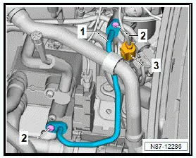
Installing
Install in reverse order of removal, observing the following:
- Make sure that refrigerant lines are properly seated, and tighten them.
- ⇒ General information, air conditioning systems with refrigerant R134a/R1234yf; Rep. gr. 87 ; Working with air conditioner service station; Charging refrigerant circuit .
Tightening torques
- ⇒ Rep. gr. 87 ; Assembly overview - refrigerant lines
Removing and installing refrigerant line from heat exchanger for high-voltage battery to low-pressure line
Special tools and workshop equipment required
- engine bung set - VAS 6122
Removing
Immediately seal open lines and connections with clean plugs from engine bung set - VAS 6122- .
- ⇒ General information, air conditioning systems with refrigerant R134a/R1234yf; Rep. gr. 87 ; Working with air conditioner service station; Draining refrigerant circuit .
- Remove air intake box of heater and air conditioning unit ⇒ Rep. gr. 87 ; Removing and installing air intake unit of heater and air conditioning unit .
CAUTION
Risk of frostbite from escaping pressurised refrigerant Risk of frostbite on skin and other parts of the body
- Put on protective gloves.
- Put on safety goggles.
- Extract/drain refrigerant and then immediately open up refrigerant circuit.
- Extract/drain refrigerant again if more than 10 minutes have passed since initial extraction and refrigerant circuit has not been opened up. Renewed evaporation has created pressure in the refrigerant circuit.
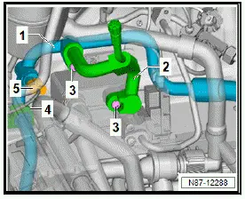
- Unscrew bolts -3-.
- Pull off and remove refrigerant line -2-.
Installing
Install in reverse order of removal, observing the following:
- Make sure that refrigerant lines are properly seated, and tighten them.
- ⇒ General information, air conditioning systems with refrigerant R134a/R1234yf; Rep. gr. 87 ; Working with air conditioner service station; Charging refrigerant circuit .
Tightening torques
- ⇒ Rep. gr. 87 ; Assembly overview - refrigerant lines
Detaching and attaching refrigerant lines at condenser
Special tools and workshop equipment required
- engine bung set - VAS 6122-
Detaching
Immediately seal open lines and connections with clean plugs from engine bung set - VAS 6122- .
- ⇒ General information, air conditioning systems with refrigerant R134a/R1234yf; Rep. gr. 87 ; Working with air conditioner service station; Draining refrigerant circuit .
- Remove lock carrier ⇒ General body repairs, exterior; Rep.
gr. 50 ; Lock carrier; Removing and installing lock carrier .
- Remove front underbody cladding ⇒ General body repairs, exterior; Rep. gr. 66 ; Underbody cladding; Removing and installing front underbody cladding .
CAUTION
Risk of frostbite from escaping pressurised refrigerant Risk of frostbite on skin and other parts of the body
- Put on protective gloves.
- Put on safety goggles.
- Extract/drain refrigerant and then immediately open up refrigerant circuit.
- Extract/drain refrigerant again if more than 10 minutes have passed since initial extraction and refrigerant circuit has not been opened up. Renewed evaporation has created pressure in the refrigerant circuit.
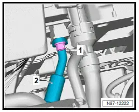
- Unscrew bolt -1-.
- Pull off refrigerant line -2-.
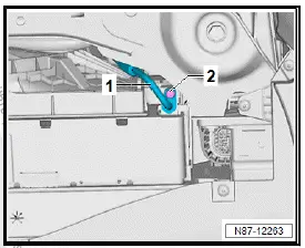
- Unscrew bolt -2-.
- Pull off refrigerant line -1-.
Attaching
Install in reverse order of removal, observing the following:
- ⇒ General information, air conditioning systems with refrigerant R134a/R1234yf; Rep. gr. 87 ; Working with air conditioner service station; Charging refrigerant circuit .
Tightening torques
- ⇒ Rep. gr. 87 ; Assembly overview - condenser
- ⇒ Rep. gr. 87 ; Assembly overview - refrigerant lines
Cleaning refrigerant circuit
Special tools and workshop equipment required
- Adapter - VAS 6338/3-
- Air conditioner service station
- MQB adapter - VAS 6338/38-
- adapter - VAS 6338/12-
- adapter - VAS 6338/48-
- air conditioner service station
- engine bung set - VAS 6122-
- flushing adapter - VAS 6338/80-
- The following procedure is described for an air conditioner service station with integrated flushing device for R1234yf as an example.
- If the refrigerant circuit is contaminated, it is flushed against the normal direction of flow.
- There must be at least 6 kg of refrigerant in the air conditioner service station.
- Observe operating instructions for air conditioner service station ⇒ Operating instructions
Procedure
Seal open lines and connections immediately with clean plugs from engine bung set - VAS 6122- .
- Remove expansion valve and fit MQB adapter - VAS 6338/38- in its place ⇒ Rep. gr. 87 ; Removing and installing expansion valve .
- Remove refrigerant expansion valve 1 - N636- and fit flushing adapter - VAS 6338/80- in its place ⇒ Rep. gr. 87 ; Removing and installing refrigerant expansion valve 1 N636 .
- Detach refrigerant lines from air conditioner compressor ⇒ Rep. gr. 87 ; Detaching and attaching refrigerant lines at air conditioner compressor .
- Screw adapter - VAS 6338/12- with adapter - VAS 6338/48- onto low-pressure refrigerant line.
- Screw adapter - VAS 6338/3- onto high-pressure refrigerant line.
- Remove desiccant bag and re-seal receiver ⇒ Rep. gr. 87 ; Removing and installing desiccant bag .
- Screw caps with seals onto both service connections of refrigerant circuit
Note
The refrigerant circuit cannot be evacuated properly if caps are not fitted, as air will enter when the vacuum in the refrigerant circuit causes the service connection valves to open.
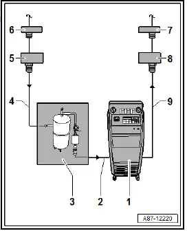
- Connect air conditioner service station -1- to refrigerant circuit for flushing.
- Air conditioner service station
- Refrigerant hose of air conditioner service station, lowpressure side
- Flushing device
- Refrigerant hose
- Adapter - VAS 6338/3-
- Vehicle refrigerant line leading to air conditioner compressor, high-pressure side
- Vehicle refrigerant line leading to air conditioner compressor, low-pressure side
- Adapter - VAS 6338/12- and (if necessary) adapter - VAS 6338/48-
- Refrigerant hose of air conditioner service station, highpressure side
- Start flushing procedure via menu of air conditioner service station ⇒ Operating instructions .
Note
Air conditioner service station displays when flushing procedure has been completed.
CAUTION
Risk of frostbite from escaping pressurised refrigerant Risk of frostbite on skin and other parts of the body
- Put on protective gloves.
- Put on safety goggles.
- Extract/drain refrigerant and then immediately open up refrigerant circuit.
- Extract/drain refrigerant again if more than 10 minutes have passed since initial extraction and refrigerant circuit has not been opened up. Renewed evaporation has created pressure in the refrigerant circuit.
- Check pressure in flushing circuit; only detach refrigerant hoses and adapters if pressure is below or equal to ambient pressure.
- Renew desiccant bag ⇒ Rep. gr. 87 ; Removing and installing desiccant bag .
- Check expansion valve for dirt or corrosion. If necessary, renew expansion valve ⇒ Rep. gr. 87 ; Removing and installing expansion valve .
- Remove rinsing adapters and assemble refrigerant circuit.
- Depending on vehicle version: Adjust quantity of refrigerant oil in refrigerant circuit ⇒ ; Rep. gr. ; Renewing components and ⇒ Rep. gr. 00 ; Refrigerant oil capacities .
- ⇒ General information - Air conditioners with refrigerant R134a/R1234yf; Rep. gr. 87 ; Working with the air conditioner service station; Charging refrigerant circuit .
- After charging refrigerant circuit and re-energising high-voltage system, perform "A/C compressor initial break-in" function with ⇒ Vehicle diagnostic tester ⇒ Rep. gr. 00 ; Starting diagnosis .
Tightening torques
- ⇒ Rep. gr. 87 ; Assembly overview - refrigerant lines
- ⇒ Rep. gr. 87 ; Assembly overview - evaporator housing