Steering column switch module
In this manual: Steering column switch module
2steps
~12min
1/5difficulty
Done 0 of 2
- Assembly overview - steering column switch module
- Removing and installing steering column electronics control unit [J527]
Assembly overview - steering column switch module
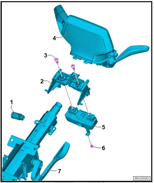
- Starter button - E378-
- ⇒ "3.11 Removing and installing starter button [E378]"
- Bracket for dash panel insert
- Shear bolt
- Qty. 2
- Steering column electronics control unit - J527-
- With driving mode selector, depending on equipment/version
- With wiper switch - EWith intermittent wiper switch - E22- With turn signal switch - E2- With headlight dipper and flasher switch - E4- With electromechanical parking brake button - E538-
- With airbag coil connector and return ring with slip ring - F138- With selector lever locked in position P switch - F319-
- With selector lever position display - Y6-
- Depending on equipment/ version, with cruise control system (CCS) switch - E45- With cruise control system (CCS) SET button - E227- With multifunction display call-up button - E86- Wit heated steering wheel - Z36-
- ⇒ Rep. gr. 94 ; Removing and installing steering column electronics control unit [J527]
- Control unit for electronic steering column lock - J764-
- ⇒ Running gear, axles, steering; Rep. gr. 48 ; Steering column; Removing and installing control unit for electronic steering column lock [J764]
- Bolt
- 2,5 N·m
- Steering column
- ⇒ Running gear, axles, steering; Rep. gr. 48 ; Steering column; Removing and installing steering column
Removing and installing steering column electronics control unit [J527]
Steering column electronics control unit - J527- is referred to hereafter as control unit.
Removing
- Move steering wheel to rearmost and lowest position. Use full range of steering column adjustment for this purpose.
- Remove lower steering column trim ⇒ General body repairs, interior; Rep. gr. 68 ; Compartments/covers; Removing and installing lower steering column trim .
- Remove control unit with display unit for driver information system - J1254- ⇒ Rep. gr. 90 ; Removing and installing control unit with display unit for driver information system [J1254] .
NOTICE
Risk of damage to the electronic components due to electrostatic discharge.
- Discharge any static charge by briefly touching the door striker plate.
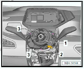
- Disconnect electrical connector -2-.
- Unscrew bolts -3-.
NOTICE
Risk of damage to the return ring.
- When removed, the return ring with slip ring must not be turned.
- Pull off control unit -1-.
Installing
Install in the reverse order of removal, observing the following:
Before pushing on control unit -3-, ensure the following:
- "Arrows" -4- must align.
- Coil connector -2- must be visible in window -1-.

Was this page helpful?