Coolant pump/coolant regulation
- Assembly overview - electric coolant pump
- Assembly overview - coolant valves
- Exploded view - coolant temperature senders
- Removing and installing coolant pump for high-voltage battery [V590], rear-wheel drive
- Removing and installing coolant pump for high-voltage battery [V590], all-wheel drive
- Removing and installing coolant pump for low-temperature circuit [V468]
- Removing and installing mixing valve for high-voltage battery pre-heating, rear-wheel drive
- Removing and installing mixing valve for high-voltage battery pre-heating, all-wheel drive
- Removing and installing mixing valve 2 for high-voltage battery [V696] pre-heating, heat pump
- Removing and installing temperature sensor [G18]
- Removing and installing coolant temperature sender 1 for high-voltage battery G898
- Removing and installing coolant temperature sender 2 for high-voltage battery G899
Assembly overview - electric coolant pump
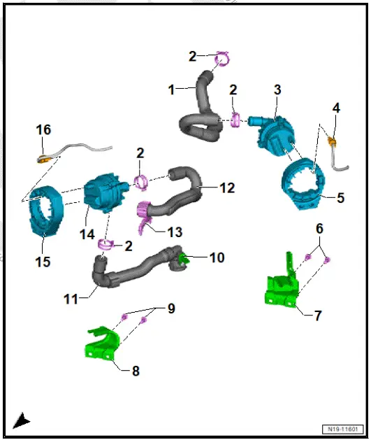
- Coolant hose
- Clip
- Coolant pump for low-temperature circuit - V468-
- ⇒ Rep. gr. 19 ; Removing and installing coolant pump for low-temperature circuit [V468]
- Electrical connector
- Rubber mounting
- Bolt
- Qty. 2
- 8 N·m
- Bracket
- Bracket
- Bolt
- Qty. 2
- 8 N·m
- Coolant temperature sender 2 for high-voltage battery - G899-
- ⇒ Rep. gr. 19 ; Removing and installing coolant temperature sender 2 for highvoltage battery [G899]
- Coolant hose
- Coolant hose
- Clip
- Coolant pump for high-voltage battery - V590-
- ⇒ Rep. gr. 19 ; Removing and installing coolant pump for high-voltage battery [V590]
- Rubber mounting
- Electrical connector
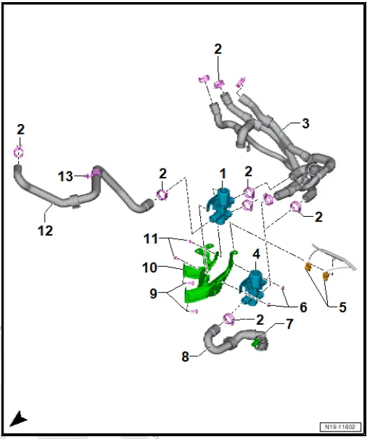
Assembly overview - coolant valves
- Mixing valve 2 for highvoltage battery pre-heating - V696-
- Depending on equipment/ installation period
- ⇒ Rep. gr. 19 ; Removing and installing mixing valve 2 for high-voltage battery pre-heating [V696]
- Clip
- Coolant hose
- Mixing valve for highvoltage battery pre-heating - V683-
- ⇒ Rep. gr. 19 ; Removing and installing mixing valve for high-voltage battery pre-heating [V683]
- Electrical connector
- Nut
- Qty. 2
- 8 N·m
- Coolant temperature sender 1 for high-voltage battery - G898-
- ⇒ Rep. gr. 19 ; Removing and installing coolant temperature sender 1 for highvoltage battery [G898]
- Coolant hose
- Bolt
- Qty. 2
- 8 N·m
- Bracket
- Bolt
- Qty. 2
- 8 N·m
- Coolant hose
- Clip
Exploded view - coolant temperature senders
Exploded view - bolted coolant temperature sender
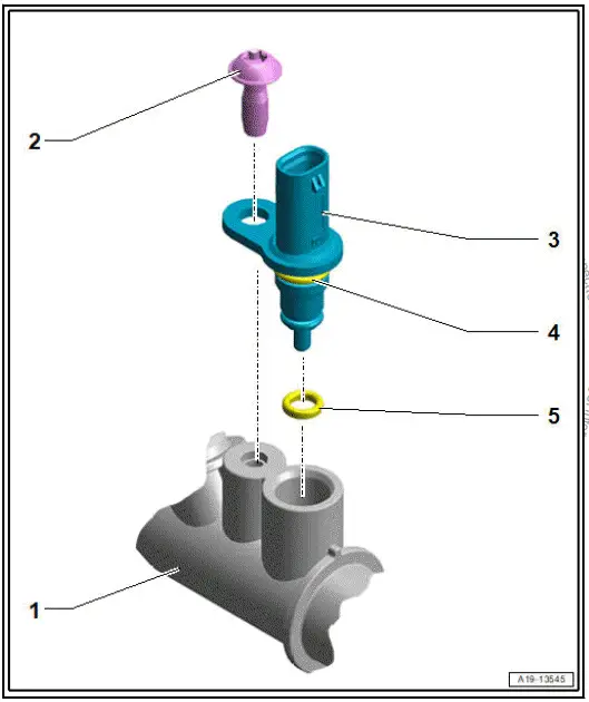
- Connection
- Bolt
- 8 N·m
- Coolant temperature sender
- Coolant temperature sender 1 for high-voltage battery - G898- in coolant supply
- Coolant temperature sender 2 for high-voltage battery - G899- in coolant return
- ⇒ Rep. gr. 19 ; Removing and installing coolant temperature sender 1 for highvoltage battery G898
- ⇒ Rep. gr. 19 ; Removing and installing coolant temperature sender 2 for highvoltage battery G899
- Support ring
- O-ring
- Renew after removing
Exploded view - inserted coolant temperature sender
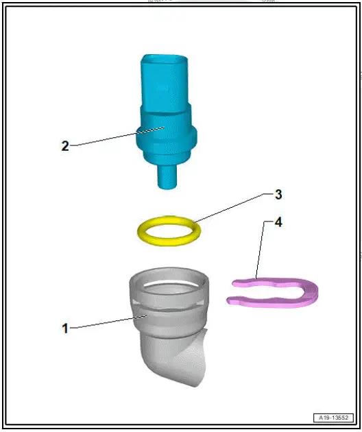
- Connection
- Temperature sensor - G18-
- ⇒ Rep. gr. 19 ; Removing and installing temperature sensor G18
- O-ring
- Renew after removing
- Retaining clip
Removing and installing coolant pump for high-voltage battery [V590], rear-wheel drive
Special tools and workshop equipment required
- hose clamps, up to 25 mm - 3094-
Coolant pump for high-voltage battery - V590- will henceforth be referred to as "coolant pump".
Removing
- Remove front underbody cladding ⇒ General body repairs, exterior; Rep. gr. 66 ; Underbody cladding; Removing and installing front underbody cladding .
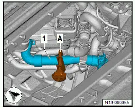
- Unscrew bolts -1-.
- Open clip -2-.

- Clamp off coolant hoses before and after coolant pump using hose clamps, up to 25 mm - 3094- -A-.
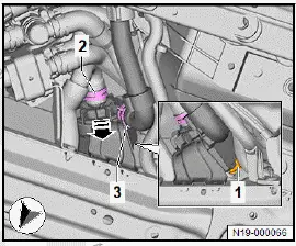
- Pull coolant pump in direction of -arrow-, and disconnect electrical connector -1-.
- Open clamps -2- and -3-, and pull off coolant hoses.
Installing
Install in reverse order of removal, observing the following:
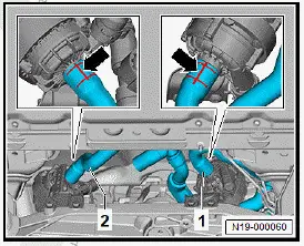
- Fit coolant hoses, and make sure that installation markings are properly aligned.
Important
- Installation markings -arrows- on coolant hoses -1- and -2- must face vertically upwards.
- ⇒ Rep. gr. 19 ; Fill cooling system .
Tightening torques
- ⇒ Rep. gr. 19 ; Assembly overview - electric coolant pump
Removing and installing coolant pump for high-voltage battery [V590], all-wheel drive
Removing
Coolant pump for high-voltage battery - V590- will henceforth be referred to as "coolant pump".
Vehicles without heat pump:
- Remove mixing valve for high-voltage battery pre-heating - V683- and bracket ⇒ Rep. gr. 19 ; Removing and installing mixing valve for high-voltage battery pre-heating [V683] .
All vehicles (continued)
Vehicles with heat pump:
- Remove bracket for mixing valve 2 for high-voltage battery pre-heating - V696- ⇒ Rep. gr. 19 ; Removing and installing mixing valve 2 for high-voltage battery pre-heating [V696] .
All vehicles (continued)
- Disconnect electrical connector -1-.
- Pull out securing clip -arrow-, and pull off plug-in connector -2-.

- Pull coolant pump downwards slightly -arrow-, and disconnect electrical connector -1-.
- Open hose clip -2-, and pull off coolant hose.

Installing
Install in reverse order of removal, observing the following:
- Fit coolant hoses, and make sure that installation markings are properly aligned.
Important
- Installation markings -arrows- on coolant hoses -1- and -2- must face vertically upwards.
- ⇒ Rep. gr. 19 ; Fill cooling system .
Tightening torques
- ⇒ Rep. gr. 19 ; Assembly overview - electric coolant pump
Removing and installing coolant pump for low-temperature circuit [V468]
Coolant pump for low-temperature circuit - V468- will henceforth be referred to as "coolant pump".
Removing
- Remove front underbody cladding ⇒ General body repairs, exterior; Rep. gr. 66 ; Underbody cladding; Removing and installing front underbody cladding .
- ⇒ Rep. gr. 19 ; Drain coolant .
- Unscrew bolts -1-.
- Pull electrical wires -arrow- off bracket.
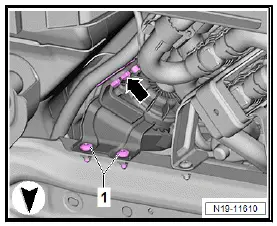
- Pull coolant pump in direction of -arrow-, and disconnect electrical connector -1-.
- Loosen clips -2- and pull off coolant hoses.
Installing
Install in reverse order of removal, observing the following:
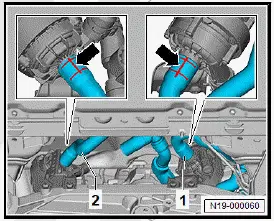
- Fit coolant hoses, and make sure that installation markings are properly aligned.
Important
- Installation markings -arrows- on coolant hoses -1- and -2- must face vertically upwards.
- ⇒ Rep. gr. 19 ; Fill cooling system .
Tightening torques
- ⇒ Rep. gr. 19 ; Assembly overview - electric coolant pump
Removing and installing mixing valve for high-voltage battery pre-heating, rear-wheel drive
The mixing valve for high-voltage battery pre-heating - V683- will henceforth be referred to as "mixing valve".
Removing
- Remove front underbody cladding ⇒ General body repairs, exterior; Rep. gr. 66 ; Underbody cladding; Removing and installing front underbody cladding .
- ⇒ Rep. gr. 19 ; Drain coolant .
- Remove cable holder -arrow-.
- Unscrew bolts -1-.
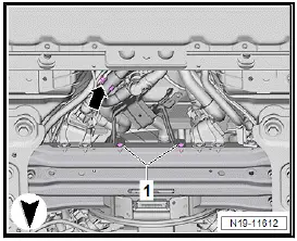
- Disconnect electrical connector -1-.
- Pull out retaining clip -arrow-, and pull plug-in connector -2- off high-voltage battery 1 - AX2- .

- Pull mixing valve in direction of -arrow-, and disconnect electrical connector -1-.
- Unclip electrical wire -2- from retainer -3-.
- Loosen clamps -4-, and pull off coolant hoses.
- Remove mixing valve with bracket -3-.

- Unscrew nuts -arrows-.
- Loosen clamp -1-, and pull coolant hose off mixing valve -2-.

Installing
Install in reverse order of removal, observing the following:
- Observe installation markings on mixing valve and coolant hoses.
- ⇒ Rep. gr. 19 ; Fill cooling system .
Tightening torques
- ⇒ Rep. gr. 19 ; Assembly overview - coolant valves
Removing and installing mixing valve for high-voltage battery pre-heating, all-wheel drive
Removing
The mixing valve for high-voltage battery pre-heating - V683- will henceforth be referred to as "mixing valve".
- Remove front underbody cladding ⇒ General body repairs, exterior; Rep. gr. 66 ; Underbody cladding; Removing and installing front underbody cladding .
- ⇒ Rep. gr. 19 ; Drain coolant .
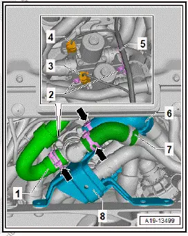
- Disconnect electrical connector -1-.
- Pull out securing clip -arrow-, and pull off plug-in connector -2-.
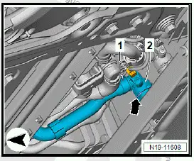
- Detach cable holder -1-.
- Open hose retainer -2-, and move aside coolant hose -3-.
- Unscrew bolts -arrows-.
- Push coolant pump bracket -4- upwards.

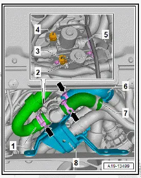
- Pull off electrical connector -1-.
- Pull out securing clip -arrow-, and pull off plug-in connector -2-.
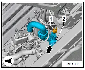
- Open hose clips -arrows-, and pull off coolant hoses -1-, -6- and -7-.
- Pull mixing valve holder -8- downwards, and disconnect electrical connector -3-.
- Unclip electrical wire -5- from holder.
- Unscrew nuts -2-, and remove mixing valve.
Installing
Install in reverse order of removal, observing the following:
- Observe installation markings on mixing valve and coolant hoses.
- ⇒ Rep. gr. 19 ; Fill cooling system .
Tightening torques
- ⇒ Rep. gr. 19 ; Assembly overview - coolant valves
- ⇒ General body repairs, exterior; Rep. gr. 66 ; Underbody cladding; Assembly overview - underbody cladding
Removing and installing mixing valve 2 for high-voltage battery [V696] pre-heating, heat pump
Removing and installing mixing valve 2 for high-voltage battery pre-heating V696
Mixing valve 2 for high-voltage battery pre-heating - V696- is referred to as mixing valve below.
Removing
- Remove mixing valve for high-voltage battery pre-heating - V683- ⇒ Rep. gr. 19 ; Removing and installing mixing valve for high-voltage battery pre-heating V683 .
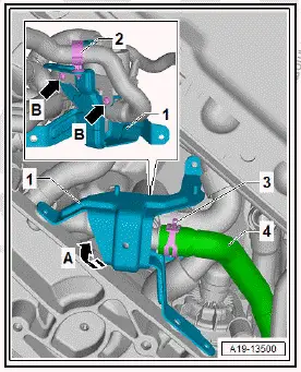
- Pull bracket -8- downwards and unplug electrical connector -4-.
- Unfasten clip -3- and detach coolant hose -4-.
- Swivel bracket -1- in direction of -arrow A-, release retaining clip -2- and move coolant hose clear.
- Remove bolts -arrows B- and detach bracket -1-.
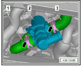
- Release clips -arrows- and detach coolant hoses -1- and -3-.
Installing
Installation is carried out in reverse order; note the following:
- Note installation markings on mixing valve and coolant hoses.
- ⇒ Rep. gr. 19 ; Fill cooling system .
Tightening torques
- ⇒ Rep. gr. 19 ; Assembly overview - coolant valves
Removing and installing temperature sensor [G18]
Removing
- ⇒ Rep. gr. 19 ; Draining coolant
- Remove rear right wheel ⇒ Running gear, axles, steering; Rep. gr. 44 ; Wheels, tyres; Removing wheel .
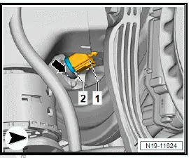
- Disconnect connector -1-.
- Pull out retaining clip -arrow-, and remove temperature sensor - G18- -2-.
Installing
Install in reverse order of removal, observing the following:
- Renew O-ring for temperature sensor.
- ⇒ Rep. gr. 19 ; Fill cooling system .
Tightening torques
- ⇒ Running gear, axles, steering; Rep. gr. 44 ; Wheels, tyres; Specified torques for wheel bolts
Removing and installing temperature sensor [G18]
Special tools and workshop equipment required
- hose clamps up to 25mm - 3094-
Removing
- Remove rear centre underbody cladding ⇒ General body repairs, exterior; Rep. gr. 66 ; Underbody cladding; Removing and installing rear centre underbody cladding .
- Remove rear underbody cladding ⇒ General body repairs, exterior; Rep. gr. 66 ; Underbody cladding; Removing and installing rear underbody cladding .
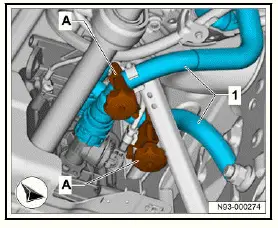
- Clamp off coolant hoses -1- using hose clamps up to 25mm - 3094- -A-.
- Disconnect electrical connector -1-.
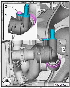
- Open retaining clip -2- and -3-, and pull coolant hoses off charging unit.

- Pull coolant hose -3- downwards.
- Unscrew bolt -2-, and pull out temperature sensor - G18- .
Installing
Install in reverse order of removal, observing the following:
- Insert temperature sensor - G18- , and tighten bolt.
- ⇒ Rep. gr. 19 ; Filling cooling system
Tightening torques
- ⇒ Rep. gr. 19 ; Assembly overview - coolant temperature sender
Removing and installing coolant temperature sender 1 for high-voltage battery G898
Coolant temperature sender 1 for high-voltage battery - G898- is referred to as coolant temperature sender below.
Removing
CAUTION
The cooling system may be under pressure. Risk of scalding due to hot steam and hot coolant Danger of scalding skin and other parts of the body
- Put on protective gloves.
- Put on safety goggles.
- Cover filler cap on expansion tank with a suitable cloth and open carefully to release pressure.
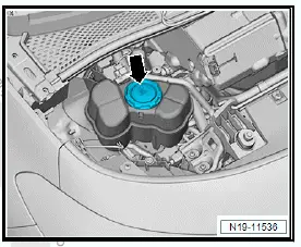
- Open filler cap on coolant expansion tank -arrow- briefly to release pressure in cooling system and then tighten cap again.

- Remove underbody trim (front) ⇒ General body repairs, exterior; Rep. gr. 66 ; Underbody trim; Removing and installing underbody trim (front) .
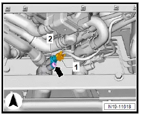
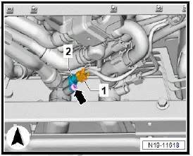
- Unplug electrical connector -1-.
- Remove bolt -arrow-.
- Pull coolant temperature sender -2- out and insert new coolant temperature sender -2- immediately.
Installing
- Tighten bolt -arrow-.
- Plug in electrical connector -1-.
- Install underbody trim (front) ⇒ General body repairs, exterior; Rep. gr. 66 ; Underbody trim; Removing and installing underbody trim (front) .
- Fill up coolant and check filling quality ⇒ Rep. gr. 19 ; Checking filling quality .
Tightening torques
- ⇒ Rep. gr. 19 ; Exploded view - coolant temperature senders
- ⇒ General body repairs, exterior; Rep. gr. 66 ; Underbody trim; Exploded view - underbody trim
Removing and installing coolant temperature sender 2 for high-voltage battery G899
Coolant temperature sender 2 for high-voltage battery - G899- is referred to as coolant temperature sender below.
Removing
CAUTION
The cooling system may be under pressure. Risk of scalding due to hot steam and hot coolant Danger of scalding skin and other parts of the body
- Put on protective gloves.
- Put on safety goggles.
- Cover filler cap on expansion tank with a suitable cloth and open carefully to release pressure
- Open filler cap on coolant expansion tank -arrow- briefly to release pressure in cooling system and then tighten cap again.
- Remove underbody trim (front) ⇒ General body repairs, exterior; Rep. gr. 66 ; Underbody trim; Removing and installing underbody trim (front) .

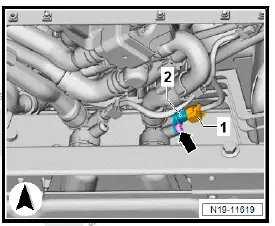
- Unplug electrical connector -1-.
- Remove bolt -arrow-.
- Pull coolant temperature sender -2- out and insert new coolant temperature sender -2- immediately.
Installing
- Tighten bolt -arrow-.
- Plug in electrical connector -1-.
- Install underbody trim (front) ⇒ General body repairs, exterior; Rep. gr. 66 ; Underbody trim; Removing and installing underbody trim (front) .
- Fill up coolant and check filling quality ⇒ Rep. gr. 19 ; Checking filling quality .
Tightening torques
- ⇒ Rep. gr. 19 ; Exploded view - coolant temperature senders
- ⇒ General body repairs, exterior; Rep. gr. 66 ; Underbody trim; Exploded view - underbody trim