Steering rack
- Assembly overview - steering rack, left-hand drive
- Assembly overview - steering rack, right-hand drive
- Assembly overview - track rods
- Removing and installing steering rack, all-wheel drive
- Removing and installing steering rack, rear-wheel drive
- Servicing steering rack
- Removing and installing boot
- Removing and installing track rod
- Removing and installing track rod ball joint
Assembly overview - steering rack, left-hand drive
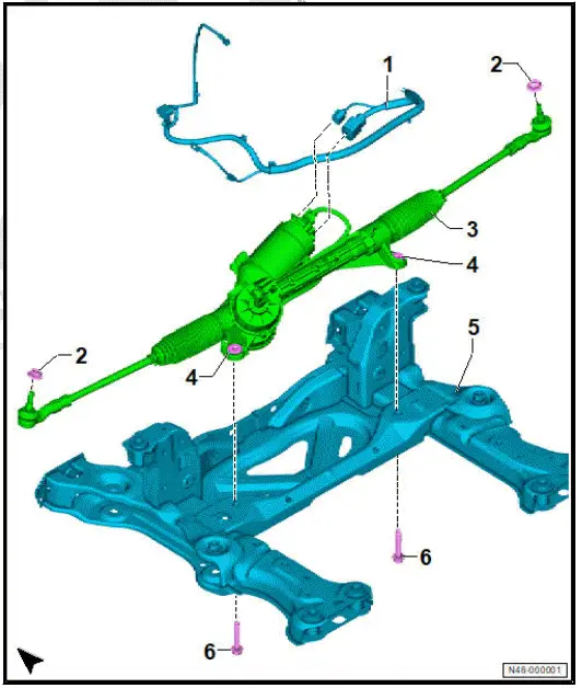
- Electrical wire
- Nut
- Qty. 2
- Renew after removing
- M 12 x 1.5
- 20 N·m +90º
- Steering rack with power steering control unit - J500-
- ⇒ Rep. gr. 48 ; Assembly overview - track rods
- ⇒ Rep. gr. 48 ; Removing and installing steering rack
- Threaded bush
- Qty. 2
- ⇒ Rep. gr. 48 ; Repairing steering rack
- Subframe
- ⇒ Rep. gr. 40 ; Assembly overview - subframe
- ⇒ Rep. gr. 40 ; Fixing subframe in position
- ⇒ Rep. gr. 40 ; Removing and installing subframe with steering rack
- Bolt
- Qty. 2
- Renew after removing
- M12 × 1.5 × 70
- 70 N·m +180º
Assembly overview - steering rack, right-hand drive

- Electrical wire
- Nut
- Qty. 2
- Renew after removing
- 20 N·m +90º
- Steering rack with power steering control unit - J500-
- ⇒ Rep. gr. 48 ; Assembly overview - track rods
- ⇒ Rep. gr. 48 ; Removing and installing steering rack
- Threaded bush
- Qty. 2
- ⇒ Rep. gr. 48 ; Repairing steering rack
- Subframe
- ⇒ Rep. gr. 40 ; Assembly overview - subframe
- ⇒ Rep. gr. 40 ; Fixing subframe in position
- ⇒ Rep. gr. 40 ; Removing and installing subframe with steering rack
- Bolt
- Qty. 2
- Renew after removing
- M12 × 1.5 × 70
- 70 N·m +180º
Assembly overview - track rods
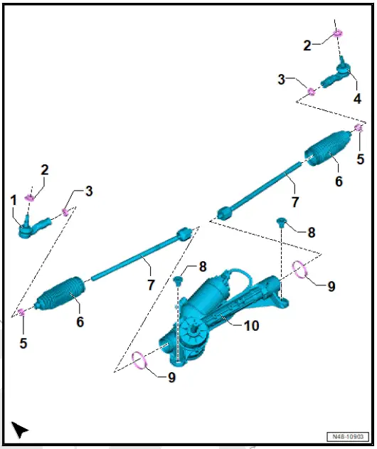
- Left track rod ball joint
- ⇒ Rep. gr. 48 ; Removing and installing track rod ball joint
- Nut
- Qty. 2
- Renew after removing
- M 12 x 1.5
- 20 N·m +90º
- Nut
- Qty. 2
- M16 × 1.5
- 70 N·m
- Right track rod ball joint
- ⇒ Rep. gr. 48 ; Removing and installing track rod ball joint
- Clamp
- Qty. 2
- Renew after removing
- Boot
- Renew after removing
- ⇒ Rep. gr. 48 ; Removing and installing boot
- Track rod
- ⇒ Rep. gr. 48 ; Removing and installing track rod
- 100 N·m
- Threaded bush
- Qty. 2
- ⇒ Rep. gr. 48 ; Servicing steering rack
- Clamp
- Qty. 2
- Renew after removing
- Steering rack with power steering control unit - J500-
- ⇒ Rep. gr. 48 ; Assembly overview - steering rack
- ⇒ Rep. gr. 48 ; Removing and installing steering rack
Removing and installing steering rack, all-wheel drive
Removing
Steering rack with power steering control unit - J500- will henceforth be referred to as "steering rack".
- Turn steering wheel to straight ahead position.
- Disconnect battery ⇒ Electrical system; Rep. gr. 27 ; Battery; Disconnecting and connecting battery .
- Remove front underbody cladding ⇒ General body repairs, exterior; Rep. gr. 66 ; Underbody cladding; Removing and installing front underbody cladding .
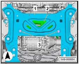
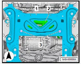
- Loosen bolts -3-.
- ⇒ Rep. gr. 10 ; Removing and installing front motor; Removing front motor
- Lever steering rack -2- with threaded bushes out of holes of subframe -1-.
- Unscrew bolts -3-.
- Remove steering rack.
Installing
Install in reverse order of removal, observing the following:
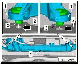
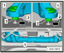
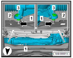
- Position steering rack -1- on subframe -2-.
Important
- Threaded bushes -3- of steering rack -1- must be inserted in holes -arrows- of subframe -2-.
- Perform basic setting for steering angle sender using ⇒ Vehicle diagnostic tester ⇒ Rep. gr. 00 ; Access to diagnoses .
- Adapt electromechanical power steering using ⇒ Vehicle diagnostic tester ⇒ Rep. gr. 00 ; Access to diagnoses .
Important
- If a new steering rack has been installed:
Tightening torques
- ⇒ Rep. gr. 48 ; Assembly overview - steering rack
Removing and installing steering rack, rear-wheel drive
Removing and installing steering rack, left-hand drive
Removing
Steering rack with power steering control unit - J500- will henceforth be referred to as "steering rack".
- Turn steering wheel to straight ahead position.
- Disconnect battery ⇒ Electrical system; Rep. gr. 27 ; Battery; Disconnecting and connecting battery .
- Remove front underbody cladding ⇒ General body repairs, exterior; Rep. gr. 66 ; Underbody cladding; Removing and installing front underbody cladding .
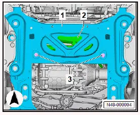
- Unscrew bolts -3-.
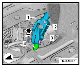
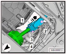
- Unscrew bolt -3-.
- Pull universal joint -1- in direction of -arrow- off steering rack -4-.
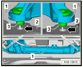
- Remove track rods on both sides of vehicle ⇒ Rep. gr. 48 ; Removing and installing track rod .
- Lever steering rack -1- with threaded bushes -3- out of holes -arrows- of subframe -2-.
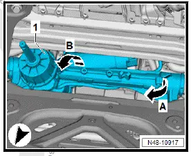
- First, swing steering rack -1- on right side in direction of -arrow A-.
- Then, swing steering rack -1- in direction of -arrow B-.
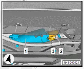
- Disconnect electrical connectors -1- and -4- from steering rack -3-.
- Unclip electrical wire from steering rack.
- Remove steering rack -3- downwards.
Installing
Install in reverse order of removal, observing the following:
- Position steering rack -1- on subframe -2-.
Important
- Threaded bushes -3- of steering rack -1- must be inserted in holes -arrows- of subframe -2-.
- Perform basic setting for steering angle sender using ⇒ Vehicle diagnostic tester ⇒ Rep. gr. 00 ; Access to diagnoses .
- Adapt electromechanical power steering using ⇒ Vehicle diagnostic tester ⇒ Rep. gr. 00 ; Access to diagnoses .
Important
- If a new steering rack has been installed:
Tightening torques
- ⇒ Rep. gr. 48 ; Assembly overview - steering rack
Removing and installing steering rack, right-hand drive vehicle
Removing
Steering rack with power steering control unit - J500- will henceforth be referred to as "steering rack".
- Turn steering wheel to straight ahead position.
- Disconnect battery ⇒ Electrical system; Rep. gr. 27 ; Battery; Disconnecting and connecting battery .
- Remove front underbody cladding ⇒ General body repairs, exterior; Rep. gr. 66 ; Underbody cladding; Removing and installing front underbody cladding .
- Unscrew bolts -3-.
- Unscrew bolt -3-.
- Pull universal joint -1- in direction of -arrow- off steering rack -4-.
- Remove track rods on both sides of vehicle ⇒ Rep. gr. 48 ; Removing and installing track rod .
- Disconnect electrical connectors -2- and -3- from steering rack -1-.
- Unclip electrical wire from steering rack.
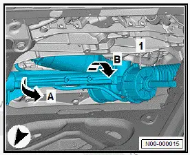
- Lever steering rack -1- with threaded bushes -3- out of holes -arrows- of subframe -2-.
- Swing steering rack -1- on left side in direction of -arrow A-.
- Swing steering rack -1- in direction of -arrow B-.
- Remove steering rack -1- downwards.
Installing
Install in reverse order of removal, observing the following:

- Position steering rack -1- on subframe -2-.
Important
- Threaded bushes -3- of steering rack -1- must be inserted in holes -arrows- of subframe -2-.
- Perform basic setting for steering angle sender using ⇒ Vehicle diagnostic tester ⇒ Rep. gr. 00 ; Access to diagnoses .
- Adapt electromechanical power steering using ⇒ Vehicle diagnostic tester ⇒ Rep. gr. 00 ; Access to diagnoses .
Important
- If a new steering rack has been installed:
Tightening torques
- ⇒ Rep. gr. 48 ; Assembly overview - steering rack
Servicing steering rack
Removing
Power steering control unit - J500- is fitted in steering rack.
Steering rack and power steering control unit - J500- are referred to as steering rack below.
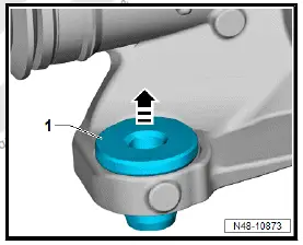
- Remove steering rack ⇒ Rep. gr. 48 ; Removing and installing steering rack .
- Drive out threaded bush -1- in direction of -arrow- using a hammer.
Installing
Installation is carried out in reverse order; note the following:
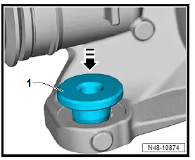
- Fit threaded bush -1-, making sure it is straight.
- Drive in threaded bush -1- as far as it will go from above using a hammer.
Tightening torques
- ⇒ Rep. gr. 40 ; Exploded view - subframe
- ⇒ Rep. gr. 48 ; Exploded view - steering rack
- ⇒ General body repairs, exterior; Rep. gr. 66 ; Underbody trim; Exploded view - underbody trim
Removing and installing boot
Special tools and workshop equipment required
- pinch-on clamp tool for steering rack - VAS 6199A
Removal and installation are described for the left side of vehicle as an example.
Removing
- Remove wheel ⇒ Rep. gr. 44 ; Removing and installing wheel .
- Clean steering rack and track rod on outer side in area of boot using a cleaning cloth.
- Remove track rod ball joint ⇒ Rep. gr. 48 ; Removing and installing track rod ball joint .
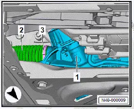
- Open clamp -3- for boot -2- on steering rack -1-.
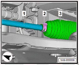
- Open clamp -2- of boot -3- on track rod -1-.
- Pull off boot -3-.
Installing
Install in reverse order of removal, observing the following:
NOTICE
Check the steering rack for signs of wear.
- The steering rack must be renewed if it shows signs of corrosion, damage, wear or soiling.
- If there is no film of grease on the steering rack, the steering rack must be renewed.
- Do not grease rack.
- Push new clamps and boot onto track rod.
- Lightly grease sealing surface between boot and track rod/ steering rack. For allocation, see ⇒ Electronic parts catalogue (ETKA) .
- Push boot onto steering rack to stop.
- Secure new clamp -1- on boot using pinch-on clamp tool for steering rack - VAS 6199A- .
- Clamp together clamp -1- until it is properly deformed -arrow-.

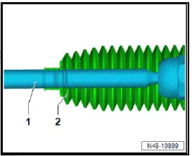
- Position boot -2- in installation position on outside of track rod -1-.
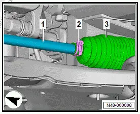
- Secure clamp -2- of boot -3- on track rod -1-.
- Carry out wheel alignment ⇒ Rep. gr. 44 ; Wheel alignment .
Tightening torques
- ⇒ Rep. gr. 48 ; Assembly overview - track rods
Removing and installing track rod
Special tools and workshop equipment required
- open-end spanner insert - V.A.G 1923-
Removing
Removal and installation are described for the left side of vehicle as an example.
- Remove wheel ⇒ Rep. gr. 44 ; Removing and installing wheel .
- Clean steering rack and track rod on outer side in area of boot using a cleaning cloth.
- Remove track rod ball joint ⇒ Rep. gr. 48 ; Removing and installing track rod ball joint .
- Open clamp -3- for boot -2- on steering rack -1-.
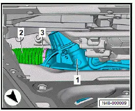
- Pull boot off steering rack -2-, and push it outwards -arrow-.
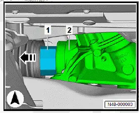
- Unscrew track rod -1- using open-end spanner insert - V.A.G 1923- .
Installing
Install in reverse order of removal, observing the following:
NOTICE
Check the steering rack for signs of wear.
- The steering rack must be renewed if it shows signs of corrosion, damage, wear or soiling.
- If there is no film of grease on the steering rack, the steering rack must be renewed.
- Do not grease rack.
- Screw in and tighten track rod.
- Slightly grease sealing surface between boot and steering rack. Allocation ⇒ Electronic parts catalogue (ETKA) .
- Install boot ⇒ Rep. gr. 48 ; Removing and installing boot .
- Carry out wheel alignment ⇒ Rep. gr. 44 ; Wheel alignment .
Tightening torques
- ⇒ Rep. gr. 48 ; Assembly overview - track rods
Removing and installing track rod ball joint
Special tools and workshop equipment required
- ball joint puller - 3287ARemoving
Removal and installation are described for the left side of vehicle as an example.
- Remove wheel ⇒ Rep. gr. 44 ; Removing and installing wheel .
- Turn steering wheel to full left lock.
- Turn steering as follows:
Important
- For left track rod ball joint, turn steering to full left lock.
- For right track rod ball joint, turn steering to full right lock.
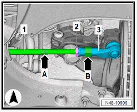
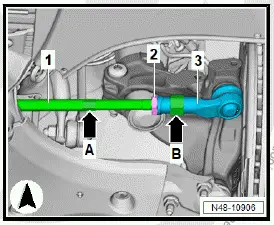
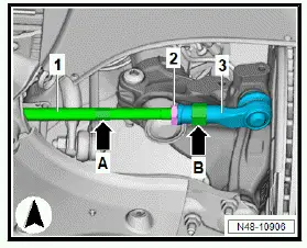
- Mark or measure installation position of track rod ball joint -3- on track rod -1-.
- Loosen nut -2- by counterholding at hexagon -arrow A- on track rod -1-.
- Loosen track rod -1- at track rod ball joint -3-. Use suitable tool on hexagon -arrow A- and -arrow B- to do this.
- Loosen nut -2- on track rod ball joint -4-, but do not unscrew it completely.
- Counterhold on pin using a suitable tool while doing so.
- Unscrew nut -2- only up to end of thread.
NOTICE
Risk of damage to wheel bearing housing! Loosened bushes on wheel bearing housing due to incorrect placement of ball joint puller.
- Position ball joint puller in such a way that fulcrum of bottom support is on bush and not on wheel bearing housing.
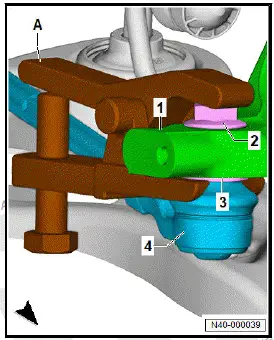
- Use ball joint puller - 3287A- -A- to press track rod ball joint -4- off wheel bearing housing -1-. Unscrew nut -2-.
- Unscrew track rod ball joint -3- from track rod -1-.
- Use suitable tool on hexagon -arrow A- and -arrow B- to do this.
Installing
Install in reverse order of removal, observing the following:
- Screw track rod ball joint -3- onto track rod -1- up to previously applied mark, and secure it with nut -2-.
- Carry out wheel alignment ⇒ Rep. gr. 44 ; Wheel alignment .
Tightening torques
- ⇒ Rep. gr. 48 ; Assembly overview - steering rack
- ⇒ Rep. gr. 48 ; Assembly overview - track rods