Resistance spot welding

In this manual: Resistance spot welding
Basic information on body repairs — 1Explanation of symbols — 1Overview of materials used — 1Joining and separating techniques — 1Surface repair — 1Corrosion protection — 1Noise insulation — 1Plastic repair — 1General notes - windows — 1Self-adhesive components — 1Noises — 1Resistance spot welding — 1Solid rivet — 1Pop rivet — 1Incorrect riveting — 1Overview of riveting attachments — 1Making a flow-drill screw connection, pre-drilled hole in upper part — 1Distinction of types of plastic — 1Processing instructions - original products — 1Preparing plastic repair — 1Repairing deformations — 1Bonding plastic attachments — 1Welding plastic attachments — 1Glass repair- Introduction — 1Carrying out glass repair — 1General notes on the use of adhesives — 1Preparing old undamaged windows for installing — 1Preparing new windows for installation — 1Installation instructions for bonded windows — 1Bonding log — 1Preparing gas strut for disposal — 1Preparing rear lid drive unit VX69/rear lid drive unit 2 VX77 for disposal — 1Causes of water ingress — 1Locating water ingress — 1Interior equipment — 1Compartments/covers — 1Equipment — 1Centre console — 1Front centre armrest — 1Interior mirror — 1Passenger protection — 1Seat belts — 1Child seat anchors — 1Airbag system — 1Airbag control unit — 1Front airbag, driver side — 1Front passenger airbag — 1Side airbags — 1Curtain airbags — 1Airbag crash sensors — 1Seat belt verification — 1Seat occupied recognition — 1Trim, insulation — 1Front door trims — 1Rear door trims — 1Dash panel — 1Central tube for dash panel — 1Interior trims — 1Luggage compartment trims — 1Roof trims — 1Seat frames — 1Overview of seat variants — 1Front seats — 1Rear seats — 1Seat - padding, covers — 1Front seat covers and padding — 1Rear seat covers and padding — 1Technical data — 1Body - front — 1Lock carrier — 1Wings — 1Technical data — 1Air conditioning system — 1Overview of fitting locations - air conditioning system, R134a/R1234yf — 1Overview of fitting locations - air conditioning system, R744 — 1Refrigerant circuit, R134a/R1234yf — 1Refrigerant circuit, R744 — 1Valve unit of heat pump, R744 — 1Air conditioner compressor, R134a/R1234yf — 1Air conditioner compressor, R744 — 1Control motors, vehicles without air conditioner operating unit at rear — 1Control motors, vehicles with air conditioner operating unit at rear — 1Front heater and air conditioning unit, R134a/R1234yf — 1Front heater and air conditioning unit, R744 — 1Air duct — 1Coolant circuit, rear-wheel drive — 1Coolant circuit, all-wheel drive — 1Operating and display unit — 1Other controlling and regulating components — 1Air quality improvement system — 1Technical data — 1Brake test — 1Electrical components — 1Anti-lock brake system — 1Control unit and hydraulic unit — 1Separating control unit from and connecting to hydraulic unit — 1Connecting brake lines to hydraulic unit — 1Sensors — 1Brakes - mechanism — 1Front brake — 1Rear brake — 1Parking brake — 1Brake pedal — 1Brakes - hydraulics — 1Brake servo and brake master cylinder — 1Hydraulic system — 1Technical data — 1Fitting locations — 1Senders/sensors/control units — 1Adaptive cruise control — 1Reversing camera system — 1Front camera for driver assist systems — 1Overhead view camera — 1Electric drive systems- Safety information and repair notes — 1Classifying high-voltage batteries — 1Packaging high-voltage batteries — 1Packaging critical high-voltage batteries with "Warning" status — 1Bulkhead — 1Bonnet, rear lid — 1Bonnet — 1Rear lid — 1Charging flap unit — 1Front doors, door components, central locking — 1Door — 1Door components — 1Central locking — 1Rear doors, door components — 1Door — 1Door components — 1Sunroof — 1Sliding sunroof — 1Water drain hoses — 1Bumpers — 1Bumper, front — 1Bumper, rear — 1Glazing — 1Windscreen — 1Rear windscreen — 1Side windows — 1Door windows — 1Exterior equipment — 1Spoiler — 1Mouldings, trims, extensions — 1Underbody cladding — 1Roof moulding and roof railing — 1Exterior mirror — 1Wheel housing liner — 1Lettering and emblems — 1Towing bracket — 1Technical data — 1Vehicle identification data — 1Safety information — 1Body parts and materials — 1Technical data — 1Alignment jig — 1Body - front — 1Overview of fitting locations — 1Longitudinal member cross panel — 1Longitudinal member — 1Assembly overview - front right longitudinal member, part section — 1Battery tray — 1Front wheel housing — 1Body - centre — 1Overview of fitting locations — 1Roof — 1A-pillar — 1B-pillar — 1Side member — 1Body - rear — 1Rear cross member — 1Rear cross panel — 1Luggage compartment floor — 1Rear longitudinal member — 1Side panel — 1Rear wheel housing — 1Technical data — 1Controls, housing — 1Removing and installing gearbox — 1Gearbox housing, clutch housing — 1Final drive - differential — 1Technical data — 1Controls, housing — 1Gearbox housing, clutch housing — 1Gear oil — 1Final drive - differential — 1Explanation of symbols — 1Paintwork structure — 1Areas exposed to stone chipping — 1Seam seals, front body — 1Seam seals, bonnet, inner side — 1Seam seals, doors — 1Seam seals, underbody — 1Underseal — 1Cavity sealing — 1Technical data — 1Overview of fitting locations - components/control units in centre section of vehicle — 1Overview of fitting locations - components/control units in rear section of vehicle — 1Overview of fitting locations - components/control units in centre section of vehicle — 1Overview of fitting locations - components/control units in rear section of vehicle — 1Components/control units — 1Multifunction steering wheel — 1Technical data — 1Identification — 1Electrical components — 1Hazard classification of high-voltage system — 1Removing and installing engine — 1Removing and installing front motor — 1Removing and installing rear motor — 1Removing and installing rear motor — 1Front assembly mountings — 1Cooling — 1Cooling system/coolant — 1Coolant pump/coolant regulation — 1Radiator, radiator fan — 1Electric drive systems — 1High-voltage components, charging unit for high-voltage battery and voltage converter — 1High-voltage components, charging unit for high-voltage battery with integrated voltage converter — 1Warning stickers — 1High-voltage battery unit, edge of upper part of battery housing without wax — 1High-voltage battery components, edge of upper part of battery housing without wax — 1High-voltage battery unit, edge of upper part of battery housing with wax — 1High-voltage battery components, edge of upper part of battery housing with wax — 1Power and control electronics for electric drive — 1Electric drive motor — 1Electric drive motor — 1Motor control unit — 1De-energising high-voltage system — 1Potential equalisation lines — 1Charging socket, with charging cable — 1Charging socket, with separate charging cable — 1Charging unit for high-voltage battery — 1Charging unit for high-voltage battery, with integrated voltage converter — 1Vehicle noise/engine sound — 1Accelerator pedal — 1Voltage converter — 1High-voltage cables, all-wheel drive — 1High-voltage cables, rear-wheel drive — 1Technical data — 1Starter, current supply, CCS — 1Assembly overview - battery — 1Removing and installing battery [A] — 1Disconnecting and connecting battery — 1Removing and installing earth wire with battery monitor control unit [J367] — 1Gauges, instruments — 1Dash panel insert — 1Horn — 1Windscreen wash/wipe system — 1Windscreen wiper system — 1Windscreen washer system — 1Rear window wiper system ID4 — 1Rear window washer system — 1Lights, bulbs, switches - exterior — 1Headlights — 1Lights in exterior mirror — 1Tail lights — 1High-level brake light — 1Number plate light — 1Entry and start authorisation system — 1Steering column switch module — 1Towing bracket — 1Lights, bulbs, switches - interior — 1Lights — 1Controls — 1Anti-theft alarm system — 1Cigarette lighter, socket — 1Wiring — 1Relay carriers, fuse holders, electronics boxes — 1Control units — 1Technical data — 1Front suspension — 1Front axle — 1Subframe — 1Suspension strut, upper suspension link — 1Lower suspension link, swivel joint — 1Wheel bearing — 1Drive shaft — 1Anti-roll bar — 1Rear suspension — 1Rear axle — 1Subframe — 1Anti-roll bar — 1Suspension link, track rod — 1Suspension strut, shock absorber, spring — 1Wheel bearing assembly, trailing arm — 1Drive shaft — 1Self-levelling suspension — 1Electronic damping control — 1Vehicle level sender — 1Wheels, tyres, vehicle geometry — 1Wheel alignment — 1Wheels, tyres — 1Steering — 1Steering wheel — 1Steering column — 1Steering rack — 1
~4min read

When welding is carried out as a body repair measure, the basic principle is to restore the original welded joint as closely as possible.

Important

  • For body repair work, access to the welding points is different.

    Thus, a complete set of the most common electrode types must be available.

  • Observe the operating instructions and setting notes of the welding unit manufacturer.

To restore the original welded joints, the following requirements must be met:

  • The positions of the original weld spots must be transferred to the new part.
  • The panels to be welded must overlap.
  • The welding point is accessible to the electrodes from both sides.
  • It must be possible to place the electrodes at right angles.
  • The performance of the spot welding unit is sufficient to produce the factory-made spot weld diameter.

RP welding of galvanised panels

When spot welding galvanised panels, consider the following:

  • Avoid surface spatter, i.e. spatter on the electrode side.
  • Avoid melted-through spot welds.
  • Avoid surface cracks.
  • The flanges to be spot-welded must be in contact.
  • It may be necessary to use grips to tension the flanges, which is particularly important for high-strength panels, since the electrode force would not be sufficient otherwise.
  • Do not position the welding gun immediately adjacent to the grips as a major part of the welding current flows off due to shunting.
  • For small weld spot distances, weld the spots in a row or first fix every third spot, and then weld the remaining ones. This reduces the influence due to shunting.
  • If a spot weld is faulty, a new spot weld can be set at the greatest possible distance (20 mm).

Spot weld shear testing

  • Determine the required spot weld shear diameter of the panel combination via the setting parameters for the panel thickness on the welding unit, and verify them on samples.
  • High-quality spot welds never tear out in the contact plane, but shear off.

Calculating shear-off diameter -d-:

  • √d = T1 × 3.5 × 1.15

T1 is the thinnest panel of a panel combination, e.g. panel combination of 1.5 mm and 0.8 mm. Sample calculation: square root of 0.8 × 3.5 × 1.15 = 3.6 mm as spot weld shear diameter.

Here, the narrow welded test strip is rolled off or torn off the second panel strip, whereas the force is applied vertically to the panel surface.
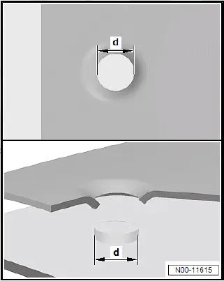
Volkswagen ID.4. Spot weld shear testing
  • Drill/punch upper panel for plug welding (for the hole diameter refer to the vehicle-specific body repair workshop manual).
  • Clean flanges, and remove oxide layer.
  • Perform plug welding from the middle working outwards.

Continuous seam and stepped seam welding - shielding gas

SG continuous seam or stepped seam welding are used for joining butt-type or overlapping cutting points. Due to the very high welding temperatures and the resulting modified properties of modern materials, the area of application for this joining process is more and more restricted. Note vehicle-specific body repair workshop manual for this.

MIG brazing

MIG brazing mainly differs from SG continuous seam and stepped seam welding through the considerably lower temperatures.

MIG brazing

  • A brazing technique also called metal inert gas welding.
  • The inert gas does not actively participate in the processes between the electric arc and the welding filler metal.
  • Argon or helium mixed with carbon dioxide or oxygen are among the used shielding gas types.
  • The base material (body panel) is not melted, the solder wets the edges and connects the components.

Advantages of MIG brazing:

  • Reduced material distortion.
  • Only minor structural modification in the components.
  • Less impairment of the corrosion protection established during production
  • Preservation of zinc coating on the components.

Aluminium welding

The manufacturer and the after-sales service apply metal inert gas welding (MIG).

Argon is used as shielding gas.

  • Remove underseal and paint from parts prior to welding.
  • Then, use a stainless steel brush to remove the oxide layer over a width of approx. 40 mm on both sides.
  • To avoid the formation of cracks, always draw weld seams around profile corners.

Put backing plate underneath:

  • The backing plate -C- is produced from the remainders of the new part -B- or the old part -A-. The backing plate must also be put underneath joggled panel edges. For small cross-sections or large panel edges, the backing plate is separated.
  • Chamfer both panels by 45º. Round off outer edge (radius = -R3-) and chamfer inner edge.
  • The panel tips must have a distance of 3 to 4 mm to each other.
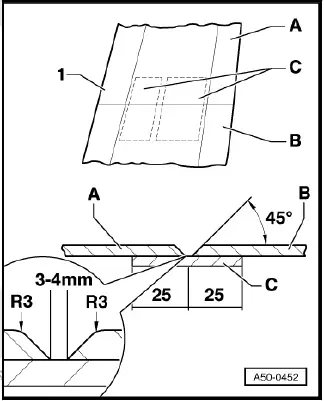
Volkswagen ID.4. Aluminium welding