Windscreen wiper system

In this manual: Windscreen wiper system
Basic information on body repairs — 1Explanation of symbols — 1Overview of materials used — 1Joining and separating techniques — 1Surface repair — 1Corrosion protection — 1Noise insulation — 1Plastic repair — 1General notes - windows — 1Self-adhesive components — 1Noises — 1Resistance spot welding — 1Solid rivet — 1Pop rivet — 1Incorrect riveting — 1Overview of riveting attachments — 1Making a flow-drill screw connection, pre-drilled hole in upper part — 1Distinction of types of plastic — 1Processing instructions - original products — 1Preparing plastic repair — 1Repairing deformations — 1Bonding plastic attachments — 1Welding plastic attachments — 1Glass repair- Introduction — 1Carrying out glass repair — 1General notes on the use of adhesives — 1Preparing old undamaged windows for installing — 1Preparing new windows for installation — 1Installation instructions for bonded windows — 1Bonding log — 1Preparing gas strut for disposal — 1Preparing rear lid drive unit VX69/rear lid drive unit 2 VX77 for disposal — 1Causes of water ingress — 1Locating water ingress — 1Interior equipment — 1Compartments/covers — 1Equipment — 1Centre console — 1Front centre armrest — 1Interior mirror — 1Passenger protection — 1Seat belts — 1Child seat anchors — 1Airbag system — 1Airbag control unit — 1Front airbag, driver side — 1Front passenger airbag — 1Side airbags — 1Curtain airbags — 1Airbag crash sensors — 1Seat belt verification — 1Seat occupied recognition — 1Trim, insulation — 1Front door trims — 1Rear door trims — 1Dash panel — 1Central tube for dash panel — 1Interior trims — 1Luggage compartment trims — 1Roof trims — 1Seat frames — 1Overview of seat variants — 1Front seats — 1Rear seats — 1Seat - padding, covers — 1Front seat covers and padding — 1Rear seat covers and padding — 1Technical data — 1Body - front — 1Lock carrier — 1Wings — 1Technical data — 1Air conditioning system — 1Overview of fitting locations - air conditioning system, R134a/R1234yf — 1Overview of fitting locations - air conditioning system, R744 — 1Refrigerant circuit, R134a/R1234yf — 1Refrigerant circuit, R744 — 1Valve unit of heat pump, R744 — 1Air conditioner compressor, R134a/R1234yf — 1Air conditioner compressor, R744 — 1Control motors, vehicles without air conditioner operating unit at rear — 1Control motors, vehicles with air conditioner operating unit at rear — 1Front heater and air conditioning unit, R134a/R1234yf — 1Front heater and air conditioning unit, R744 — 1Air duct — 1Coolant circuit, rear-wheel drive — 1Coolant circuit, all-wheel drive — 1Operating and display unit — 1Other controlling and regulating components — 1Air quality improvement system — 1Technical data — 1Brake test — 1Electrical components — 1Anti-lock brake system — 1Control unit and hydraulic unit — 1Separating control unit from and connecting to hydraulic unit — 1Connecting brake lines to hydraulic unit — 1Sensors — 1Brakes - mechanism — 1Front brake — 1Rear brake — 1Parking brake — 1Brake pedal — 1Brakes - hydraulics — 1Brake servo and brake master cylinder — 1Hydraulic system — 1Technical data — 1Fitting locations — 1Senders/sensors/control units — 1Adaptive cruise control — 1Reversing camera system — 1Front camera for driver assist systems — 1Overhead view camera — 1Electric drive systems- Safety information and repair notes — 1Classifying high-voltage batteries — 1Packaging high-voltage batteries — 1Packaging critical high-voltage batteries with "Warning" status — 1Bulkhead — 1Bonnet, rear lid — 1Bonnet — 1Rear lid — 1Charging flap unit — 1Front doors, door components, central locking — 1Door — 1Door components — 1Central locking — 1Rear doors, door components — 1Door — 1Door components — 1Sunroof — 1Sliding sunroof — 1Water drain hoses — 1Bumpers — 1Bumper, front — 1Bumper, rear — 1Glazing — 1Windscreen — 1Rear windscreen — 1Side windows — 1Door windows — 1Exterior equipment — 1Spoiler — 1Mouldings, trims, extensions — 1Underbody cladding — 1Roof moulding and roof railing — 1Exterior mirror — 1Wheel housing liner — 1Lettering and emblems — 1Towing bracket — 1Technical data — 1Vehicle identification data — 1Safety information — 1Body parts and materials — 1Technical data — 1Alignment jig — 1Body - front — 1Overview of fitting locations — 1Longitudinal member cross panel — 1Longitudinal member — 1Assembly overview - front right longitudinal member, part section — 1Battery tray — 1Front wheel housing — 1Body - centre — 1Overview of fitting locations — 1Roof — 1A-pillar — 1B-pillar — 1Side member — 1Body - rear — 1Rear cross member — 1Rear cross panel — 1Luggage compartment floor — 1Rear longitudinal member — 1Side panel — 1Rear wheel housing — 1Technical data — 1Controls, housing — 1Removing and installing gearbox — 1Gearbox housing, clutch housing — 1Final drive - differential — 1Technical data — 1Controls, housing — 1Gearbox housing, clutch housing — 1Gear oil — 1Final drive - differential — 1Explanation of symbols — 1Paintwork structure — 1Areas exposed to stone chipping — 1Seam seals, front body — 1Seam seals, bonnet, inner side — 1Seam seals, doors — 1Seam seals, underbody — 1Underseal — 1Cavity sealing — 1Technical data — 1Overview of fitting locations - components/control units in centre section of vehicle — 1Overview of fitting locations - components/control units in rear section of vehicle — 1Overview of fitting locations - components/control units in centre section of vehicle — 1Overview of fitting locations - components/control units in rear section of vehicle — 1Components/control units — 1Multifunction steering wheel — 1Technical data — 1Identification — 1Electrical components — 1Hazard classification of high-voltage system — 1Removing and installing engine — 1Removing and installing front motor — 1Removing and installing rear motor — 1Removing and installing rear motor — 1Front assembly mountings — 1Cooling — 1Cooling system/coolant — 1Coolant pump/coolant regulation — 1Radiator, radiator fan — 1Electric drive systems — 1High-voltage components, charging unit for high-voltage battery and voltage converter — 1High-voltage components, charging unit for high-voltage battery with integrated voltage converter — 1Warning stickers — 1High-voltage battery unit, edge of upper part of battery housing without wax — 1High-voltage battery components, edge of upper part of battery housing without wax — 1High-voltage battery unit, edge of upper part of battery housing with wax — 1High-voltage battery components, edge of upper part of battery housing with wax — 1Power and control electronics for electric drive — 1Electric drive motor — 1Electric drive motor — 1Motor control unit — 1De-energising high-voltage system — 1Potential equalisation lines — 1Charging socket, with charging cable — 1Charging socket, with separate charging cable — 1Charging unit for high-voltage battery — 1Charging unit for high-voltage battery, with integrated voltage converter — 1Vehicle noise/engine sound — 1Accelerator pedal — 1Voltage converter — 1High-voltage cables, all-wheel drive — 1High-voltage cables, rear-wheel drive — 1Technical data — 1Starter, current supply, CCS — 1Assembly overview - battery — 1Removing and installing battery [A] — 1Disconnecting and connecting battery — 1Removing and installing earth wire with battery monitor control unit [J367] — 1Gauges, instruments — 1Dash panel insert — 1Horn — 1Windscreen wash/wipe system — 1Windscreen wiper system — 1Windscreen washer system — 1Rear window wiper system ID4 — 1Rear window washer system — 1Lights, bulbs, switches - exterior — 1Headlights — 1Lights in exterior mirror — 1Tail lights — 1High-level brake light — 1Number plate light — 1Entry and start authorisation system — 1Steering column switch module — 1Towing bracket — 1Lights, bulbs, switches - interior — 1Lights — 1Controls — 1Anti-theft alarm system — 1Cigarette lighter, socket — 1Wiring — 1Relay carriers, fuse holders, electronics boxes — 1Control units — 1Technical data — 1Front suspension — 1Front axle — 1Subframe — 1Suspension strut, upper suspension link — 1Lower suspension link, swivel joint — 1Wheel bearing — 1Drive shaft — 1Anti-roll bar — 1Rear suspension — 1Rear axle — 1Subframe — 1Anti-roll bar — 1Suspension link, track rod — 1Suspension strut, shock absorber, spring — 1Wheel bearing assembly, trailing arm — 1Drive shaft — 1Self-levelling suspension — 1Electronic damping control — 1Vehicle level sender — 1Wheels, tyres, vehicle geometry — 1Wheel alignment — 1Wheels, tyres — 1Steering — 1Steering wheel — 1Steering column — 1Steering rack — 1
2steps
~12min
1/5difficulty
010203040502015N·mlb·ft
Tightening torque found on this page
Done 0 of 2
  • Assembly overview - windscreen wiper system
  • Removing and installing wiper blade
  • Removing and installing wiper arms
  • Adjusting wiper arms
  • Removing and installing wiper motor [V]
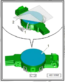
  • Removing and installing rain and light sensor [G397]

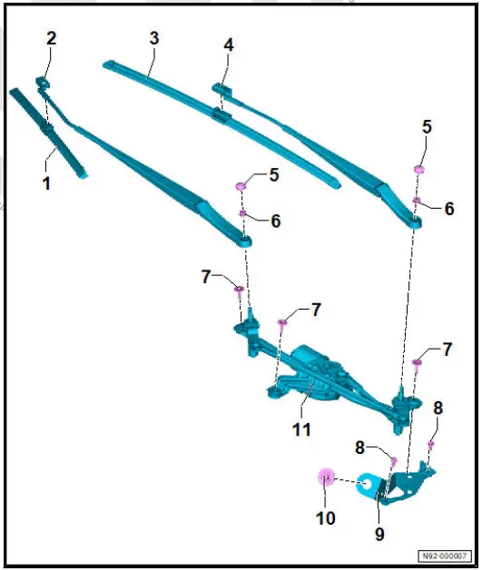
Assembly overview - windscreen wiper system

Volkswagen ID.4. Assembly overview - windscreen wiper system

The overview shows a left-hand drive vehicle as an example.

  1. Wiper blade on front passenger side
  • ⇒ Rep. gr. 92 ; Removing and installing wiper blade
  1. Wiper arm on front passenger side
  • ⇒ Rep. gr. 92 ; Removing and installing wiper arms
  • ⇒ Rep. gr. 92 ; Adjusting wiper arms
  1. Wiper blade on driver side
  • ⇒ Rep. gr. 92 ; Removing and installing wiper blade
  1. Wiper arm on driver side
  • ⇒ Rep. gr. 92 ; Removing and installing wiper arms
  • ⇒ Rep. gr. 92 ; Adjusting wiper arms
  1. Cap
  • Qty. 2
  1. Nut
  • Qty. 2
  • 20 N·m
  1. Bolt
  • Qty. 3
  • Specified torque and tightening sequence
  1. Bolt
  • Qty. 2
  • 8 N·m
  1. Mounting bracket
  2. Bolt
  • 20 N·m
  1. Wiper motor control unit - J400-
  • With wiper motor - V-
  • With windscreen wiper limit switch - F229-
  • ⇒ Rep. gr. 92 ; Removing and installing wiper motor [V]

Removing and installing wiper motor - specified torque and tightening sequence

Volkswagen ID.4. Assembly overview - windscreen wiper system

Moving wipers to service position

NOTICE

The bonnet can be damaged if the wipers are allowed to run back to the park position.

  • Never move the vehicle when the wiper arms are lifted up off the windscreen.

NOTICE

Risk of damage if frozen wiper blades are moved.

  • Allow wiper blades to thaw before operating wipers.

Note

Wiper motor only runs when bonnet is completely closed.

  • Switch ignition on and then off again.
  • Press wiper lever to touch wipe position within 10 seconds.

Removing and installing wiper blade

NOTICE

Risk of damage to windscreen.

  • Make sure wiper arm does not drop back into position unintentionally.

NOTICE

Risk of damage to wiper blade.

  • When lifting wiper blades off windscreen, only take hold of them in vicinity of wiper blade mounting.
  • Avoid bending wiper arm and wiper blade.

Removing

  • ⇒ Rep. gr. 92 ; Move wipers to service position .
  • Lift wiper arm off windscreen.
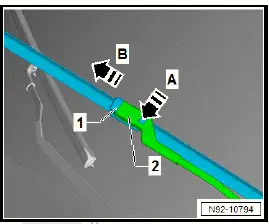
  • Release retaining clip in direction of -arrow A-.
  • Pull wiper blade -1- off wiper arm -2- in direction of -arrow B-.
Volkswagen ID.4. Removing and installing wiper blade

Installing

Installation is carried out in reverse order; note the following:

  • Insert wiper blade -1- into wiper arm -2- in direction of -arrow-, keeping it parallel.
  • Slide wiper blade -1- into wiper arm -2- until retaining clip engages audibly
Volkswagen ID.4. Removing and installing wiper blade
  • Operate touch wipe function to leave service position.

Removing and installing wiper arms

Special tools and workshop equipment required

  • puller - T10369/2-

Removal and installation are described for a left-hand drive vehicle as an example.

Removing

  • ⇒ Rep. gr. 92 ; Move wipers to service position .
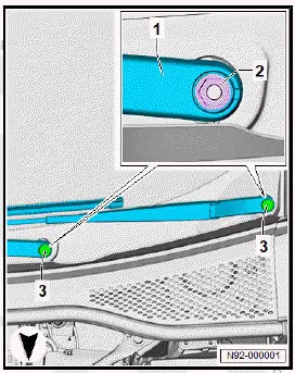
  • Using a suitable screwdriver, lever off cover caps -3-.
  • Loosen nuts -2- a few turns.
Volkswagen ID.4. Removing and installing wiper arms

NOTICE

Risk of damage to wiper arm.

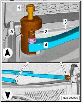
  • Use only puller - T10369/2- .
Volkswagen ID.4. Removing and installing wiper arms
  • Mount puller -A- on wiper arms -3-.
  • Fit thrust piece -2-.
  • Turn bolts -1- clockwise until wiper arms -3- have been pulled off wiper shafts.
  • Remove puller -A-.
  • Unscrew nuts -4-.
  • Remove wiper arms -3-.

Installing

Install in reverse order of removal, observing the following:

  • Switch on ignition.
  • Move wiper arms to end position by actuating "touch wiper".

Note

In service position, move wipers to lowest park position by actuating "touch wipe".

  • Fit both wiper arms on wiper arm shafts in approximate end positions.
  • Screw on nuts of wiper arms and tighten them by hand.
  • ⇒ Rep. gr. 92 ; Adjust wiper arms .

Tightening torques

  • ⇒ Rep. gr. 92 ; Assembly overview - windscreen wiper system

Adjusting wiper arms

Procedure

The adjustment procedure is described for a left-hand drive vehicle as an example.

  • Switch on ignition.
  • Actuate "flick wipe" function and allow wiper arms to move to their end position.
  • Switch off ignition.
  • Loosen wiper arms ⇒ Rep. gr. 92 ; Removing and installing wiper arms .
  • Adjust wiper arms.

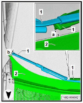
Driver side

Important

  • Distance -a- between end of wiper blade and plenum chamber cover -2- to bottom edge of windscreen must be 12 mm.
  • Adjust wiper blade park position by repositioning wiper arm -1-.
Volkswagen ID.4. Adjusting wiper arms

All vehicles (continued)

Passenger side

Important

  • Distance -b- between end of wiper blade and plenum chamber cover -2- to bottom edge of windscreen must be 13 mm.
  • Adjust wiper blade park position by repositioning wiper arm -1-.
Volkswagen ID.4. Adjusting wiper arms

All vehicles (continued)

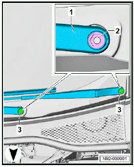
  • Tighten nuts -2- of wiper arms -1-.
  • Switch on ignition.
  • Actuate "flick wipe" function and allow wiper arms -1- to move to their end position.
  • Switch off ignition.
  • Check adjustment of wiper arms -1-.
  • Press caps -3- onto wiper arms -1-.
Volkswagen ID.4. Adjusting wiper arms

Tightening torques

  • ⇒ Rep. gr. 92 ; Assembly overview - windscreen wiper system

Removing and installing wiper motor [V]

Wiper motor control unit - J400- with wiper motor - V- and wiper limit switch - F229- will henceforth be referred to as "wiper motor".

Removal and installation are described for a left-hand drive vehicle as an example.

Removing

If renewing wiper motor:

  • Carry out required function/functions using ⇒ Vehicle diagnostic tester ⇒ Rep. gr. 00 ; Access to diagnoses .

Continued

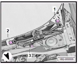
  • Remove plenum chamber cover ⇒ General body repairs, exterior; Rep. gr. 50 ; Plenum chamber bulkhead; Removing and installing plenum chamber cover .

NOTICE

Risk of crushing injury from moving and rotating components of wiper mounting.

  • Do not hold wiper mounting in area of rotating parts.
  • Unscrew bolts -1-.
  • Disconnect electrical connector -2-.
  • Remove rear window wiper motor -3-.
Volkswagen ID.4. Removing and installing wiper motor [V]

Installing

Install in the reverse order of removal, observing the following:

If wiper motor has been renewed:

  • Carry out required function/functions using ⇒ Vehicle diagnostic tester ⇒ Rep. gr. 00 ; Access to diagnoses .

Continued

Tightening torques

  • ⇒ Rep. gr. 92 ; Adjusting wiper arms
  • ⇒ Rep. gr. 92 ; Assembly overview - windscreen wiper system

Removing and installing rain and light sensor [G397]

Rain and light sensor - G397- with humidity sender for air conditioning system - G260- and sunlight penetration photosensor - G107- are referred to hereafter as sensor.

Removing

If sensor is renewed:

  • Carry out required function/functions using ⇒ Vehicle diagnostic tester ⇒ Rep. gr. 00 ; Access to diagnoses .

Continued

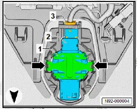
  • Remove interior mirror ⇒ General body repairs, interior; Rep. gr. 68 ; Interior mirror; Removing and installing interior mirror .
  • Disconnect electrical connector -3-.
  • Release fasteners -arrows-.

NOTICE

Risk of damage to the coupling pad if removal is done too abruptly.

  • Wait at least 1 minute to allow the coupling pad to decompress.
Volkswagen ID.4. Removing and installing rain and light sensor [G397]
  • Starting from top, carefully remove sensor -2- from retaining plate for interior mirror.
  • Remove sensor -2-.

Installing

Install in the reverse order of removal, observing the following:

  • Thoroughly clean windscreen in area of interior mirror retaining plate.

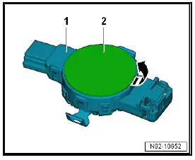
Removed sensor:

  • Pull off coupling pad -2- in direction of -arrow-.

NOTICE

Risk of damage to silicone layer of rain and light sensor.

  • Clean the surface of the rain and light sensor thoroughly.
Volkswagen ID.4. Removing and installing rain and light sensor [G397]
  • Clean sensor -1- by sticking and then peeling off one or several commercially available adhesive strips on bonding surface of sensor -1-.
  • Clean bonding surface of sensor -1- with lint-free cleaning cloth.
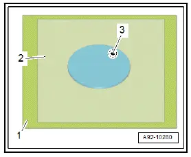
  • Pull silicone paper -1- off coupling pad -3-.

Important

  • Protective film -2- must remain on coupling pad -3-.
Volkswagen ID.4. Removing and installing rain and light sensor [G397]
  • With aid of protective film -1-, position coupling pad -2- centrally on sensor -3-.
  • Press on coupling pad -2- with protective film -1- free of bubbles.
Volkswagen ID.4. Removing and installing rain and light sensor [G397]
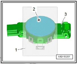
  • Pull off protective film -2-.
Volkswagen ID.4. Removing and installing rain and light sensor [G397]

All vehicles (continued)

New sensor:

  • Press grip in direction of arrows -A-.
  • Remove protective cap -1- in direction of -arrow B-.
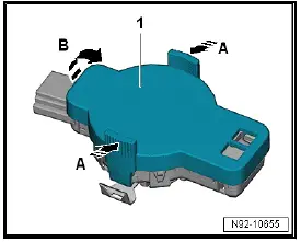
Volkswagen ID.4. Removing and installing rain and light sensor [G397]

All vehicles (continued)

  • Insert sensor -2- in retaining plate for interior mirror.

NOTICE

Malfunctions of rain and light sensor.

  • If the contact surface is not free of bubbles after 10 minutes, the rain and light sensor must be removed and inserted anew.
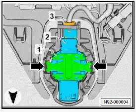
Volkswagen ID.4. Removing and installing rain and light sensor [G397]

Important

  • Retaining clip -1- must engage audibly.
  • Press on retaining clip.
  • Connect electrical connector -3-.

If sensor has been renewed:

  • Carry out required function/functions using ⇒ Vehicle diagnostic tester ⇒ Rep. gr. 00 ; Access to diagnoses .