Airbag crash sensors
- Assembly overview - crash sensors for airbags
- Removing and installing crash sensor for front airbag [G283]/[G284]
- Removing and installing front side airbag crash sensor [G179/G180]
- Removing and installing rear side airbag crash sensor [G256/G257]
- Removing and installing crash sensor for side airbag in B-pillar [G1101/G1102]
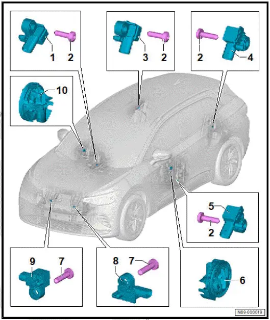
Assembly overview - crash sensors for airbags
- Crash sensor for side airbag in B-pillar
- LHD vehicles: crash sensor for side airbag in B-pillar, passenger side - G1102-
- RHD vehicles: crash sensor for side airbag in B-pillar, driver side - G1101-
- ⇒ Rep. gr. 69 ; Removing and installing crash sensor for side airbag in B-pillar [G1101/G1102]
- Bolt
- 8 N·m
- Rear side airbag crash sensor
- Left-hand drive vehicles: rear side airbag crash sensor on passenger side - G257-
- Right-hand drive vehicles: rear side airbag crash sensor on driver side - G256-
- ⇒ Rep. gr. 69 ; Removing and installing rear side airbag crash sensor [G256/G257]
- Rear side airbag crash sensor
- Left-hand drive vehicles: rear side airbag crash sensor on driver side - G256-
- Right-hand drive vehicles: rear side airbag crash sensor on passenger side - G257-
- ⇒ Rep. gr. 69 ; Removing and installing rear side airbag crash sensor [G256/G257]
- Crash sensor for side airbag in B-pillar
- LHD vehicles: crash sensor for side airbag in B-pillar, driver side - G1101-
- RHD vehicles: crash sensor for side airbag in B-pillar, passenger side - G1102-
- ⇒ Rep. gr. 69 ; Removing and installing crash sensor for side airbag in B-pillar [G1101/G1102]
- Side airbag crash sensor, driver side
- Left-hand drive vehicles: side airbag crash sensor on driver side - G179-
- Right-hand drive vehicles: side airbag crash sensor on passenger side - G180-
- ⇒ Rep. gr. 69 ; Removing and installing front side airbag crash sensor [G179/G180]
- - Bolt
- 9 N·m
- Crash sensor for front airbag
- Left-hand drive vehicles: front airbag crash sensor for driver side - G283-
- RHD vehicles: front airbag crash sensor for front passenger side - G284-
- ⇒ Rep. gr. 69 ; Removing and installing crash sensor for front airbag [G190]/[G284]
- Crash sensor for front airbag
- RHD vehicles: front airbag crash sensor for front passenger side - G284-
- Right-hand drive vehicles: front airbag crash sensor for driver side - G283-
- ⇒ Rep. gr. 69 ; Removing and installing crash sensor for front airbag [G190]/[G284]
- Side airbag crash sensor, front passenger side
- Left-hand drive vehicles: side airbag crash sensor on front passenger side - G180-
- Right-hand drive vehicles: side airbag crash sensor on driver side - G179-
- ⇒ Rep. gr. 69 ; Removing and installing front side airbag crash sensor [G179/G180]
Removing and installing crash sensor for front airbag [G283]/[G284]
Front airbag crash sensor for driver side - G283- and front airbag crash sensor for front passenger side - G284- are referred to hereafter as "crash sensor".
Removal and installation are described for the left side of vehicle as an example.
Removing
WARNING
Risk of airbag being triggered Risk of injury
- Check whether airbag warning lamp is on or is flashing.
- If airbag warning lamp is on or flashing, read out event memory.
- If event memory shows entry "Short to positive", disconnect battery: "Electrical system; Rep. gr. 27; Battery; Disconnecting and connecting battery".
- Follow instructions in Guided Fault Finding if there is an entry in the event memory.
- If airbag warning lamp is not on or flashing, switch ignition off. Deposit vehicle key and other drive authorisation systems (e.g. smartphone) outside vehicle and wait 10 seconds.
- Disconnect battery earth cable ⇒ Electrical system; Rep.
gr. 27 ; Battery; Disconnecting and connecting battery .
- Remove bumper cover ⇒ General body repairs, exterior; Rep. gr. 63 ; Front bumper; Removing and installing bumper cover .
- Remove lock carrier support ⇒ General body repairs, exterior; Rep. gr. 50 ; Lock carrier, Removing and installing lock carrier support .
CAUTION
It is possible to trigger pyrotechnic components unintentionally.
Risk of injury
- Discharge static electricity by briefly touching door striker plate.
- Unscrew bolt -3-.
- Detach crash sensor -1-.
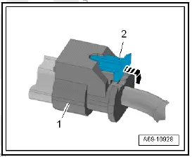
- Disconnect electrical connector -2-.
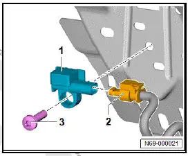
- To do this, pull out connector lock -2-, and push it down in direction of -arrow-.
Installing
Install in reverse order of removal, observing the following:
- Connect battery earth cable ⇒ Electrical system; Rep.
gr. 27 ; Battery; Disconnecting and connecting battery .
CAUTION
It is possible to trigger pyrotechnic components unintentionally.
Risk of injury.
- Stay as far back as possible from pyrotechnic components when switching on the ignition.
- Switch on ignition.
- Read and clear event memory using ⇒ Vehicle diagnostic tester.
Tightening torques
- ⇒ Rep. gr. 69 ; Assembly overview - crash sensors for airbags
Removing and installing front side airbag crash sensor [G179/G180]
Side airbag crash sensor on driver side - G179- and side airbag crash sensor on front passenger side - G180- are referred to hereafter as crash sensor.
Removal and installation are described for the left side of vehicle as an example.
Removing
WARNING
Risk of airbag being triggered
Risk of injury
- Check whether airbag warning lamp is on or is flashing.
- If airbag warning lamp is on or flashing, read out event memory.
- If event memory shows entry "Short to positive", disconnect battery: "Electrical system; Rep. gr. 27; Battery; Disconnecting and connecting battery".
- Follow instructions in Guided Fault Finding if there is an entry in the event memory.
- If airbag warning lamp is not on or flashing, switch ignition off. Deposit vehicle key and other drive authorisation systems (e.g. smartphone) outside vehicle and wait 10 seconds.
- Disconnect battery earth cable ⇒ Electrical system; Rep.
gr. 27 ; Battery; Disconnecting and connecting battery .
- Remove front door trim ⇒ Rep. gr. 70 ; Removing and installing front door trim .
CAUTION
It is possible to trigger pyrotechnic components unintentionally.
Risk of injury
- Discharge static electricity by briefly touching door striker plate.
- Pull out connector lock, and release it.
- Disconnect electrical connector.
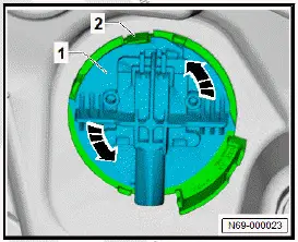
- Release locating element -2- and turn crash sensor -1- 45º in direction of -arrow-.
- Detach and remove crash sensor -1-.
Installing
Install in reverse order of removal, observing the following:
Important
- Make sure that door forms an effective seal.
- Connect battery earth cable ⇒ Electrical system; Rep.
gr. 27 ; Battery; Disconnecting and connecting battery .
CAUTION
It is possible to trigger pyrotechnic components unintentionally.
Risk of injury.
- Stay as far back as possible from pyrotechnic components when switching on the ignition.
- Switch on ignition.
- Read and clear event memory using ⇒ Vehicle diagnostic tester.
Removing and installing rear side airbag crash sensor [G256/G257]
Rear side airbag crash sensor on driver side - G256- and rear side airbag crash sensor on passenger side - G257- will henceforth be referred to as "crash sensor".
Removal and installation are described for the left side of vehicle as an example.
Removing
WARNING
Risk of airbag being triggered
Risk of injury
- Check whether airbag warning lamp is on or is flashing.
- If airbag warning lamp is on or flashing, read out event memory.
- If event memory shows entry "Short to positive", disconnect battery: "Electrical system; Rep. gr. 27; Battery; Disconnecting and connecting battery".
- Follow instructions in Guided Fault Finding if there is an entry in the event memory.
- If airbag warning lamp is not on or flashing, switch ignition off. Deposit vehicle key and other drive authorisation systems (e.g. smartphone) outside vehicle and wait 10 seconds.
- Disconnect battery earth cable ⇒ Electrical system; Rep.
gr. 27 ; Battery; Disconnecting and connecting battery .
- Remove rear sill panel moulding ⇒ Rep. gr. 70 ; Removing and installing rear sill panel moulding .
CAUTION
It is possible to trigger pyrotechnic components unintentionally.
Risk of injury
- Discharge static electricity by briefly touching door striker plate.
- Pull out connector lock, and release it.
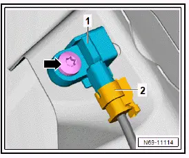
- Disconnect electrical connector -2-.
- Unscrew bolt -arrow-.
- Detach crash sensor -1-.
Installing
Install in reverse order of removal, observing the following:
- Connect electrical connector until it engages audibly.
- Make sure that electrical wire is not trapped.
- Connect battery earth cable ⇒ Electrical system; Rep.
gr. 27 ; Battery; Disconnecting and connecting battery .
CAUTION
It is possible to trigger pyrotechnic components unintentionally.
Risk of injury.
- Stay as far back as possible from pyrotechnic components when switching on the ignition.
- Switch on ignition.
- Read and clear event memory using ⇒ Vehicle diagnostic tester.
Tightening torques
- ⇒ Rep. gr. 69 ; Assembly overview - crash sensors for airbags
Removing and installing crash sensor for side airbag in B-pillar [G1101/G1102]
Crash sensor for side airbag in B-pillar, driver side - G1101- and crash sensor for side airbag in B-pillar, passenger side - G1102- will henceforth be referred to as "crash sensor".
Removal and installation are described for the left side of vehicle as an example.
Removing
WARNING
Risk of airbag being triggered
Risk of injury
- Check whether airbag warning lamp is on or is flashing.
- If airbag warning lamp is on or flashing, read out event memory.
- If event memory shows entry "Short to positive", disconnect battery: "Electrical system; Rep. gr. 27; Battery; Disconnecting and connecting battery".
- Follow instructions in Guided Fault Finding if there is an entry in the event memory.
- If airbag warning lamp is not on or flashing, switch ignition off. Deposit vehicle key and other drive authorisation systems (e.g. smartphone) outside vehicle and wait 10 seconds.
- Disconnect battery earth cable ⇒ Electrical system; Rep.
gr. 27 ; Battery; Disconnecting and connecting battery .
Vehicles with one-piece sill panel moulding
- Remove sill panel moulding ⇒ Rep. gr. 70 ; Removing and installing front sill panel moulding .
All vehicles (continued)
Vehicles with two-piece sill panel moulding
- Remove rear sill panel moulding ⇒ General body repairs, interior; Rep. gr. 70 ; Trims, interior; Removing and installing rear sill panel moulding .
All vehicles (continued)
- Remove lower B-pillar trim ⇒ Rep. gr. 70 ; Removing and installing lower B-pillar trim .
CAUTION
It is possible to trigger pyrotechnic components unintentionally.
Risk of injury
- Discharge static electricity by briefly touching door striker plate.
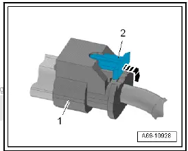
- Unscrew bolt -arrow-.
- Detach crash sensor -1-.
- Disconnect electrical connector -2-.

- To do this, pull out connector lock -2-, and push it down in direction of -arrow-.
Installing
Install in reverse order of removal, observing the following:
- Connect battery earth cable ⇒ Electrical system; Rep.
gr. 27 ; Battery; Disconnecting and connecting battery .
CAUTION
It is possible to trigger pyrotechnic components unintentionally.
Risk of injury.
- Stay as far back as possible from pyrotechnic components when switching on the ignition.
- Switch on ignition.
- Read and clear event memory using ⇒ Vehicle diagnostic tester.
Tightening torques
- ⇒ Rep. gr. 69 ; Assembly overview - crash sensors for airbags