Electronic damping control
- Overview of fitting locations - damping control
- Assembly overview - electronically controlled damping control unit
- Removing and installing electronically controlled damping control unit [J250]
- Removing and installing front body acceleration senders [G341]/[G342]
- Removing and installing rear body acceleration sender [G343]
Overview of fitting locations - damping control
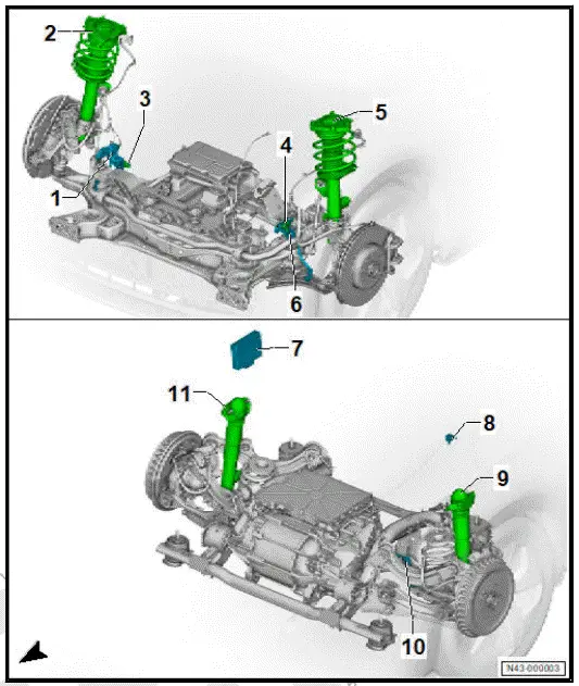
- Front right body acceleration sender - G342-
- ⇒ Rep. gr. 43 ; Assembly overview - electronically controlled damping
- ⇒ Rep. gr. 43 ; Removing and installing front body acceleration senders [G341]/[G342]
- Shock absorber with front right shock absorber damper adjustment valve - N337-
- ⇒ Rep. gr. 42 ; Assembly overview - shock absorber
- ⇒ Rep. gr. 42 ; Removing and installing shock absorber
- Front right vehicle level sender - G289-
- ⇒ Rep. gr. 43 ; Assembly overview - front vehicle level senders
- ⇒ Rep. gr. 43 ; Removing and installing front vehicle level senders [G78]/[G289]
- Front left body acceleration sender - G341-
- ⇒ Rep. gr. 43 ; Assembly overview - electronically controlled damping
- ⇒ Rep. gr. 43 ; Removing and installing front body acceleration senders [G341]/[G342]
- Shock absorber with front left shock absorber damper adjustment valve - N336-
- ⇒ Rep. gr. 42 ; Assembly overview - shock absorber
- ⇒ Rep. gr. 42 ; Removing and installing shock absorber
- Front left vehicle level sender - G78-
- ⇒ Rep. gr. 43 ; Assembly overview - front vehicle level senders
- ⇒ Rep. gr. 43 ; Removing and installing front vehicle level senders [G78]/[G289]
- Electronically controlled damping control unit - J250-
- ⇒ Rep. gr. 43 ; Assembly overview - electronically controlled damping control unit
- ⇒ Rep. gr. 43 ; Removing and installing electronically controlled damping control unit [J250]
- Rear body acceleration sender - G343-
- ⇒ Rep. gr. 43 ; Assembly overview - electronically controlled damping
- ⇒ Rep. gr. 43 ; Removing and installing rear body acceleration sender [G343]
- Shock absorber with rear left shock absorber damper adjustment valve - N338- .
- ⇒ Rep. gr. 42 ; Assembly overview - shock absorber
- ⇒ Rep. gr. 42 ; Removing and installing shock absorber
- Rear left vehicle level sender - G76-
- ⇒ Rep. gr. 43 ; Assembly overview - rear vehicle level senders
- ⇒ Rep. gr. 43 ; Removing and installing rear vehicle level senders [G76]/[G77]
- Shock absorber with rear right shock absorber damper adjustment valve - N339- .
- ⇒ Rep. gr. 42 ; Assembly overview - shock absorber
- ⇒ Rep. gr. 42 ; Removing and installing shock absorber
Assembly overview - electronically controlled damping control unit
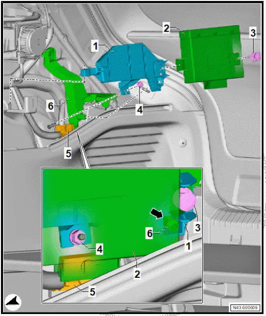
- Bracket for electronically controlled damping control unit - J250-
- Electronically controlled damping control unit - J250-
- ⇒ Rep. gr. 43 ; Removing and installing electronically controlled damping control unit [J250]
- Retaining clip
- Depending on equipment/ version
- Nut
- 2,5 N·m
- Electrical connector
- Bracket
Exploded view - damping control
The exploded view here applies to the left side of the vehicle.
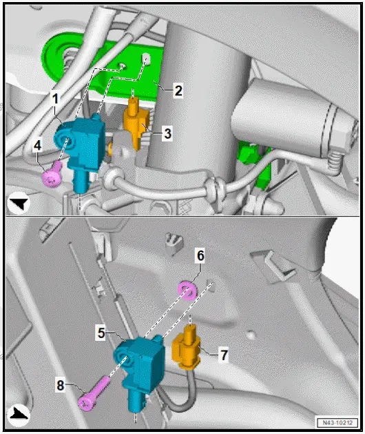
- Front left body acceleration sender - G341- / front right body acceleration sender - G342-
- ⇒ Rep. gr. 43 ; Removing and installing front body acceleration senders G341/G342
- Bracket
- Electrical connector
- Bolt
- M 6 x 16
- 8 N·m
- Rear body acceleration sender - G343-
- ⇒ Rep. gr. 43 ; Removing and installing rear body acceleration sender G343
- Pop rivet nut
- Electrical connector
- Bolt
- M 6 x 25
- 8 N·m
Removing and installing electronically controlled damping control unit [J250]
Removing
The electronically controlled damping control unit - J250- will henceforth be referred to as "control unit".
- If the control unit is renewed, perform the test plan for the renewal of the control unit ⇒ Vehicle diagnostic tester.
- Remove right luggage compartment side trim ⇒ General body repairs, interior; Rep. gr. 70 ; Luggage compartment trims; Removing and installing luggage compartment side trim .
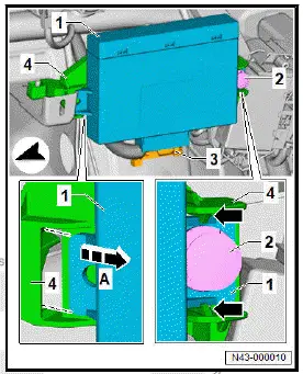
- Disconnect electrical connector -3-.
- Release and remove retaining clip -2-.
- Unclip control unit -1- on right side -arrows-.
- Pull control unit -1- in direction of -arrow A- out of bracket -4-.
Installing
Install in reverse order of removal, observing the following:
- If the control unit has been renewed, conclude the test plan for the renewal of control unit. ⇒ Vehicle diagnostic tester ⇒ Rep. gr. 00 ; Access to diagnoses .
Removing and installing front body acceleration senders [G341]/[G342]
Removing
The front left body acceleration sender - G341- and front right speed sensor - G342- will be henceforth referred to as the "front body acceleration sender".
Removal and installation are described for the left side of vehicle as an example.
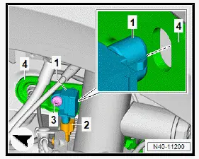
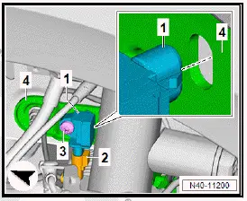
- Disconnect electrical connector -2-.
- Unscrew bolt -3- from bracket -4-, and remove front body acceleration sender -1-.
Installing
Install in reverse order of removal, observing the following:
- Insert guide on front body acceleration sender -1- into bracket -4-.
- Carry out basic setting for wheel damping electronics using ⇒ Vehicle diagnostic tester ⇒ Rep. gr. 00 ; Access to diagnoses .
Tightening torques
- ⇒ Rep. gr. 43 ; Assembly overview - electronically controlled damping
Removing and installing rear body acceleration sender [G343]
Removing
The rear body acceleration sender - G343- will henceforth be referred to as "rear body acceleration sender".
Removal and installation are described for the left side of vehicle as an example.
- Remove rear left sill panel moulding ⇒ General body repairs, interior; Rep. gr. 70 ; Trims, interior; Removing and installing rear sill panel moulding .
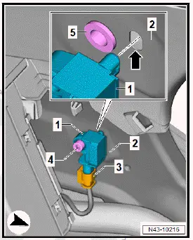
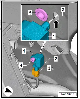
- Disconnect electrical connector -3-.
- Unscrew bolt -4-, and remove rear body acceleration sender -1-.
Installing
Install in reverse order of removal, observing the following:
- Insert guide on rear body acceleration sender -1- into recess in body -arrow-.
- Carry out basic setting for wheel damping electronics using ⇒ Vehicle diagnostic tester ⇒ Rep. gr. 00 ; Access to diagnoses .
Tightening torques
- ⇒ Rep. gr. 43 ; Assembly overview - electronically controlled damping