Lettering and emblems

In this manual: Lettering and emblems
Basic information on body repairs — 1Explanation of symbols — 1Overview of materials used — 1Joining and separating techniques — 1Surface repair — 1Corrosion protection — 1Noise insulation — 1Plastic repair — 1General notes - windows — 1Self-adhesive components — 1Noises — 1Resistance spot welding — 1Solid rivet — 1Pop rivet — 1Incorrect riveting — 1Overview of riveting attachments — 1Making a flow-drill screw connection, pre-drilled hole in upper part — 1Distinction of types of plastic — 1Processing instructions - original products — 1Preparing plastic repair — 1Repairing deformations — 1Bonding plastic attachments — 1Welding plastic attachments — 1Glass repair- Introduction — 1Carrying out glass repair — 1General notes on the use of adhesives — 1Preparing old undamaged windows for installing — 1Preparing new windows for installation — 1Installation instructions for bonded windows — 1Bonding log — 1Preparing gas strut for disposal — 1Preparing rear lid drive unit VX69/rear lid drive unit 2 VX77 for disposal — 1Causes of water ingress — 1Locating water ingress — 1Interior equipment — 1Compartments/covers — 1Equipment — 1Centre console — 1Front centre armrest — 1Interior mirror — 1Passenger protection — 1Seat belts — 1Child seat anchors — 1Airbag system — 1Airbag control unit — 1Front airbag, driver side — 1Front passenger airbag — 1Side airbags — 1Curtain airbags — 1Airbag crash sensors — 1Seat belt verification — 1Seat occupied recognition — 1Trim, insulation — 1Front door trims — 1Rear door trims — 1Dash panel — 1Central tube for dash panel — 1Interior trims — 1Luggage compartment trims — 1Roof trims — 1Seat frames — 1Overview of seat variants — 1Front seats — 1Rear seats — 1Seat - padding, covers — 1Front seat covers and padding — 1Rear seat covers and padding — 1Technical data — 1Body - front — 1Lock carrier — 1Wings — 1Technical data — 1Air conditioning system — 1Overview of fitting locations - air conditioning system, R134a/R1234yf — 1Overview of fitting locations - air conditioning system, R744 — 1Refrigerant circuit, R134a/R1234yf — 1Refrigerant circuit, R744 — 1Valve unit of heat pump, R744 — 1Air conditioner compressor, R134a/R1234yf — 1Air conditioner compressor, R744 — 1Control motors, vehicles without air conditioner operating unit at rear — 1Control motors, vehicles with air conditioner operating unit at rear — 1Front heater and air conditioning unit, R134a/R1234yf — 1Front heater and air conditioning unit, R744 — 1Air duct — 1Coolant circuit, rear-wheel drive — 1Coolant circuit, all-wheel drive — 1Operating and display unit — 1Other controlling and regulating components — 1Air quality improvement system — 1Technical data — 1Brake test — 1Electrical components — 1Anti-lock brake system — 1Control unit and hydraulic unit — 1Separating control unit from and connecting to hydraulic unit — 1Connecting brake lines to hydraulic unit — 1Sensors — 1Brakes - mechanism — 1Front brake — 1Rear brake — 1Parking brake — 1Brake pedal — 1Brakes - hydraulics — 1Brake servo and brake master cylinder — 1Hydraulic system — 1Technical data — 1Fitting locations — 1Senders/sensors/control units — 1Adaptive cruise control — 1Reversing camera system — 1Front camera for driver assist systems — 1Overhead view camera — 1Electric drive systems- Safety information and repair notes — 1Classifying high-voltage batteries — 1Packaging high-voltage batteries — 1Packaging critical high-voltage batteries with "Warning" status — 1Bulkhead — 1Bonnet, rear lid — 1Bonnet — 1Rear lid — 1Charging flap unit — 1Front doors, door components, central locking — 1Door — 1Door components — 1Central locking — 1Rear doors, door components — 1Door — 1Door components — 1Sunroof — 1Sliding sunroof — 1Water drain hoses — 1Bumpers — 1Bumper, front — 1Bumper, rear — 1Glazing — 1Windscreen — 1Rear windscreen — 1Side windows — 1Door windows — 1Exterior equipment — 1Spoiler — 1Mouldings, trims, extensions — 1Underbody cladding — 1Roof moulding and roof railing — 1Exterior mirror — 1Wheel housing liner — 1Lettering and emblems — 1Towing bracket — 1Technical data — 1Vehicle identification data — 1Safety information — 1Body parts and materials — 1Technical data — 1Alignment jig — 1Body - front — 1Overview of fitting locations — 1Longitudinal member cross panel — 1Longitudinal member — 1Assembly overview - front right longitudinal member, part section — 1Battery tray — 1Front wheel housing — 1Body - centre — 1Overview of fitting locations — 1Roof — 1A-pillar — 1B-pillar — 1Side member — 1Body - rear — 1Rear cross member — 1Rear cross panel — 1Luggage compartment floor — 1Rear longitudinal member — 1Side panel — 1Rear wheel housing — 1Technical data — 1Controls, housing — 1Removing and installing gearbox — 1Gearbox housing, clutch housing — 1Final drive - differential — 1Technical data — 1Controls, housing — 1Gearbox housing, clutch housing — 1Gear oil — 1Final drive - differential — 1Explanation of symbols — 1Paintwork structure — 1Areas exposed to stone chipping — 1Seam seals, front body — 1Seam seals, bonnet, inner side — 1Seam seals, doors — 1Seam seals, underbody — 1Underseal — 1Cavity sealing — 1Technical data — 1Overview of fitting locations - components/control units in centre section of vehicle — 1Overview of fitting locations - components/control units in rear section of vehicle — 1Overview of fitting locations - components/control units in centre section of vehicle — 1Overview of fitting locations - components/control units in rear section of vehicle — 1Components/control units — 1Multifunction steering wheel — 1Technical data — 1Identification — 1Electrical components — 1Hazard classification of high-voltage system — 1Removing and installing engine — 1Removing and installing front motor — 1Removing and installing rear motor — 1Removing and installing rear motor — 1Front assembly mountings — 1Cooling — 1Cooling system/coolant — 1Coolant pump/coolant regulation — 1Radiator, radiator fan — 1Electric drive systems — 1High-voltage components, charging unit for high-voltage battery and voltage converter — 1High-voltage components, charging unit for high-voltage battery with integrated voltage converter — 1Warning stickers — 1High-voltage battery unit, edge of upper part of battery housing without wax — 1High-voltage battery components, edge of upper part of battery housing without wax — 1High-voltage battery unit, edge of upper part of battery housing with wax — 1High-voltage battery components, edge of upper part of battery housing with wax — 1Power and control electronics for electric drive — 1Electric drive motor — 1Electric drive motor — 1Motor control unit — 1De-energising high-voltage system — 1Potential equalisation lines — 1Charging socket, with charging cable — 1Charging socket, with separate charging cable — 1Charging unit for high-voltage battery — 1Charging unit for high-voltage battery, with integrated voltage converter — 1Vehicle noise/engine sound — 1Accelerator pedal — 1Voltage converter — 1High-voltage cables, all-wheel drive — 1High-voltage cables, rear-wheel drive — 1Technical data — 1Starter, current supply, CCS — 1Assembly overview - battery — 1Removing and installing battery [A] — 1Disconnecting and connecting battery — 1Removing and installing earth wire with battery monitor control unit [J367] — 1Gauges, instruments — 1Dash panel insert — 1Horn — 1Windscreen wash/wipe system — 1Windscreen wiper system — 1Windscreen washer system — 1Rear window wiper system ID4 — 1Rear window washer system — 1Lights, bulbs, switches - exterior — 1Headlights — 1Lights in exterior mirror — 1Tail lights — 1High-level brake light — 1Number plate light — 1Entry and start authorisation system — 1Steering column switch module — 1Towing bracket — 1Lights, bulbs, switches - interior — 1Lights — 1Controls — 1Anti-theft alarm system — 1Cigarette lighter, socket — 1Wiring — 1Relay carriers, fuse holders, electronics boxes — 1Control units — 1Technical data — 1Front suspension — 1Front axle — 1Subframe — 1Suspension strut, upper suspension link — 1Lower suspension link, swivel joint — 1Wheel bearing — 1Drive shaft — 1Anti-roll bar — 1Rear suspension — 1Rear axle — 1Subframe — 1Anti-roll bar — 1Suspension link, track rod — 1Suspension strut, shock absorber, spring — 1Wheel bearing assembly, trailing arm — 1Drive shaft — 1Self-levelling suspension — 1Electronic damping control — 1Vehicle level sender — 1Wheels, tyres, vehicle geometry — 1Wheel alignment — 1Wheels, tyres — 1Steering — 1Steering wheel — 1Steering column — 1Steering rack — 1
~5min read
0102030405021N·mlb·ft
Tightening torque found on this page
  • Assembly overview - lettering and badges
  • Removing and installing front badge
  • Renewing lettering and badges on sides
  • Removing and installing lettering at rear
  • Removing and installing badge at rear

Assembly overview - lettering and badges

Overview shown for left side of vehicle as an example

  1. Badge at front
  • Depending on equipment/ version
  • ⇒ Rep. gr. 66 ; Removing and installing front badge
  1. Bolt
  • Fitted on selected models
  • Qty. 2
  • 2 N·m
  1. Lettering on wing
  • Fitted on selected models
  • Depending on equipment/ version
  • Renew after removing
  • ⇒ Rep. gr. 66 ; Renewing lettering and badges on sides
  1. Lettering on door
  • Fitted on selected models
  • Depending on equipment/ version
  • Renew after removing
  • ⇒ Rep. gr. 66 ; Renewing lettering and badges on sides
  1. Badge on rear
  • Renew after removing
  • ⇒ Rep. gr. 66 ; Removing and installing badge at rear
  1. Lettering at rear
  • Depending on equipment/version
  • Renew after removing
  • ⇒ Rep. gr. 66 ; Removing and installing lettering at rear
Volkswagen ID.4. Assembly overview - lettering and badges

Removing and installing front badge

The front badge with contour lighting module for front badge - MX16- will henceforth be referred as "front badge".

Removing

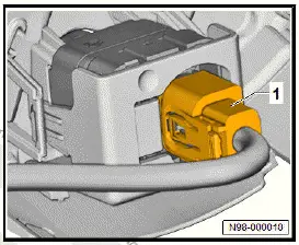
Vehicles with front overhead view camera - R243- in badge

  • Disconnect electrical connector -1-.
Volkswagen ID.4. Removing and installing front badge

All vehicles (continued)

Vehicles with bolts in badge

  • Unscrew bolts -3-.
Volkswagen ID.4. Removing and installing front badge

All vehicles (continued)

  • Release fasteners -2-.
  • Remove front badge -1- in direction of -arrow-.
Volkswagen ID.4. Removing and installing front badge

Installing

Install in reverse order of removal, observing the following:

Vehicles with front overhead view camera - R243- in badge

  • Calibrate front overhead view camera - R243- ⇒ Driver assist systems; Rep. gr. 98 ; Overhead view camera; Calibrating overhead view camera system .

All vehicles (continued)

Tightening torques

  • ⇒ Rep. gr. 66 ; Assembly overview - lettering and badges

Renewing lettering and badges on sides

Special tools and workshop equipment required

  • hot air blower - V.A.G 1416-
  • roller - T40400

Removal and installation are described for the left side of vehicle as an example.

Important

  • Instructions and specifications regarding temperature, minimum drying time, removal of adhesive residue and cleaning must be adhered to ⇒ General information - body; Rep.

    gr. 52 ; Self-adhesive components; Specifications for selfadhesive components .

Removing

  • Apply heat from hot air blower - V.A.G 1416- to lettering.
  • Pull off lettering.

Installing

  • Remove adhesive residue, and clean bonding surfaces.

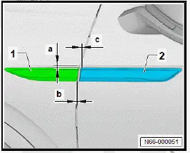
Lettering on wing

  • Fit lettering at wing -1-, taking into account the specified dimensions:
  • Height dimension -a- = 11 mm
  • Side dimension -b- = 0 +-1 mm
Volkswagen ID.4. Renewing lettering and badges on sides

All vehicles (continued)

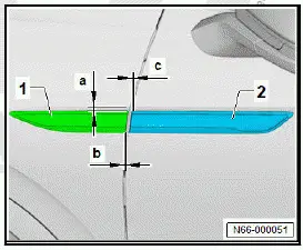
Lettering on front door

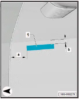
  • Fit door lettering -2- so that it is flush with wing lettering -1-, taking into account the specified dimensions:
  • Side dimension -c- = 0 +-1 mm
Volkswagen ID.4. Renewing lettering and badges on sides

All vehicles (continued)

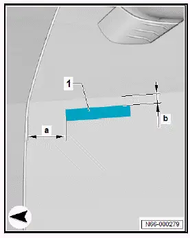
"GTX" lettering on front door

Left side of vehicle

  • Position lettering -1- on door, observing specified dimension:
  • Height dimension -a- = 26.2 +-1 mm
  • Side dimension -b- = 34.7 +-1 mm
Volkswagen ID.4. Renewing lettering and badges on sides

Continued GTX lettering on front door

Right side of vehicle

  • Position lettering -1- on door, observing specified dimension:
  • Height dimension -a- = 26.7 +-1 mm
  • Side dimension -b- = 34.2 +-1 mm
Volkswagen ID.4. Renewing lettering and badges on sides

All vehicles (continued)

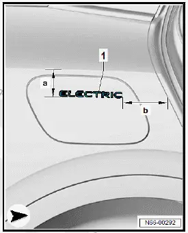
Lettering on charging socket flap

  • Position lettering -1- on charging socket flap, observing specified dimension:
  • Height dimension -a- = 68 +-1 mm
  • Side dimension -b- = 153.5 +-1 mm
Volkswagen ID.4. Renewing lettering and badges on sides

All vehicles (continued)

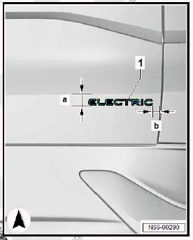
Lettering on side panel

  • Position lettering -1- on side panel, observing specified dimension:
  • Height dimension -a- = 68 +-1 mm
  • Side dimension -b- = 153.5 +-1 mm
Volkswagen ID.4. Renewing lettering and badges on sides

All vehicles (continued)

  • Press on lettering.
  • Use roller - T40400- in area of adhesive tape to press on lettering with a force of 40 N to 50 N.

Important

  • The minimum drying time must be adhered to.

Removing and installing lettering at rear

Special tools and workshop equipment required

  • hot air blower - V.A.G 1416-

Important

  • Instructions and specifications regarding temperature, minimum drying time, removal of adhesive residue and cleaning must be adhered to ⇒ General information - body; Rep.

    gr. 52 ; Self-adhesive components; Specifications for selfadhesive components .

Removing

  • Apply heat from hot air blower - V.A.G 1416- to lettering.
  • Pull off lettering from rear lid.

Installing

  • Remove adhesive residue, and clean bonding surfaces.

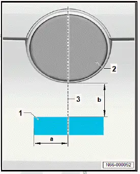
Lettering beneath badge

  • Fit lettering at rear -1-, taking into account the specified dimensions:
  • Badge at rear -2-
  • Centre line -3-
  • Side dimension -a- = 53 +-1 mm
  • Height dimension -b- = 68 +-1 mm
Volkswagen ID.4. Lettering beneath badge

All vehicles (continued)

Rear lid lettering

  • Fit lettering at rear -1-, taking into account the specified dimensions:
  • Height dimension -a- = 37.5 +-1 mm
  • Side dimension -b- = 28 +-1 mm
Volkswagen ID.4. Lettering beneath badge

All vehicles (continued)

  • Press on lettering.
  • Press on lettering at rear -1- with a force of 40 N to 50 N.

Important

  • The minimum drying time must be adhered to.

Removing and installing badge at rear

Special tools and workshop equipment required

  • hot air blower - V.A.G 1416-
  • roller - T40400-

Badge at rear is referred to hereafter as badge.

Important

  • Instructions and specifications regarding temperature, minimum drying time, removal of adhesive residue and cleaning must be adhered to ⇒ General information - body; Rep.

    gr. 52 ; Self-adhesive components; Specifications for selfadhesive components .

Removing

NOTICE

Danger of damage to tail light cluster when dismantling badge.

Tail light trim could crack.

  • When removing upper part of badge, do not press commercially available plastic wedge against tail light.
  • Using commercially available plastic wedge, remove upper part of badge -1- from lower part of badge -2- until holes are visible.
Volkswagen ID.4. Removing and installing badge at rear
  • Apply heat from hot air blower - V.A.G 1416- to lower part of badge -1-.
  • Guide commercially available hook into hole -arrows-.
  • Pull off lower part of badge -1- from tail light.
Volkswagen ID.4. Removing and installing badge at rear

Installing

Install in reverse order of removal, observing the following:

  • Remove adhesive residue, and clean bonding surfaces.
  • Fit badge at rear, and push it on until it can be heard to engage.
  • Roll on badge at rear in area of adhesive tape at a force of 50 N using roller - T40400- .

Important

  • Observe minimum drying time of 24 hours.