Interior trims
- Overview of fitting locations - interior trims
- Assembly overview - sill panel moulding
- Assembly overview - A-pillar trim
- Assembly overview - B-pillar trim
- Assembly overview - C-pillar trim
- Removing and installing front sill panel moulding
- Removing and installing rear sill panel moulding
- Removing and installing upper A-pillar trim
- Removing and installing lower A-pillar trim
- Removing and installing upper B-pillar trim
- Removing and installing lower B-pillar trim
- Removing and installing C-pillar trim
- Removing and installing floor covering
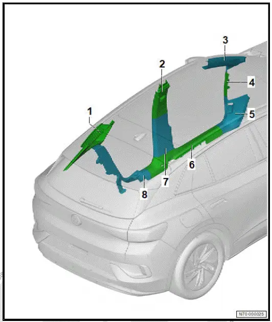
Overview of fitting locations - interior trims
Overview shown for left side of vehicle as an example
- C-pillar trim
- ⇒ Rep. gr. 70 ; Assembly overview - Cpillar trim
- ⇒ Rep. gr. 70 ; Removing and installing C-pillar trim
- Upper part of B-pillar trim
- ⇒ Rep. gr. 70 ; Assembly overview - Bpillar trim
- ⇒ Rep. gr. 70 ; Removing and installing upper B-pillar trim
- Upper A-pillar trim
- ⇒ Rep. gr. 70 ; Assembly overview - Apillar trim
- ⇒ Rep. gr. 70 ; Removing and installing upper A-pillar trim
- A-pillar gap cover
- ⇒ Rep. gr. 70 ; Assembly overview - Apillar trim
- ⇒ Rep. gr. 70 ; Removing and installing A-pillar gap cover
- Lower A-pillar trim
- ⇒ Rep. gr. 70 ; Assembly overview - Apillar trim
- ⇒ Rep. gr. 70 ; Removing and installing lower A-pillar trim
- Front sill panel moulding
- ⇒ Rep. gr. 70 ; Assembly overview - sill panel moulding
- ⇒ Rep. gr. 70 ; Removing and installing front sill panel moulding
- Lower B-pillar trim
- ⇒ Rep. gr. 70 ; Assembly overview - B-pillar trim
- ⇒ Rep. gr. 70 ; Removing and installing lower B-pillar trim
- Rear sill panel moulding
- ⇒ Rep. gr. 70 ; Assembly overview - sill panel moulding
- ⇒ Rep. gr. 70 ; Removing and installing rear sill panel moulding
Assembly overview - sill panel moulding
Overview shown for left side of vehicle as an example
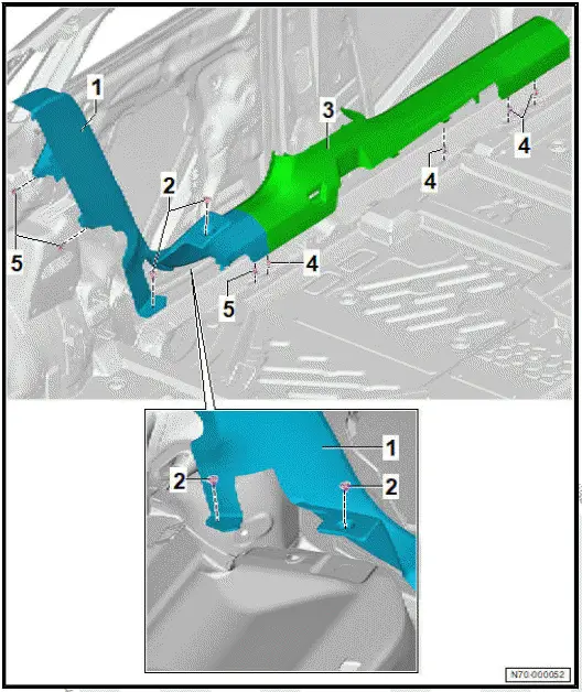
- Rear sill panel moulding
- ⇒ Rep. gr. 70 ; Removing and installing rear sill panel moulding
- Plug
- Qty. 2
- Front sill panel moulding
- ⇒ Rep. gr. 70 ; Removing and installing front sill panel moulding
- Retaining clip
- Qty. 4
- Retaining clip
- Qty. 3
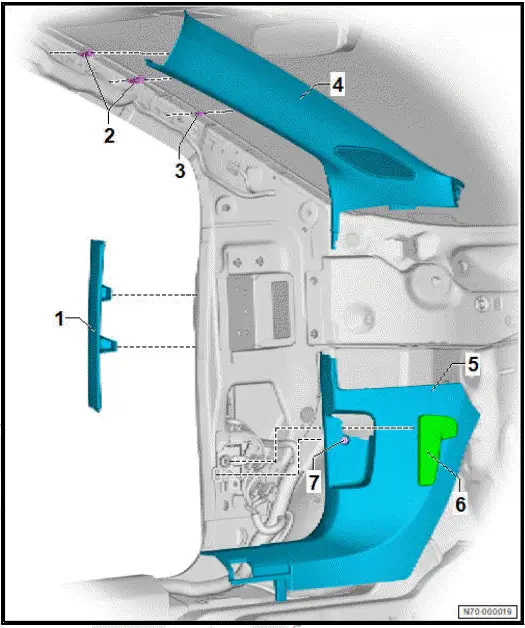
Assembly overview - A-pillar trim
Overview is shown for left side of vehicle as an example
- A-pillar gap cover
- Depending on equipment/ installation period
- Clip
- With barb
- Qty. 2
- Renew after removing
- Clip
- Upper A-pillar trim
- Renew after removing
- ⇒ "6.9 Removing and installing upper A-pillar trim"
- Lower A-pillar trim
- ⇒ "6.10 Removing and installing lower A-pillar trim"
- Bonnet lock operating lever
- ⇒ General body repairs, exterior; Rep.
gr. 55 ; Bonnet; Removing and installing bonnet lock release lever
- Clip
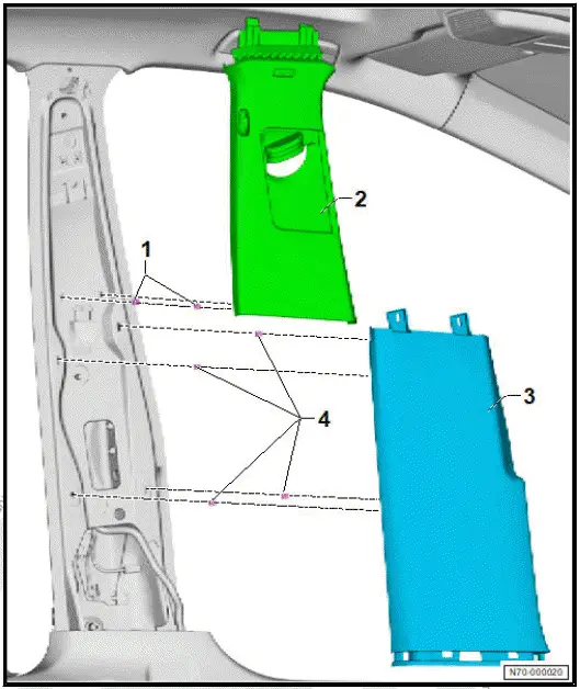
Assembly overview - B-pillar trim
Overview shown for left side of vehicle as an example
- Clip
- Qty. 2
- Upper part of B-pillar trim
- ⇒ Rep. gr. 70 ; Removing and installing upper B-pillar trim
- Lower B-pillar trim
- ⇒ Rep. gr. 70 ; Removing and installing lower B-pillar trim
- Clip
- Qty. 4
Assembly overview - C-pillar trim
The overview is shown for the left side of vehicle as an example.
- C-pillar trim
- ⇒ Rep. gr. 70 ; Removing and installing C-pillar trim
- Guide
- Clip
- Renew after removing
- Clip
- qty. 3

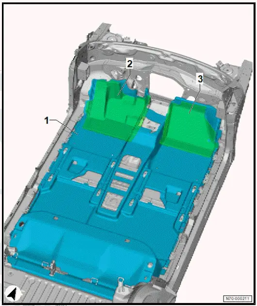
Assembly overview - foot rest and floor covering
The overview shows a left-hand drive vehicle as an example.
- Floor covering
- ⇒ Rep. gr. 70 ; Removing and installing floor covering
- Filler piece, driver side
- Filler piece, front passenger side
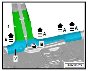
Removing and installing front sill panel moulding
Special tools and workshop equipment required
- release tool - T40280-
Removal and installation are described for the left side of vehicle as an example.
For a better view, the left front seat is not shown.
Removing
- Unclip front sill panel moulding -2- in direction of -arrow Ausing commercially available plastic wedge.
- Use commercially available plastic wedge to unclip front sill panel moulding -2- in direction of -arrow B- from lower B-pillar trim -1-.
Installing
Install in reverse order of removal, observing the following:
- Use release tool - T40280- to remove any retaining clips left in body, and insert them into front sill panel moulding for installation.
- Following installation, make sure that the front sill panel moulding is positioned in the inner door seal beading.
Removing and installing rear sill panel moulding
Special tools and workshop equipment required
- release tool - T40280-
- removal lever - 80-200-
Removal and installation are described for the left side of vehicle as an example.
Removing
- Remove bench seat ⇒ Rep. gr. 72 ; Removing and installing bench seat/individual seats .
- Remove front sill panel moulding ⇒ "6.7 Removing and installing front sill panel moulding"
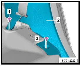
- Remove plugs -1- and -3- from rear sill panel moulding -2- using removal lever - 80-200- .
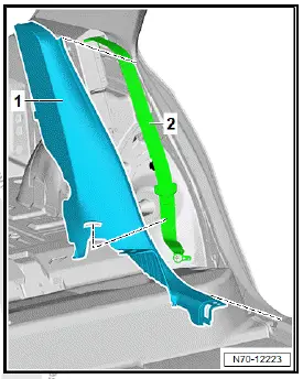
- Release rear sill panel moulding -1- using commercially available plastic wedge.
- Guide rear three-point seat belt -2- out of rear sill panel moulding -1-.
Installing
Install in reverse order of removal, observing the following:
- Use release tool - T40280- to remove any retaining clips left in body, and insert them into rear sill panel moulding for installation.
- Following installation, ensure that the rear sill panel moulding is positioned in the inner door seal beading.
Removing and installing upper A-pillar trim
NOTICE
Risk of damage to the curtain airbag due to incorrect removal.
- Do not use sharp objects when removing the A-pillar trim.
Removal and installation are described for the left side of vehicle as an example.
Removing
Remove A-pillar gap cover ⇒ Rep. gr. 70 ; Removing and installing A-pillar gap cover .
- Use a commercially available plastic wedge to detach upper A-pillar trim -1- from tab on moulded headliner -2- in direction of -arrow A-.
- Pull upper A-pillar trim -1- in area of clips with barbs -3- in direction of -arrow B- until stop of clips has been attained.
- Unclip upper A-pillar trim -1- in area of clip -4-.
- Push clips with barbs -3- in direction of -arrow C- out of upper A-pillar trim -1- .
- Remove upper A-pillar trim -1-.
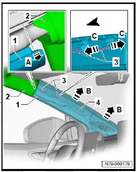
- Disconnect electrical connector
Installing
Install in reverse order of removal, observing the following:
- Insert clips with barbs -2- and clip -3- in direction of -arrowinto A-pillar trim -1-.
- Press on upper A-pillar trim -1- firmly.

- Following installation, ensure that upper A-pillar trim is positioned in inner door seal beading.
Removing and installing lower A-pillar trim
Special tools and workshop equipment required
- removal tool - T40280-
Removal and installation are described for the left side of vehicle as an example.
Removing
Vehicles with one-piece sill panel moulding
- Release sill panel moulding in area of lower A-pillar trim ⇒ Rep. gr. 70 ; Removing and installing front sill panel moulding .
All vehicles (continued)
- Remove A-pillar gap cover ⇒ Rep. gr. 70 ; Removing and installing A-pillar gap cover .
Driver side
- Remove bonnet lock release lever ⇒ General body repairs, exterior; Rep. gr. 55 ; Bonnet; Removing and installing bonnet lock release lever .
All vehicles (continued)
- Remove clip -2-.
- Free off lower A-pillar trim -1- in area of inner door seal.
- Use commercially available plastic wedge to unclip lower A-pillar trim -1- in direction of -arrow A-.
- Remove lower A-pillar trim -1- in direction of -arrow B-.
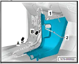
Installing
Install in reverse order of removal, observing the following:
- Remove any retaining clips left in body using removal tool - T40280- , and insert them into lower A-pillar trim for installation.
- Following installation, ensure that lower A-pillar trim is positioned in inner door seal beading.
Removing and installing A-pillar gap cover
Removal and installation are described for left side of vehicle as an example.
Removing
- Remove dash panel end cover ⇒ Rep. gr. 70 ; Removing and installing dash panel end cover .
- Free off A-pillar gap cover -1- in area of inner door seal.
- Using commercially available plastic wedge, unclip A-pillar gap cover -1- in direction of -arrow-, and remove it.
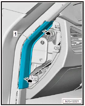
Installing
Install in reverse order of removal, observing the following:
- Make sure that upper A-pillar gap cover sits in beading of inner door seal following installation.
Removing and installing upper B-pillar trim
Special tools and workshop equipment required
- removal tool - T40280-
Removal and installation are described for left side of vehicle as an example.
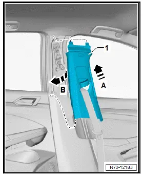
- Free off upper B-pillar trim -1- in area of inner door seal.
- Use commercially available plastic wedge to unclip lower B-pillar trim -1- at sides in direction of -arrow A-.
- Remove upper B-pillar trim -1- in direction of -arrow B-.
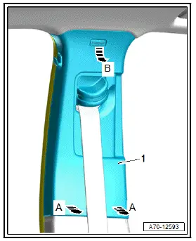
- Remove front belt end fitting ⇒ Rep. gr. 69 ; Removing and installing front belt end fitting .
- Guide front seat belt with belt end fitting out of upper B-pillar trim.
Installing
Install in reverse order of removal, observing the following:
- Remove any retaining clips left in body using removal tool - T40280- , and insert them into upper B-pillar trim for installation.
- Insert front belt end fitting through upper B-pillar trim -1-.
- Position upper B-pillar trim -1- at a slight angle, and insert it in direction of -arrow A-.
- Engage upper B-pillar trim -1- by swivelling it in direction of -arrow B-.
- Make sure that belt height adjuster functions correctly.
- Following installation, ensure that upper B-pillar trim is positioned in inner door seal beading.
Removing and installing lower B-pillar trim
Special tools and workshop equipment required
- removal lever - 80-200-
- removal tool - T40280-
Removal and installation are described for the left side of vehicle as an example.
Removing
- Release upper B-pillar trim ⇒ Rep. gr. 70 ; Removing and installing upper B-pillar trim .
Vehicles with one-piece sill panel moulding
- Release front sill panel moulding in area of lower B-pillar trim ⇒ General body repairs, interior; Rep. gr. 70 ; Trims, interior; Removing and installing front sill panel moulding .
All vehicles (continued)
Vehicles with two-piece sill panel moulding
- Release sill panel moulding in area of lower B-pillar trim ⇒ Rep. gr. 70 ; Removing and installing front sill panel moulding .
All vehicles (continued)
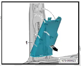
- Starting at bottom, unclip lower B-pillar trim -1- in direction of -arrow- using removal lever - 80-200- , and remove it.
Installing
Install in reverse order of removal, observing the following:
- Remove any retaining clips left in body using removal tool - T40280- , and insert them into lower B-pillar trim for installation.
- Renew any damaged fasteners.
- Following installation, ensure that lower B-pillar trim is positioned in inner door seal beading.
Removing and installing C-pillar trim
Special tools and workshop equipment required
- removal tool - T40280-
Removal and installation are described for left side of vehicle as an example.
Removing
- Remove rear shelf.
- Release rear sill panel moulding in upper area ⇒ "6.8 Removing and installing rear sill panel moulding"
- Release luggage compartment side trim in area of C-pillar ⇒ Rep. gr. 70 ; Removing and installing luggage compartment side trim .
- Fold rear seat backrest towards front.
- Free off C-pillar trim -1- in area of inner door seal and rear lid seal.
- Using commercially available plastic wedge, unclip C-pillar trim -1- in direction of -arrow-, and remove it.

Installing
Install in reverse order of removal, observing the following:
- Remove any retaining clips left in body using removal tool - T40280- , and insert them into C-pillar trim for installation.
- Following installation, make sure that the C-pillar trim is positioned in the beading of the inner door seal and rear lid seal.
Removing and installing floor covering
Removing
- Remove variable luggage compartment floor.
- Remove front seats ⇒ Rep. gr. 72 ; Removing and installing front seat .
- Remove rear sill panel mouldings ⇒ Rep. gr. 70 ; Removing and installing rear sill panel moulding .
- Remove lower A-pillar trims ⇒ Rep. gr. 70 ; Removing and installing lower A-pillar trim .
- Remove tunnel support cover ⇒ Rep. gr. 70 ; Removing and installing tunnel support cover .
- Remove foot mats.
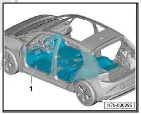
- Lift floor covering -1- and guide out wiring harnesses.
NOTICE
Risk of damage to floor covering caused by tearing at cutouts.
- Proceed very carefully when folding the floor covering.
- Remove floor covering.
Installing
Install in reverse order of removal, observing the following:
- Make sure that condensation drain is not compressed.
Removing and installing foot rest
Removal and installation are described for the driver side of a left-hand drive vehicle as an example.
Removing
- Detach floor covering in area of foot rest ⇒ Rep. gr. 70 ; Removing and installing floor covering .
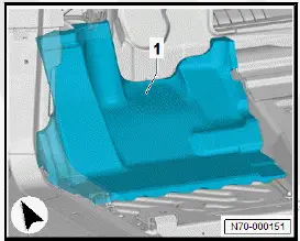
- Remove foot rest -1-.
Installing
Install in reverse order of removal, observing the following:
- Ensure that condensation drain is positioned correctly.