Ecu Diagnosis Information - Combination Meter ++
Values On The Diagnosis Tool
| Monitor Item | Condition | Value/Status | |
|---|---|---|---|
SPEED METER [mph or km/h] |
Ignition switch ON | While driving | Input value of Nissan Pathfinder vehicle speed signal (CAN communication signal) |
SPEED OUTPUT [mph or km/h] |
Ignition switch ON | While driving | Output value of Nissan Pathfinder vehicle speed signal (CAN communication signal) |
ODO OUTPUT [mph or km/h] |
Ignition switch ON | — | Output value of odometer signal (CAN communication signal) |
TACHO METER [rpm] |
Ignition switch ON | Engine running | Input value of engine speed signal (CAN communication signal) |
FUEL METER [L] |
Ignition switch ON | — | Input value of fuel level sensor signal |
W TEMP METER [°F or °C] |
Ignition switch ON | — | Input value of engine coolant temperature signal (CAN communication signal) |
| ABS W/L | Ignition switch ON | ABS warning lamp: ON | On |
| Other than the above | Off | ||
| VDC/TCS IND | Ignition switch ON | VDC OFF indicator lamp: ON | On |
| Other than the above | Off | ||
| SLIP IND | Ignition switch ON | VDC warning lamp: ON | On |
| Other than the above | Off | ||
| BRAKE W/L | Ignition switch ON | Brake warning lamp: ON | On |
| Other than the above | Off | ||
| E-PKB warning lamp | Ignition switch ON | Electric parking brake warning lamp: ON | On |
| Other than the above | Off | ||
| DOOR W/L | Ignition switch ON | During door open warning indication | On |
| Other than the above | Off | ||
| TRUNK/GLAS-H | Ignition switch ON | Off | |
| HI-BEAM IND | Ignition switch ON | High beam indicator lamp: ON | On |
| Other than the above | Off | ||
| TURN IND | Ignition switch ON | Turn signal indicator lamp: ON | On |
| Other than the above | Off | ||
| FR FOG IND | Ignition switch ON | Front fog lamp indicator lamp: ON | On |
| Other than the above | Off | ||
| RR FOG IND | Ignition switch ON | Off | |
| LIGHT IND | Ignition switch ON | Position lamp indicator lamp: ON | On |
| Other than the above | Off | ||
| OIL W/L | Ignition switch ON | During engine oil pressure warning lamp ON | On |
| Except during engine oil pressure warning lamp OFF | Off | ||
| MIL | Ignition switch ON | Malfunction indicator lamp (yellow) ON | On |
| Malfunction indicator lamp (yellow) OFF | Off | ||
| GLOW IND | Ignition switch ON | Off | |
| C-ENG2 W/L | Ignition switch ON | Off | |
| CRUISE IND | Ignition switch ON | Off | |
| SET IND | Ignition switch ON | Off | |
| CRUISE W/L | Ignition switch ON | Off | |
| BA W/L | Ignition switch ON | AEB warning lamp: ON | On |
| Other than the above | Off | ||
| ATC/T-AMT W/L | Ignition switch ON | Off | |
ATF TEMP W/L [Off] |
Ignition switch ON | Off | |
| CVT IND | Ignition switch ON | Off | |
| 4WD W/L | Ignition switch ON | Off | |
| FUEL W/L | Ignition switch ON | During low fuel warning indication | On |
| Other than the above | Off | ||
| WASHER W/L | Ignition switch ON | During low washer fluid warning indication | On |
| Other than the above | Off | ||
| AIR PRES W/L | Ignition switch ON | Low tire pressure warning lamp ON | On |
| Other than the above | Off | ||
| KEY G/Y W/L | Ignition switch ON | During Intelligent Key system malfunction indication | On |
| Except during Intelligent Key system malfunction indication | Off | ||
| KEY R W/L | Ignition switch ON | During Intelligent Key system malfunction indication | On |
| Except during Intelligent Key system malfunction indication | Off | ||
| KEY KNOB W/L | Ignition switch ON | During Intelligent Key system malfunction indication | On |
| Except during Intelligent Key system malfunction indication | Off | ||
| EPS W/L | Ignition switch ON | Power steering warning lamp ON | On |
| Other than the above | Off | ||
| e-4WD W/L | Ignition switch ON | Off | |
| AFS OFF IND | Ignition switch ON | Off | |
| 4WAS/RAS W/L | Ignition switch ON | Off | |
| DDS W/L | Ignition switch ON | Off | |
| LANE W/L | Ignition switch ON | Off | |
| LDP IND | Ignition switch ON | Off | |
| SLOW IND | Ignition switch ON | Off | |
| READY IND | Ignition switch ON | Off | |
| INVT TEMP IND | Ignition switch ON | Off | |
| SYS FAIL W/L | Ignition switch ON | Off | |
| HV BAT W/L | Ignition switch ON | Off | |
| HEV BRAKE W/L | Ignition switch ON | Off | |
| SFT OPER W/L | Ignition switch ON | Off | |
| LANE KEEP W/L | Ignition switch ON | Off | |
| IDOL STOP IND | Ignition switch ON | Off | |
| CHAGE W/L | Ignition switch ON | 12V battery charge warning lamp ON | On |
| Other than the above | Off | ||
| 4WD AUTO IND | Ignition switch ON | Off | |
| DPF W/L | Ignition switch ON | Off | |
| TRAILER IND | Ignition switch ON | Off | |
| ECO MODE IND | Ignition switch ON | ECO drive indicator lamp ON | On |
| Other than the above | Off | ||
| ATP W/L | Ignition switch ON | Off | |
| E-SUS IND | Ignition switch ON | Off | |
| DCA IND | Ignition switch ON | Off | |
| MT SYNC REV IND | Ignition switch ON | Off | |
| FILTER W/L | Ignition switch ON | Off | |
| Urea remaining W/L | Ignition switch ON | Off | |
| ACC TARGET | Ignition switch ON | During Nissan Pathfinder vehicle ahead detection indicator is displayed | On |
| During Nissan Pathfinder vehicle ahead detection indicator is not displayed | Off | ||
| ACC DISTANCE | Ignition switch ON | Set distance indicator (short) is displayed | SHORT |
| Set distance indicator (mid) is displayed | Mid | ||
| Set distance indicator (long) is displayed | LONG | ||
| During set distance indicator not displayed | Off | ||
| ACC SET SPEED | Ignition switch ON | During set Nissan Pathfinder vehicle speed indicator not displayed | Off |
| During set Nissan Pathfinder vehicle speed indicator displayed | Indicates the set vehicle speed | ||
| ACC UNIT | Ignition switch ON | Set Nissan Pathfinder vehicle speed indicator unit display ON | On |
| Set Nissan Pathfinder vehicle speed indicator unit display OFF | Off | ||
| SHIFT IND | Ignition switch ON | — | Indicates the shift position |
| GEAR SHIFT IND | Ignition switch ON | Off | |
| 4WD IND | Ignition switch ON | Off | |
| OFFLOAD IND | Ignition switch ON | Off | |
| ECO DRIVE IND G | Ignition switch ON | Off | |
| ECO DRIVE IND O | Ignition switch ON | Off | |
| BSW IND | Ignition switch ON | Off | |
| DRIVE MODE STATS | Ignition switch ON | Off | |
| SCR/OIL DISP | Ignition switch ON | Off | |
| TOW MODE IND | Ignition switch ON | Off | |
| CHECK SUS IND | Ignition switch ON | Off | |
| FUEL CAP W/L | Ignition switch ON | During fuel filler cap warning indication | On |
| Other than the above | Off | ||
| E-PKB indicator | Ignition switch ON | Electric parking brake indicator lamp ON | On |
| Other than the above | Off | ||
| PNP P SW | Ignition switch ON | Off | |
| PNP N SW | Ignition switch ON | Off | |
| O/D OFF SW | Ignition switch ON | SPORT mode switch ON | On |
| Other than the above | Off | ||
| RANGE 1 | Ignition switch ON | Off | |
| AT S MODE SW | Ignition switch ON | Off | |
| AT P MODE SW | Ignition switch ON | Off | |
| M RANGE SW | Ignition switch ON | Off | |
| NM RANGE SW | Ignition switch ON | Off | |
| AT SFT UP SW | Ignition switch ON | Off | |
| AT SFT DWN SW | Ignition switch ON | Off | |
| ST SFT UP SW | Ignition switch ON | Off | |
| ST SFT DWN SW | Ignition switch ON | Off | |
| AIR COND SIG | Ignition switch ON | Off | |
| HEATER FAN SW | Ignition switch ON | Off | |
| REAR DEF SW | Ignition switch ON | Off | |
| A/C LOW TEMP | Ignition switch ON | Off | |
| COMP F/B SIG | Ignition switch ON | Off | |
| 4WD LOCK SW | Ignition switch ON | Off | |
| SYNC MODE | Ignition switch ON | Off | |
| PKB SW | Ignition switch ON | Parking brake switch ON (except electric parking brake system) | On |
| Parking brake switch OFF (except electric parking brake system) | Off | ||
| BUCKLE SW | Ignition switch ON | Driver seat belt not fastened | On |
| Driver seat belt fastened | Off | ||
| BRAKE OIL SW | Ignition switch ON | Brake fluid level switch ON | On |
| Other than the above | Off | ||
| AIR BAG SIG | Ignition switch ON | SRS air bag warning lamp signal is received | On |
| Other than the above | Off | ||
| CHG SIG | Ignition switch ON | 12V battery charge warning lamp signal is received | On |
| Other than the above | Off | ||
| RR COMB STATE | Ignition switch ON | Off | |
| ABS EXIST | Ignition switch ON | Off | |
| VDC/TCS EXIST | Ignition switch ON | Off | |
| AMB POWER | Ignition switch ON | Off | |
| MODE A SW | Ignition switch ON | Off | |
| MODE B SW | Ignition switch ON | Off | |
| MT SYNC REV SW | Ignition switch ON | Off | |
| PASS BUCKLE SW | Ignition switch ON |
|
On |
|
Off | ||
| TOW MODE SW | Ignition switch ON | Off | |
| ECO MODE SW | Ignition switch ON | ECO mode switch ON | On |
| Other than the above | Off | ||
| SPORT MODE SW | Ignition switch ON | SPORT mode switch ON | On |
| Other than the above | Off | ||
| Electric shift W/L (red) | Ignition switch ON | Electric shift warning lamp (red): ON | On |
| Other than the above | Off | ||
| LED LMP R OPEN | Ignition switch ON | Front combination lamp RH malfunction | On |
| Other than the above | Off | ||
| LED LMP L OPEN | Ignition switch ON | Front combination lamp LH malfunction | On |
| Other than the above | Off | ||
DISTANCE [km] |
Ignition switch ON | — | Distance to empty |
OUTSIDE TEMP [°F or °C] |
Ignition switch ON | — | Displays the ambient air temperature which is input from the ambient sensor. |
| FUEL LOW SIG | Ignition switch ON | Low fuel warning: ON | On |
| Other than the above | Off | ||
| CRANKING SIG | Ignition switch ON | When engine is cranking | On |
| Other than the above | Off | ||
| ST CNT SIG | Ignition switch ON | When starter control status signal is received from BCM via CAN communication. | On |
| Other than the above | Off | ||
| DOOR LOCK SIG | Ignition switch ON | Door lock signal: ON | On |
| Other than the above | Off | ||
| DR DOOR SIG | Ignition switch ON | — | LHD |
| BUZZER | Ignition switch ON | Buzzer ON | On |
| Buzzer OFF | Off | ||
| BATTERY CIRCUIT STATUS | — | Shipping mode ON | On |
| Other than shipping mode | Off | ||
| PARKING ASSIST DSP | Ignition switch ON | Sonar display setting ON | On |
| Sonar display setting OFF | Off | ||
| PARKING ASSIST SENSOR | Ignition switch ON | When sonar set to "OFF" | Off |
| When sonar set to "Rear" | Rear | ||
| When sonar set to "Front" | FRONT | ||
| When sonar set to "ON" | On | ||
| Other than above | Not support | ||
| PARKING ASSIST VOLUME | Ignition switch ON | When sonar volume set to "HIGH" | HIGH |
| When sonar volume set to "MIDDLE" | MEDIUM | ||
| When sonar volume set to "LOW" | LOW | ||
| Other than above | Not support | ||
| PARKING ASSIST RANGE | Ignition switch ON | When sonar range set to "NEAR" | NEAR |
| When sonar range set to "MEDIUM" | MEDIUM | ||
| When sonar range set to "FAR" | FAR | ||
| Other than above | Not support | ||
| RAB W/L | Ignition switch ON | RAB warning lamp: ON | On |
| Other than the above | Off | ||
| Electric shift W/L | Ignition switch ON | Electric shift warning lamp: ON | On |
| Other than the above | Off | ||
| Sailing stop W/L | Ignition switch ON | Off | |
| ALL PWER MTER | Ignition switch ON | kw | |
| SOC METER | Ignition switch ON | % | |
| VOLTMETER | Ignition switch ON | V | |
| BRAKE PAD W/L | Ignition switch ON | V | |
| TPMS DISP | Ignition switch ON | TPMS display: ON | On |
| Other than the above | Off | ||
| TIRE STATUS FR | Ignition switch ON | Off | |
| TIRE STATUS FL | Ignition switch ON | Off | |
| TIRE STATUS RR | Ignition switch ON | Off | |
| TIRE STATUS RL | Ignition switch ON | Off | |
| SONAR SET AVA | Ignition switch ON | During the setting of the combination meter | Available |
| Other than the above | Unavailable | ||
| STRG SW INPUT | Ignition switch ON | Control switch is pressed | SW1 |
| Scroll dial is rotated upward | SW2 | ||
| Scroll dial is rotated downward | SW3 | ||
| OK switch is pressed | SW4 | ||
| LEFT/BACK switch is pressed | SW5 | ||
| RIGHT switch is pressed | SW6 | ||
| VOLUME DOWN switch is pressed | SW7 | ||
| VOLUME UP switch is pressed | SW8 | ||
| TEL switch is pressed | SW9 | ||
| VR switch is pressed | SW10 | ||
| SEEK DOWN switch is pressed | SW11 | ||
| SEEK UP switch is pressed | SW12 | ||
| Other than above | NO INPUT | ||
| STRG SW OUTPUT | Ignition switch ON | Control switch is pressed | SW1 |
| Scroll dial is rotated upward | SW2 | ||
| Scroll dial is rotated downward | SW3 | ||
| OK switch is pressed | SW4 | ||
| LEFT/BACK switch is pressed | SW5 | ||
| RIGHT switch is pressed | SW6 | ||
| VOLUME DOWN switch is pressed | SW7 | ||
| VOLUME UP switch is pressed | SW8 | ||
| TEL switch is pressed | SW9 | ||
| VR switch is pressed | SW10 | ||
| SEEK DOWN switch is pressed | SW11 | ||
| SEEK UP switch is pressed | SW12 | ||
| Other than above | NO OUTPUT | ||
| ITS SONAR SET OUTPUT | Ignition switch ON | LDW status in combination meter selection ON | LDW On |
| LDW status in combination meter selection OFF | LDW Off | ||
| BSW status in combination meter selection ON | BSW On | ||
| BSW status in combination meter selection OFF | BSW Off | ||
| AEB status in combination meter selection ON | FEB On | ||
| AEB status in combination meter selection OFF | FEB Off | ||
| MOD setting: ON | P MV ON | ||
| MOD setting: OFF | P MV OFF | ||
| Sonar display setting: ON | SONAR ON | ||
| Sonar display setting: ON | SONAR OFF | ||
| Sonar sensor setting: ON | P SEN ON | ||
| Sonar sensor setting: OFF | P SEN OFF | ||
| Sonar sensor setting: FRONT | P SEN FRONT | ||
| Sonar volume setting: HIGH | P BUZ HIGH | ||
| Sonar volume setting: MED | P BUZ MED | ||
| Sonar volume setting: LOW | P BUZ LOW | ||
| Sonar distance setting: FAR | P RNG FAR | ||
| Sonar distance setting: MED | P RNG MED | ||
| Sonar distance setting: NEAR | P RNG NEAR | ||
| Other than above | NO SW ST | ||
| HI-BEAM ASST IND | Ignition switch ON | High beam assist indicator lamp ON | On |
| High beam assist indicator lamp OFF | Off | ||
| AVM display | Ignition switch ON | Off | |
| SONAR DET STATUS | Ignition switch ON | Sonar control unit detected the obstacle | On |
| Sonar control unit not detected the obstacle | Off | ||
| SONAR WARN | Ignition switch ON | Sonar sensor error ON (sonar system ON) | ERROR |
| Sonar system OFF | DEACT | ||
| Sonar sensor error OFF (sonar system ON) | Off | ||
| SONAR DET DSP RC | Ignition switch ON | Level of distance from center sensor rear to obstacle level1 | LEVEL1 |
| Level of distance from center sensor rear to obstacle level2 | LEVEL2 | ||
| Level of distance from center sensor rear to obstacle level3 | LEVEL3 | ||
| Level of distance from center sensor rear to obstacle level4 | LEVEL4 | ||
| SONAR DET DSP AREA RC | Ignition switch ON | Obstacle is within the warning area of center sensor rear | On |
| Other than above | Off | ||
| DIPPED BEAM IND | Ignition switch ON | Off | |
| SONAR DET DSP RL | Ignition switch ON | Level of distance from corner sensor rear LH to obstacle level1 | LEVEL1 |
| Level of distance from corner sensor rear LH to obstacle level2 | LEVEL2 | ||
| Level of distance from corner sensor rear LH to obstacle level3 | LEVEL3 | ||
| Level of distance from corner sensor rear LH to obstacle level4 | LEVEL4 | ||
| SONAR DET DSP AREA RL | Ignition switch ON | Obstacle is within the warning area of corner sensor rear LH | On |
| Other than above | Off | ||
| SONAR DET DSP RR | Ignition switch ON | Level of distance from corner sensor rear RH to obstacle level1 | LEVEL1 |
| Level of distance from corner sensor rear RH to obstacle level2 | LEVEL2 | ||
| Level of distance from corner sensor rear RH to obstacle level3 | LEVEL3 | ||
| Level of distance from corner sensor rear RH to obstacle level4 | LEVEL4 | ||
| SONAR DET DSP AREA RR | Ignition switch ON | Obstacle is within the warning area of corner sensor rear RH | On |
| Other than above | Off | ||
| SONAR DET DSP FC | Ignition switch ON | Level of distance from center sensor front to obstacle level1 | LEVEL1 |
| Level of distance from center sensor front to obstacle level2 | LEVEL2 | ||
| Level of distance from center sensor front to obstacle level3 | LEVEL3 | ||
| Level of distance from center sensor front to obstacle level4 | LEVEL4 | ||
| SONAR DET DSP AREA FC | Ignition switch ON | Obstacle is within the warning area of center sensor front | On |
| Other than above | Off | ||
| SONAR DET DSP FL | Ignition switch ON |
Level of distance from corner sensor front LH to obstacle level 1 | LEVEL1 |
| Level of distance from corner sensor front LH to obstacle level 2 | LEVEL2 | ||
| Level of distance from corner sensor front LH to obstacle level 3 | LEVEL3 | ||
| Level of distance from corner sensor front LH to obstacle level 4 | LEVEL4 | ||
| SONAR DET DSP AREA FL | Ignition switch ON | Obstacle is within the warning area of corner sensor front LH | On |
| Other than above | Off | ||
| SONAR DET DSP FR | Ignition switch ON | Level of distance from corner sensor front RH to obstacle level 1 | LEVEL1 |
| Level of distance from corner sensor front RH to obstacle level 2 | LEVEL2 | ||
| Level of distance from corner sensor front RH to obstacle level 3 | LEVEL3 | ||
| Level of distance from corner sensor front RH to obstacle level 4 | LEVEL4 | ||
| SONAR DET DSP AREA FR | Ignition switch ON | Obstacle is within the warning area of corner sensor front RH | On |
| Other than above | Off | ||
| SONAR DIST DSP | Ignition switch ON | Distance from obstacle to corner sensor is less than 30 cm | STOP |
| Distance from obstacle to corner sensor is 30 cm or more and less than 40 cm | 30 cm | ||
| Distance from obstacle to corner sensor is 40 cm or more and less than 50 cm | 40 cm | ||
| Distance from obstacle to corner sensor is 50 cm or more and less than 60 cm | 50 cm | ||
| Distance from obstacle to corner sensor is 60 cm or more and less than 70 cm | 60 cm | ||
| Distance from obstacle to corner sensor is more than 70 cm | Off | ||
| Engine Off timer | Ignition switch ON | 0 | |
| TRQ DSTRBT | Ignition switch ON | % | |
| LANE IND | Ignition switch ON | LANE display: ON | On |
| LANE display: blink | BLINK | ||
| LANE display: OFF | Off | ||
| FCW IND | Ignition switch ON | FCW system: ON | On |
| FCW system: blink | BLINK | ||
| FCW system: OFF | Off | ||
| LDW IND | Ignition switch ON | LDW system: ON | On |
| LDW system: blink | BLINK | ||
| LDW system: OFF | Off | ||
| TPMS FLT TIRE | Ignition switch ON | Flat tire | On |
| Other than above | Off | ||
| TPMS PRESS L | Ignition switch ON | Tire pressure is low | On |
| Tire pressure is normal | Off | ||
| 4WD CL TMP H | Ignition switch ON | Off | |
| 4WD TIRE CHCK | Ignition switch ON | Off | |
| 4WD SYS MALF | Ignition switch ON | Off | |
| E SUS MALF | Ignition switch ON | Off | |
| ABS MALF | Ignition switch ON | ABS malfunction display: ON | On |
| Other than above | Off | ||
| VDC MALF | Ignition switch ON | VDC malfunction display: ON | On |
| Other than above | Off | ||
| ENG SYS CHCK | Ignition switch ON | Engine warning display: ON | On |
| Other than above | Off | ||
| ASCD SYS MALF | Ignition switch ON | ASCD malfunction display: ON | On |
| Other than above | Off | ||
| OVER-BOOST IND | Ignition switch ON | Off | |
| ASCD SPD BLNK | Ignition switch ON | Set Nissan Pathfinder vehicle speed indicator blinking | On |
| Set vehicle speed indicator not blinking | Off | ||
| ASCD STATUS | Ignition switch ON | ASCD system OFF | Off |
| ASCD system ON | ASCD | ||
| ASCD set Nissan Pathfinder vehicle speed | CRUISE | ||
| ASCD REQ SPD | Ignition switch ON | While driving | Same value as ASCD or speed limiter set Nissan Pathfinder vehicle speed |
| Urea remain | Ignition switch ON | Off | |
| E/O CHG TMNG | Ignition switch ON | 0 | |
| E/O CHG TMNG RST | Ignition switch ON | Resetting of a remaining distance to the engine oil change time. | On |
| Other than above | Off | ||
| Urea time | Ignition switch ON | 0 | |
| AT STOP START IND | Ignition switch ON | Off | |
| AT STOP START STS | Ignition switch ON | Off | |
| AT STOP START SW | Ignition switch ON | Off | |
| HILL HOLD WARNING | Ignition switch ON | Off | |
| ASSIST/CHARGE GAUGE | Ignition switch ON | % | |
| ACCEL GAUGE | Ignition switch ON | % | |
| ECO ACCEL POSITION | Ignition switch ON | — | Value of ECO pedal guide display |
| REGENERATIVE BRAKE TRQ | Ignition switch ON | % | |
| MECHANICAL BRAKE TRQ | Ignition switch ON | % | |
| ENERGY FLOW | Ignition switch ON | MODE8 | |
| ECO DRIVE NAVI | Ignition switch ON | — | LEVEL 0 - LEVEL 30 |
| Target front Nissan Pathfinder vehicle | Ignition switch ON | Target front Nissan Pathfinder vehicle display: ON | On |
| Target front Nissan Pathfinder vehicle display: BLINK | BLINK | ||
| Target front Nissan Pathfinder vehicle display: IBA BLINK | IBA BLINK | ||
| Other than above | Off | ||
| BCI | Ignition switch ON | Off | |
| BCI LEFT | Ignition switch ON | Off | |
| BCI RIGHT | Ignition switch ON | Off | |
| CRUISE READY IND | Ignition switch ON | Off | |
| Set Forward Emergency Brake | Ignition switch ON | FEB setting is ON | On |
| FEB setting is OFF | Off | ||
| FEB is not available. | Not support | ||
| SET LDW | Ignition switch ON | LDW setting is ON | On |
| LDW setting is OFF | Off | ||
| LDW is not available. | Not support | ||
| SET BSW | Ignition switch ON | BSW setting is ON | On |
| BSW setting is OFF | Off | ||
| BSW is not available. | Not support | ||
| Set Lane timing | Ignition switch ON | Off | |
| SET BCI BRAKE RESUME | Ignition switch ON | Off | |
| SET DCA | Ignition switch ON | Off | |
| SET LDP | Ignition switch ON | LDP setting is ON | On |
| LDP setting is OFF | Off | ||
| LDP is not available. | Not support | ||
| SET DCA TIMING | Ignition switch ON | Off | |
| SET RMOD | Ignition switch ON | Off | |
| SET BCI IGNITION STATUS | Ignition switch ON | Off | |
| SET IBA | Ignition switch ON | Not support | |
| MSS RADER DEACTIVATED | Ignition switch ON | Off | |
| CHASSIS CONTROL WARN | Ignition switch ON | Chassis control display (warning) indication | On |
| Other than above | Off | ||
| Set Direct Adaptive Steering | Ignition switch ON | Off | |
| Set Emergency Assist Pedal | Ignition switch ON | EAPM setting is ON | On |
| EAPM setting is OFF | Off | ||
| EAPM is not available. | Not support | ||
| Set No Entry | Ignition switch ON | Not support | |
| Set Traffic Sign Recognition | Ignition switch ON | TSR setting is ON | On |
| TSR setting is OFF | Off | ||
| TSR is not available. | Not support | ||
| SIGNAL WARNING STATUS | Ignition switch ON | signal warning is ON | On |
| Other than above | Off | ||
| HEV system state | Ignition switch ON | Off | |
| LOW LI-ION BAT CHG WARN | Ignition switch ON | Off | |
| VSP OFF IND | Ignition switch ON | Off | |
| TIRE PRESS FR | Ignition switch ON | — | 0 - 63.75 |
| TIRE PRESS FL | Ignition switch ON | — | 0 - 63.75 |
| TIRE PRESS RR | Ignition switch ON | — | 0 - 63.75 |
| TIRE PRESS RL | Ignition switch ON | — | 0 - 63.75 |
| BSW IND | Ignition switch ON | BSW system display: ON | On |
| BSW system display: WARN ON | WARN ON | ||
| BSW system display: BLINK | BLINK | ||
| Other than above | Off | ||
| IBA IND | Ignition switch ON | Off | |
| DCA IND | Ignition switch ON | Off | |
| LDP IND | Ignition switch ON | I-LI system display ON | On |
| Other than above | Off | ||
| BSI IND | Ignition switch ON | I-BSI system display ON | On |
| Other than above | Off | ||
| STATUS CHECK DSP | Ignition switch ON | Off | |
| SET SPEED FLASHING | Ignition switch ON | Off | |
| MSS STATUS WARNING ERR | Ignition switch ON | Off | |
| MSS NO WARN SET | Ignition switch ON | Off | |
| MSS NO DYNAMIC SET | Ignition switch ON | Off | |
| PA display request | Ignition switch ON | Off | |
| Ack for PA | Ignition switch ON | Off | |
| Camera display request | Ignition switch ON | Off | |
| PA malfunction | Ignition switch ON | Off | |
| Steering SW output | Ignition switch ON | Off | |
| Status of call display | Ignition switch ON | ProPILOT Assist system display jump function: ON | On |
| ProPILOT Assist system display jump function: OFF | Off | ||
| Lane detect | Ignition switch ON | Lane detection: ON | On |
| Other than above | Off | ||
| PP inst message | Ignition switch ON | ProPILOT Assist system instruction message: Speed | Speed |
| ProPILOT Assist system instruction message: Active 1 | Active 1 | ||
| ProPILOT Assist system instruction message: Active 2 | Active 2 | ||
| ProPILOT Assist system instruction message: Standby | Standby | ||
| ProPILOT Assist system instruction message: No message | No msg | ||
| ProPILOT Assist system instruction message: OFF | Off | ||
| PP display status | Ignition switch ON | Stand-by display (white) ON | Stby |
| Stand-by display (white) blink | Stby P | ||
| Operation display (green) ON | Active | ||
| Operation display (green) blink | Active P | ||
| Steering assist alert display (red) ON | Free | ||
| Steering assist alert display (red) blink | Free H | ||
| PloPILOT system is malfunction | Malf | ||
| PloPILOT display OFF | Off | ||
| Hand free status | Ignition switch ON | Hands free warning display: ON | On |
| Other than above | Off | ||
| PP cancel info | Ignition switch ON | ProPILOT Assist system cancel information: Speed | Speed |
| ProPILOT Assist system cancel information: Target | Target | ||
| ProPILOT Assist system cancel information: PA | PA | ||
| ProPILOT Assist system cancel information: Obstacle | Obstacle | ||
| ProPILOT Assist system cancel information: Weather | Weather | ||
| ProPILOT Assist system cancel information: E-PKB | E-PKB | ||
| ProPILOT Assist system cancel information: Seatbelt | Seatbelt | ||
| ProPILOT Assist system cancel information: OFF | No act | ||
| FEB status | Ignition switch ON | AEB system function: ON | On |
| Other than above | Off | ||
| PP setting status | Ignition switch ON | ProPILOT Assist system function is not available. | Temp 1 |
| ProPILOT Assist system function is not available. | Temp 2 | ||
| ProPILOT Assist system function is available. | Avail 1 | ||
| ProPILOT Assist system function is available. | Avail 2 | ||
| Nissan Pathfinder Vehicle distance | Ignition switch ON | 0 | |
| EAPM status | Ignition switch ON | EAPM is ON | On |
| EAPM is OFF | Off | ||
| EAPM is not available. | No spprt | ||
| Traffic sign | Ignition switch ON | TSR display: Signal | Signal |
| TSR display: No entry | No entry | ||
| TSR display: Stop | stop | ||
| TSR display: No message | No msg | ||
Reference Value
TERMINAL LAYOUT

PHYSICAL VALUES
Terminal No. (Wire color) | Description | Condition | Value (Approx.) |
||||
|---|---|---|---|---|---|---|---|
| + | – | Signal name | Input/ Output |
||||
1 (R) |
Ground | Illumination control signal | Output | Ignition switch ON |
|
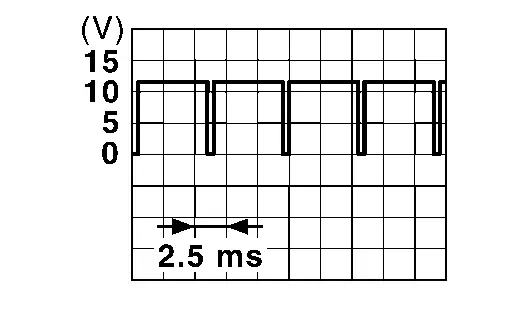 |
|
| — | Battery voltage | ||||||
|
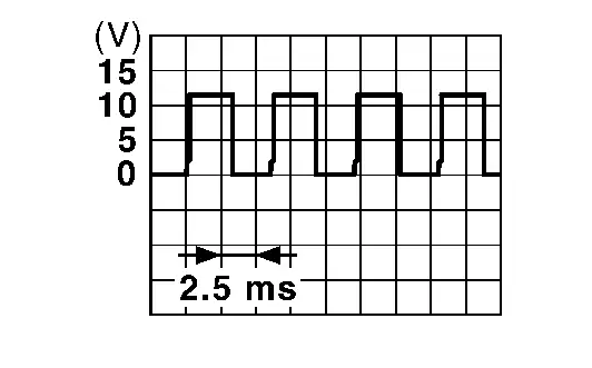 |
||||||
|
0 V | ||||||
3 (LA/G) |
Ground | Master speaker signal | Output | [Ignition switch ON]
|
Outputs waveform synchronized with sound. |  |
|
4 (LA/L) |
Ground | Master speaker ground | — | Ignition switch ON | — | — | |
5 (LA/W) |
Ground | Battery power supply | Input | Ignition switch OFF | — | Battery voltage | |
6 (LA/BG) |
Ground | Ignition signal | Input | Ignition switch ON | — | Battery voltage | |
7 (B) |
Ground | Ground | — | — | — | 0 V | |
12 (GR) |
Ground | Nissan Pathfinder Vehicle speed signal (8-pulse) |
Output | Ignition switch ON | Speedometer operated [When Nissan Pathfinder vehicle speed is approx. 40 km/h] |
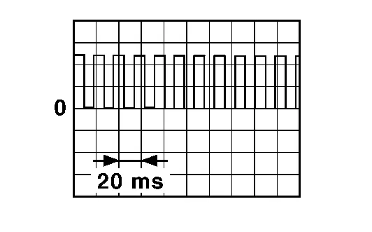 |
|
15 (P) |
Ground | Washer fluid level switch signal | Input | Ignition switch ON | Washer fluid level switch ON | 0 V | |
| Washer fluid level switch OFF | Battery voltage | ||||||
18 (L) |
Ground | CAN-High | — | — | — | — | |
19 (R) |
Ground | CAN-Low | — | — | — | — | |
23 (BG) |
Ground | Steering switch signal B | Input | Ignition switch ON | Keep pressing VOLUME DOWN switch | 0 V | |
| Keep pressing VOLUME UP switch | 0.3 V | ||||||
| Keep pressing TEL switch | 0.7 V | ||||||
| Keep pressing VR switch | 1.2 V | ||||||
| Keep pressing SEEK DOWN switch | 1.9 V | ||||||
| Keep pressing SEEK UP switch | 2.7 V | ||||||
| Other than the above | 3.3 V | ||||||
25 (BR) |
Ground | Illumination control switch signal (+) | Input | Ignition switch ON | Illumination control switch (+) is pressed | 0 V | |
| Other than the above | 3.3 V | ||||||
28 (G) |
Ground | Brake fluid level switch signal | Input | Ignition switch ON | Brake fluid level low | 5.0 V | |
| Brake fluid level normal | Battery voltage | ||||||
29 (P) |
Ground | Ambient sensor signal | Input | Ignition switch ON | Changes depending on ambient temperature. | 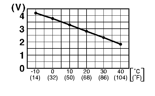 |
|
30 (LG) |
Ground | Ambient sensor ground | — | Ignition switch ON | — | 0 V | |
31 (Y) |
Ground | Illumination control switch signal (−) | Input | Ignition switch ON | Illumination control switch (−) is pressed | 0 V | |
| Other than the above | 3.3 V | ||||||
32 (G) |
Ground | Illumination control switch ground | — | Ignition switch ON | — | 0 V | |
33 (P) |
Ground | Steering switch signal A | Input | Ignition switch ON | Keep pressing control switch | 0 V | |
| Keep rotating scroll dial upward | 0.3 V | ||||||
| Keep rotating scroll dial downward | 0.7 V | ||||||
| Keep pressing OK switch | 1.2 V | ||||||
| Keep pressing LEFT/BACK switch | 1.9 V | ||||||
| Keep pressing RIGHT switch | 2.7 V | ||||||
| Other than the above | 3.3 V | ||||||
34 (GR) |
Ground | Steering switch ground | — | Ignition switch ON | — | 0 V | |
35 (LA/W) |
Ground | Fuel level sensor signal | Input | Ignition switch ON | Fuel gauge indication position | Full | Less than 94.5 Ω |
| 3/4 | 140 Ω | ||||||
| 1/2 | 186 Ω | ||||||
| 1/4 | 232 Ω | ||||||
| 1/8 | 255 Ω | ||||||
| Empty | More than 278 Ω | ||||||
36 (LA/R) |
Ground | Fuel level sensor ground | — | Ignition switch ON | — | 0 V | |
39 (LG) |
Ground | AV communication low | — | — | — | — | |
40 (SB) |
Ground | AV communication high | — | — | — | — | |
| 41 | Ground | Shield | — | — | — | — | |
44 (Y) |
Ground | Ethernet communication (+) | — | — | — | — | |
45 (G) |
Ground | Ethernet communication (-) | — | — | — | — | |
Fail-Safe
The combination meter activates the fail-safe control if CAN communication with each unit is malfunctioning.
| Function | Specifications | ||
|---|---|---|---|
| Speedometer | Reset to zero by suspending communication. | ||
| Tachometer | |||
| Engine coolant temperature gauge |
|
||
| Fuel gauge |
|
||
| Odometer | An indicated value is maintained at communications blackout. | ||
| Distance to empty | The display turns " — — —" by suspending communication. | ||
| Ambient temperature | The display turns "— — —" by suspending communication. | ||
| Shift position indicator | The display turns OFF by suspending communication. | ||
| Illumination control |
|
||
| Information display | Trip computer | Current Nissan Pathfinder vehicle speed | Reset to zero by suspending communication. |
| Current fuel consumption | The last result calculated during normal condition is indicated. | ||
| Average fuel consumption | |||
| Average Nissan Pathfinder vehicle speed | |||
| ECO pedal guide | The display turns OFF by suspending communication. | ||
| Buzzer | The buzzer turns OFF by suspending communication. | ||
| Warning lamp/indicator lamp | ABS warning lamp | The lamp turns ON by suspending communication. | |
| VDC warning lamp | |||
| Brake warning lamp | |||
| Electric power steering warning lamp | |||
| Malfunction indicator lamp (MIL) | |||
| 12V battery charge warning lamp | |||
| Engine oil pressure warning lamp | |||
| SRS air bag warning lamp | |||
| Electric shift warning lamp | |||
| AEB warning lamp | |||
| RAB warning lamp | |||
| Electric parking brake warning lamp | |||
| Low tire pressure warning lamp |
|
||
| Electric parking brake indicator lamp | The lamp blinking caused by suspending communication. | ||
| High beam indicator lamp | The lamp turns OFF by suspending communication. | ||
| Hands OFF warning lamp | |||
| High beam assist indicator lamp | |||
| VDC OFF indicator lamp | |||
| Hill start assist indicator lamp | |||
| Turn signal indicator lamp | |||
| Front fog lamp indicator lamp | |||
| Position lamp indicator lamp | |||
| Seat belt warning lamp | |||
| Automatic brake hold indicator lamp | |||
DTC Inspection Priority Chart
If multiple DTCs are detected simultaneously, check them one by one depending on the following DTC inspection priority chart.
B2231-16: BATTERY VOLTAGE
B2231-17: BATTERY VOLTAGE
B2223-1C: COMBINATION METER
U1010-49: CONTROL UNIT (CAN)
U1321-55: CONFIG UNFINISHED
U2118–87: CAN COMM ERR (INTELLIGENT KEY)
U213D–87: CAN COMM ERR (ADB)
U2140–87: CAN COMM ERR (ECM)
U2141–87: CAN COMM ERR (TCM)
U2148–87: CAN COMM ERR (BRAKE CONTROL UNIT)
U214A–87: CAN COMM ERR (AWD/4WD)
U214F–87: CAN COMM ERR (BCM)
U2150–87: CAN COMM ERR (AIR BAG)
U2152–83: CAN COMM ERR (ADAS CONTROL UNIT)
U2152–87: CAN COMM ERR (ADAS CONTROL UNIT)
U2153–87: CAN COMM ERR (HVAC) CH1
U2154–87: CAN COMM ERR (MIU)
U2159–87: CAN COMM ERR (STEERING CONTROL UNIT)
U215B–87: CAN COMM ERR (IPDM E/R)
U2165–87: CAN COMM ERR (SONAR)
U2169–87: CAN COMM ERR (PSD/MHB)
U216B–87: CAN COMM ERR (FRONT CAMERA)
U216E–87: CAN COMM ERR (SIDE RADAR)
U2173–87: CAN COMM ERR (DISPLAY)
U2175–87: CAN COMM ERR (AVM)
U2176–87: CAN COMM ERR (CCM/ST ANGLE SENSOR)
U2193–87: CAN COMM ERR (ADP DRIVER SEAT)
U278C-87: ETHERNET CIRCUIT
B2205-29: Nissan Pathfinder Vehicle SPEED
B2205-87: VEHICLE SPEED
B2267-29: TACHO METER
B2267-87: TACHO METER
B2268-29: WATER TEMP METER
B2268-87: WATER TEMP METER
B226A-82: ADAS CLK
B2202-11: FUEL LEVEL SENSOR
B2202-13: FUEL LEVEL SENSOR
B220A-11: ILLUMINATION OUTPUT CIRCUIT
B220B-23: TRIP RESET SW
B220C-23: ILLUMINATION UP SW
B220D-23: ILLUMINATION DOWN SW
B2210-11: OUTSIDE TEMP SENSOR
B221A-23: STEERING SW INPUT1
B221B-23: STEERING SW INPUT2
B2227-86: AV COMMUNICATION
B2227-87: AV COMMUNICATION
DTC Index
| DTC | CONSULT display | Refer to |
|---|---|---|
| B2202-11 | Fuel level sensor | Refer to DTC Description. |
| B2202-13 | Fuel level sensor | Refer to DTC Description. |
| B2205-29 | Nissan Pathfinder Vehicle SPEED | Refer to DTC Description. |
| B2205-87 | Nissan Pathfinder Vehicle SPEED | Refer to DTC Description. |
| B220A-11 | ILLUMINATION OUTPUT CIRCUIT | Refer to DTC Description. |
| B220B-23 | Trip reset SW | Refer to DTC Description. |
| B220C-23 | Illumination up SW | Refer to DTC Description. |
| B220D-23 | Illumination down SW | Refer to DTC Description. |
| B2210-11 | Outside temp sensor | Refer to DTC Description. |
| B221A-23 | Steering SW input1 | Refer to DTC Description. |
| B221B-23 | Steering SW input2 | Refer to DTC Description. |
| B2223-1C | Combination meter | Refer to DTC Description. |
| B2227-86 | AV communication | Refer to DTC Description. |
| B2227-87 | AV communication | Refer to DTC Description. |
| B2231-16 | Battery voltage | Refer to DTC Description. |
| B2231-17 | Battery voltage | Refer to DTC Description. |
| B2267-29 | TACHO METER | Refer to DTC Description. |
| B2267-87 | TACHO METER | Refer to DTC Description. |
| B2268-29 | WATER TEMP METER | Refer to DTC Description. |
| B2268-87 | WATER TEMP METER | Refer to DTC Description. |
| B226A-82 | ADAS CLK | Refer to DTC Description. |
| U1010-49 | CONTROL UNIT (CAN) | Refer to DTC Description. |
| U1321–55 | Config unfinished | Refer to DTC Description. |
| DTC | CONSULT display | Refer to |
|---|---|---|
| U2118–87 | CAN comm err (Intelligent Key) | Refer to DTC Description. |
| U213D–87 | CAN comm err (ADB) | Refer to DTC Description. |
| U2140–87 | CAN comm err (ECM) | Refer to DTC Description. |
| U2141–87 | CAN comm err (TCM) | Refer to DTC Description. |
| U2148–87 | CAN comm err (brake control unit) | Refer to DTC Description. |
| U214A–87 | CAN comm err (AWD/4WD) | Refer to DTC Description. |
| U214F–87 | CAN comm err (BCM) | Refer to DTC Description. |
| U2150–87 | CAN comm err (AIR BAG) | Refer to DTC Description. |
| U2152–83 | CAN comm err (ADAS control unit) | Refer to DTC Description. |
| U2152–87 | CAN comm err (ADAS control unit) | Refer to DTC Description. |
| U2153–87 | CAN comm err (HVAC) ch1 | Refer to DTC Description. |
| U2154–87 | CAN comm err (MIU) | Refer to DTC Description. |
| U2159–87 | CAN comm err (steering control unit) | Refer to DTC Description. |
| U215B–87 | CAN comm err (IPDM E/R) | Refer to DTC Description. |
| U2165–87 | CAN comm err (sonar) | Refer to DTC Description. |
| U2169–87 | CAN comm err (PSD/MHB) | Refer to DTC Description. |
| U216B–87 | FRONT CAMERA COMM CIRCUIT | Refer to DTC Description. |
| U216E–87 | CAN comm err (side radar) | Refer to DTC Description. |
| U2173–87 | CAN comm err (display) | Refer to DTC Description. |
| U2175–87 | CAN comm err (AVM) | Refer to DTC Description. |
| U2176–87 | CAN comm err (CCM/ST angle sensor) | Refer to DTC Description. |
| U2193–87 | CAN comm err (ADP driver seat) | Refer to DTC Description. |
| U278C-87 | Ethernet circuit | Refer to DTC Description. |