Vq35dd
- Precautions ➤
- Preparation ➤
- System Description. Noise, Vibration, and Harshness (nvh) Troubleshooting
- Unit Removal and Installation. Engine Assembly ➤
- Unit Disassembly and Assembly. Cylinder Block ➤
- Service Data and Specifications (SDS)
Precautions ➤ Nissan Pathfinder 2022
Preparation ➤ Nissan Pathfinder SUV
System Description. Noise, Vibration, and Harshness (nvh) Troubleshooting Nissan Pathfinder 2026
NVH Troubleshooting - Engine Noise
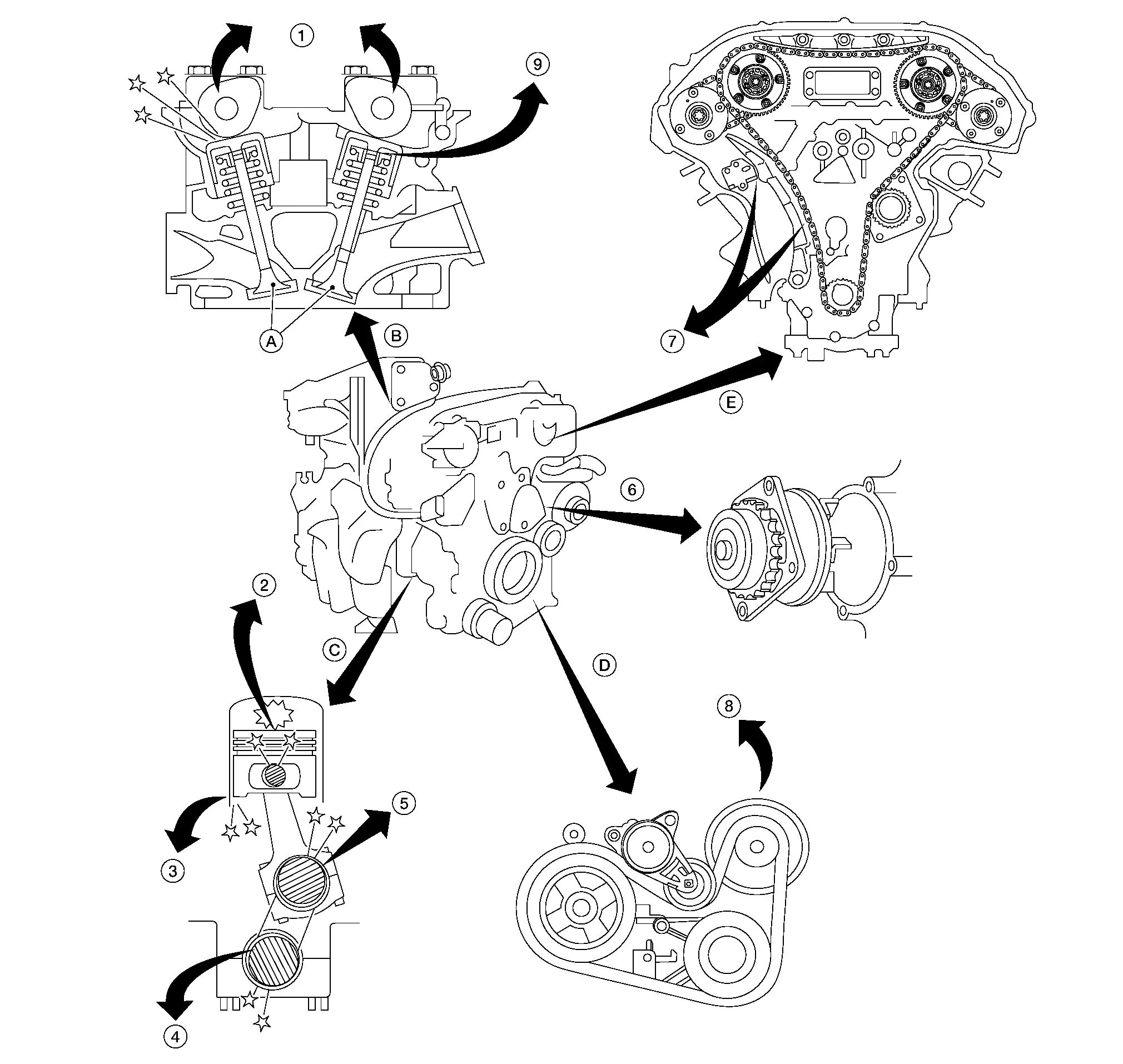
| 1. | Camshaft bearing noise | 2. | Piston pin noise | 3. | Piston slap noise |
| 4. | Main bearing noise | 5. | Connecting rod bearing noise | 6. | Water pump noise |
| 7. | Timing chain and chain tensioner noise | 8. | Drive belt noise (Sticking/Slipping) | 9. | Tappet noise |
| A. | Valve | B. | Valve mechanism | C. | Rotation mechanism |
| D. | Drive belt | E. | Timing chain |
Use the Chart Below to Help You Find the Cause of the Symptom
Locate the area where noise occurs.
Confirm the type of noise.
Specify the operating condition of engine.
Check specified noise source. Repair or replace the identified part as necessary.
| Location of noise | Type of noise | Operating condition of engine | Source of noise | Check item | Reference page | |||||
|---|---|---|---|---|---|---|---|---|---|---|
| Before warm-up | After warm-up | When starting | When idling | When racing | While driving | |||||
Top of engine Rocker cover Cylinder head |
Ticking or clicking | C | A | — | A | B | — | Tappet noise | Valve clearance | Valve Clearance |
| Rattle | C | A | — | A | B | C | Camshaft bearing noise | Camshaft journal clearance Camshaft runout |
Removal and Installation | |
Crankshaft pulley Cylinder block (Side of engine) Oil pan |
Slap or knock | — | A | — | B | B | — | Piston pin noise | Piston and piston pin clearance Connecting rod bushing clearance |
Inspection |
| Slap or rap | A | — | — | B | B | A | Piston slap noise | Piston-to-bore clearance Piston ring side clearance Piston ring end gap Connecting rod bend and torsion |
Inspection | |
| Knock | A | B | C | B | B | B | Connecting rod bearing noise | Connecting rod bushing clearance (Small end) Connecting rod bearing clearance (Big end) |
Inspection | |
| Knock | A | B | — | A | B | C | Main bearing noise | Main bearing oil clearance Crankshaft runout |
Inspection | |
Front of engine Timing chain cover |
Tapping or ticking | A | A | — | B | B | B | Timing chain and chain tensioner noise | Timing chain cracks and wear Timing chain tensioner operation |
Removal and Installation |
| Front of engine | Squeaking or fizzing | A | B | — | B | — | C | Drive belts (Sticking or slipping) | Drive belts deflection | Checking Drive Belt |
| Creaking | A | B | A | B | A | B | Drive belts (Slipping) | Idler pulley bearing operation | ||
Squall Creak |
A | B | — | B | A | B | Water pump noise | Water pump operation | Removal and Installation | |
A: Closely related B: Related C: Sometimes related —: Not related
Unit Removal and Installation. Engine Assembly ➤ Nissan Pathfinder SUV
Unit Disassembly and Assembly. Cylinder Block ➤ Nissan Pathfinder 2026
Service Data and Specifications (SDS) Nissan Pathfinder SUV
General Specification
GENERAL SPECIFICATIONS
| Cylinder arrangement | V-6 | ||||
| Displacement cm3 (cu in) | 3,498 (213.45) | ||||
| Bore and stroke mm (in) | 96 x 81 (3.78 x 3.19) | ||||
| Valve arrangement | DOHC | ||||
| Firing order | 1-2-3-4-5-6 | ||||
| Number of piston rings | Compression | 2 | |||
| Oil | 1 | ||||
| Number of main bearings | 4 | ||||
| Compression ratio | 11.0:1 | ||||
| Compression pressure kPa (kg/cm2, psi)/300 rpm | Standard | 1,275 (13.0, 185) | |||
| Minimum | 981 (10.0, 142) | ||||
| Differential limit between cylinders | 98 (1.0, 14) | ||||
| Cylinder number |  |
||||
Valve timing (Valve timing control - “OFF”)
(A): TDC (E): BDC |
 |
||||
| Unit: degree | |||||
| B | C | D | F | G | H |
| 3 | 256 | 90 | 73 | 240 | -30 |
 : Intake valve
 : Exhaust valve
Drive Belt
DRIVE BELT
| Tension of drive belt | Belt tension is not manually adjustable, as it is automatically adjusted by drive belt auto-tensioner. |
Spark Plug
SPARK PLUG
Unit: mm (in)
| Make | DENSO | |
| Standard type* | FXE22HR11 | |
| Gap | Standard | 1.1 (0.043) |
*: Always check with the Parts Department for the latest parts information.
Intake Manifold
INTAKE MANIFOLD
Unit: mm (in)
| Items | Limit | |
| Surface distortion | Intake manifold | 0.1 (0.004) |
Exhaust Manifold
EXHAUST MANIFOLD
Unit: mm (in)
| Items | Limit | |
| Surface distortion | Exhaust manifold | 0.3 (0.012) |
Camshaft
CAMSHAFT
Unit: mm (in)
| Items | Standard | Limit | |||
| Camshaft journal oil clearance | No. 1 | 0.045 - 0.086 (0.0018 - 0.0034) | 0.15 (0.0059) | ||
| No. 2, 3, 4 | 0.035 - 0.076 (0.0014 - 0.0030) | ||||
| Camshaft bracket inner diameter | No. 1 | 26.000 - 26.021 (1.0236 - 1.0244) | — | ||
| No. 2, 3, 4 | 23.500 - 23.521 (0.9252 - 0.9260) | — | |||
| Camshaft journal diameter | No. 1 | 25.935 - 25.955 (1.0211 - 1.0218) | — | ||
| No. 2, 3, 4 | 23.445 - 23.465 (0.9230 - 0.9238) | — | |||
| Camshaft end play | 0.115 - 0.188 (0.0045 - 0.0074) | 0.24 (0.0094) | |||
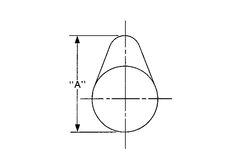
| Camshaft lobe height “A” | Intake | 45.665 - 45.855 (1.7978 - 1.8053) | 0.2 (0.008)*1 | ||
| Exhaust | 45.875 - 46.065 (1.8061 - 1.8136) | 0.2 (0.008)*1 | |||
| Camshaft runout [TIR*2] | Less than 0.02 (0.0008) | 0.05 (0.0020) | |||
| Camshaft sprocket runout [TIR*2] | Less than 0.15 (0.0059) | — | |||
 |
|||||
*1: Cam wear limit
*2: Total indicator reading
VALVE LIFTER
Unit: mm (in)
| Items | Standard |
| Valve lifter outer diameter | 33.977 - 33.987 (1.3377 - 1.3381) |
| Valve lifter bore diameter | 34.000 - 34.016 (1.3386 - 1.3392) |
| Valve lifter clearance | 0.013 - 0.039 (0.0005 - 0.0015) |
VALVE CLEARANCE
Unit: mm (in)
| Items | Cold | Hot* (reference data) |
| Intake | 0.26 - 0.34 (0.010 - 0.013) | 0.304 - 0.416 (0.012 - 0.016) |
| Exhaust | 0.29 - 0.37 (0.011 - 0.015) | 0.308 - 0.432 (0.012 - 0.017) |
*: Approximately 80 °C
AVAILABLE VALVE LIFTER
Unit: mm (in)
| Identification mark (A)* | Thickness (B) |
|---|---|
 |
|
| 300 | 3.00 (0.1181) |
| 302 | 3.02 (0.1188) |
| 304 | 3.04 (0.1196) |
| 306 | 3.06 (0.1204) |
| 308 | 3.08 (0.1212) |
| 310 | 3.10 (0.1220) |
| 312 | 3.12 (0.1228) |
| 314 | 3.14 (0.1236) |
| 316 | 3.16 (0.1244) |
| 318 | 3.18 (0.1251) |
| 320 | 3.20 (0.1259) |
| 322 | 3.22 (0.1267) |
| 324 | 3.24 (0.1275) |
| 326 | 3.26 (0.1283) |
| 328 | 3.28 (0.1291) |
| 330 | 3.30 (0.1299) |
| 332 | 3.32 (0.1307) |
| 334 | 3.34 (0.1314) |
| 336 | 3.36 (0.1322) |
| 338 | 3.38 (0.1330) |
| 340 | 3.40 (0.1338) |
| 342 | 3.42 (0.1346) |
| 344 | 3.44 (0.1354) |
| 346 | 3.46 (0.1362) |
| 348 | 3.48 (0.1370) |
| 350 | 3.50 (0.1377) |
*: Always check with the Parts Department for the latest parts information.
Cylinder Head
CYLINDER HEAD
Unit: mm (in)
| Items | Standard | Limit |
|---|---|---|
| Head surface distortion | Less than 0.03 (0.0012) | 0.1 (0.004) |
| Normal cylinder head height (H) | 126.3 - 126.5 (4.97 - 4.98) | — |
| Spark plug tube installation height | 38.2 +0.9/- 0.5 (1.5 +0.035 / -0.020) | — |
 |
||
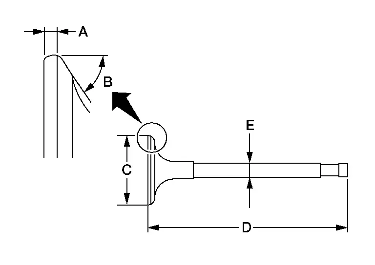
VALVE DIMENSIONS
Unit: mm (in)
 |
||
| Valve head diameter (C) | Intake | 37.1 - 37.3 (1.4606 - 1.4685) |
| Exhaust | 30.35 - 30.65 (1.1949 - 1.2067) | |
| Valve length (D) | Intake | 102.49 (4.0350) |
| Exhaust | 100.1 (3.9409) | |
| Valve stem diameter (E) | Intake | 5.965 - 5.980 (0.2348 - 0.2354) |
| Exhaust | 5.955 - 5.970 (0.2344 - 0.2350) | |
| Valve seat angle (B) | Intake | 45°15′ - 45°45′ |
| Exhaust | ||
| Valve margin (A) | Intake | 1.15 - 1.45 (0.0453 - 0.0571) |
| Exhaust | 1.41 - 1.71 (0.0555 - 0.0673) | |
| Valve margin (A) limit | More than 0.5 (0.0197) | |
| Valve stem end surface grinding limit | Less than 0.2 (0.0079) | |
VALVE OIL SEAL
Unit: mm (in)
| Items | Standard | ||
|---|---|---|---|
 |
|||
| Height (H) (without valve spring installed) | 14.300 - 14.900 (0.5630 - 0.5870) | ||
(A) : Suitable tool
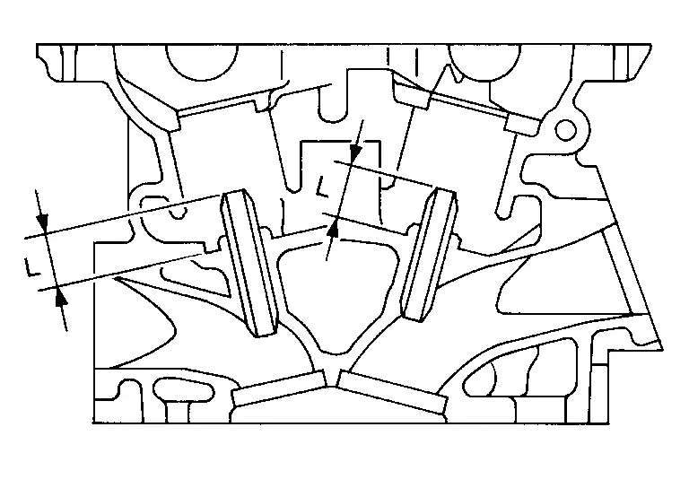
VALVE GUIDE
Unit: mm (in)
 |
|||
| Items | Standard | Oversize (Service) [0.2 (0.008)] | |
| Valve guide | Outer diameter | 10.023 - 10.034 (0.3946 - 0.3950) | 10.223 - 10.234 (0.4025 - 0.4029) |
| Inner diameter (Finished size) | 6.000 - 6.018 (0.2362 - 0.2369) | ||
| Cylinder head valve guide hole diameter | 9.975 - 9.996 (0.3927 - 0.3935) | 10.175 - 10.196 (0.4006 - 0.4014) | |
| Interference fit of valve guide | 0.027 - 0.059 (0.0011 - 0.0023) | ||
| Items | Standard | Limit | |
| Valve guide clearance | Intake | 0.020 - 0.053 (0.0008 - 0.0021) | 0.08 (0.0031) |
| Exhaust | 0.040 - 0.073 (0.0016 - 0.0029) | 0.01 (0.004) | |
Valve deflection |
Intake | — | 0.24 (0.0094) |
| Exhaust | — | 0.28 (0.0110) | |
| Projection length (L) | 12.6 - 12.8 (0.496 - 0.504) | ||
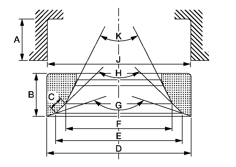
VALVE SEAT
Unit: mm (in)
| Items | Standard | Oversize (Service) [0.5 (0.02)] | |
|---|---|---|---|
 |
|||
| Cylinder head seat recess diameter (J) | Intake | 38.000 - 38.016 (1.4961 - 1.4967) | 38.500 - 38.516 (1.5157 - 1.5164) |
| Exhaust | 31.600 - 31.616 (1.2441 - 1.2447) | 32.100 - 32.116 (1.2638 - 1.2644) | |
| Valve seat outer diameter (D) | Intake | 38.097 - 38.113 (1.4999 - 1.5005) | 38.597 - 38.613 (1.5196 - 1.5202) |
| Exhaust | 31.708 - 31.724 (1.2483 - 1.2490) | 32.208 - 32.224 (1.2680 - 1.2687) | |
| Valve seat interference fit | Intake | 0.081 - 0.113 (0.0032 - 0.0044) | |
| Exhaust | 0.064 - 0.096 (0.0025 - 0.0038) | ||
| Diameter (F)*1 | Intake | 34.6 (1.362) | |
| Exhaust | 27.98 (1.102) | ||
| Diameter (E)*2 | Intake | 35.9 - 36.4 (1.413 - 1.433) | |
| Exhaust | 29.55 - 30.05 (1.1634 - 1.1831) | ||
| Angle (K) | Intake | 30° | |
| Exhaust | 30° | ||
| Angle (H) | Intake | 45° | |
| Exhaust | 45° | ||
| Angle (G) | Intake | 60° | |
| Exhaust | 60° | ||
| Contacting width (C)*3 | Intake | 1.0 - 1.4 (0.0394 - 0.0551) | |
| Exhaust | 1.2 - 1.6 (0.0472 - 0.0630) | ||
| Valve seat height (B) | Intake | 6.2 - 6.3 (0.2441 - 0.2480) | 5.0 - 5.1 (0.197 - 0.201) |
| Exhaust | 5.9 - 6.0 (0.232 - 0.236) | 4.9 - 5.0 (0.193 - 0.197) | |
| Cylinder head seat recess depth (A) | 6.3 (0.2480) | ||
*1: Diameter made by intersection point of conic angles “K” and “H”
*2: Diameter made by intersection point of conic angles “H” and “G”
*3: Machining data
VALVE SPRING
| Items | Standard |
|---|---|
| Free height | 48.51 mm (1.9098 in) |
| Installation height | 38.66 mm (1.5220 in) |
| Installation load | 166 - 188 N (16.9 - 19.2 kg, 37 - 42 lb) |
| Height during valve open | 28.66 mm (1.1283 in) |
| Load with valve open | 384 - 432 N (39.2 - 44.1 kg, 86.3 - 97.1 lb) |
Unit: mm (in)
| Items | Limit |
|---|---|
| Squareness | 1.7 (0.067) |
Cylinder Block
CYLINDER BLOCK
Unit: mm (in)
 |
||||
| Surface distortion | Standard | Less than 0.03 (0.0012) | ||
| Limit | 0.10 (0.0039) | |||
| Main bearing housing inner diameter | Standard | 63.993 - 64.017 (2.5194 - 2.5203) | ||
| Cylinder bore | Inner diameter | Standard* | Grade No. 1 | 95.500 - 95.510 (3.7598 - 3.7602) |
| Grade No. 2 | 95.510 - 95.520 (3.7602 - 3.7606) | |||
| Grade No. 3 | 95.520 - 95.530 (3.7606 - 3.7610) | |||
| Wear limit | 0.20 (0.0079) | |||
| Out-of-round [Difference between (B) and (A)] | Limit | 0.015 (0.0006) | ||
| Taper [Difference between (C) and (E)] | 0.010 (0.0004) | |||
| Main bearing housing inner diameter grade (Without bearing)* | Grade No. A Grade No. B Grade No. C Grade No. D Grade No. E Grade No. F Grade No. G Grade No. H Grade No. J Grade No. K Grade No. L Grade No. M Grade No. N Grade No. P Grade No. R Grade No. S Grade No. T Grade No. U Grade No. V Grade No. W Grade No. X Grade No. Y Grade No. 4 Grade No. 7 |
63.993 - 63.994 (2.5194 - 2.5194) 63.994 - 63.995 (2.5194 - 2.5195) 63.995 - 63.996 (2.5195 - 2.5195) 63.996 - 63.997 (2.5195 - 2.5196) 63.997 - 63.998 (2.5196 - 2.5196) 63.998 - 63.999 (2.5196 - 2.5196) 63.999 - 64.000 (2.5196 - 2.5197) 64.000 - 64.001 (2.5197 - 2.5197) 64.001 - 64.002 (2.5197 - 2.5198) 64.002 - 64.003 (2.5198 - 2.5198) 64.003 - 64.004 (2.5198 - 2.5198) 64.004 - 64.005 (2.5198 - 2.5199) 64.005 - 64.006 (2.5199 - 2.5199) 64.006 - 64.007 (2.5199 - 2.5200) 64.007 - 64.008 (2.5200 - 2.5200) 64.008 - 64.009 (2.5200 - 2.5200) 64.009 - 64.010 (2.5200 - 2.5201) 64.010 - 64.011 (2.5201 - 2.5201) 64.011 - 64.012 (2.5201 - 2.5202) 64.012 - 64.013 (2.5202 - 2.5202) 64.013 - 64.014 (2.5202 - 2.5202) 64.014 - 64.015 (2.5202 - 2.5203) 64.015 - 64.016 (2.5203 - 2.5203) 64.016 - 64.017 (2.5203 - 2.5203) |
||
| Difference in inner diameter between cylinders | Standard | Less than 0.03 (0.0012) | ||
(F) : 120 mm (4.72 in)
(G) : 60 mm (2.36 in)
(H) : 10 mm (0.39 in)
(*) : Always check with the Parts Department for the latest parts information.
AVAILABLE PISTON
Unit: mm (in)
 |
|||
| Items | Grade* | Standard | |
| Piston skirt diameter (A) | Grade No. 1 | 95.470 - 95.480 (3.7587 - 3.7590) | |
| Grade No. 2 | 95.480 - 95.490 (3.7590 - 3.7594) | ||
| Grade No. 3 | 95.490 - 95.500 (3.7594 - 3.7598) | ||
| (a) dimension | 38.0 (1.496) | ||
| Piston pin hole diameter | 21.995 - 21.999 (0.8659 - 0.8661) | ||
| Piston to cylinder bore clearance | 0.020 - 0.040 (0.0008 - 0.0016) | ||
*: Always check with the Parts Department for the latest parts information.
PISTON RING
Unit: mm (in)
| Items | Standard | Limit | |
| Side clearance | Top | 0.045 - 0.080 (0.0018 - 0.0031) | 0.11 (0.0043) |
| 2nd | 0.030 - 0.070 (0.0012 - 0.0028) | 0.1 (0.004) | |
| Oil ring | 0.045 - 0.125 (0.0018 - 0.0049) | — | |
| End gap | Top | 0.24 - 0.29 (0.0094 - 0.0114) | 0.51 (0.0201) |
| 2nd | 0.33 - 0.43 (0.0130 - 0.0169) | 0.62 (0.0244) | |
| Oil (rail ring) | 0.20 - 0.45 (0.0079 - 0.0177) | 0.80 (0.0315) | |
PISTON PIN
Unit: mm (in)
| Items | Standard | Limit | |
| Piston pin outer diameter | 21.989 - 21.993 (0.8657 - 0.8659) | — | |
| Piston to piston pin oil clearance | 0.002 - 0.010 (0.0001 - 0.0004) | — | |
| Connecting rod bushing oil clearance | 0.005 - 0.017 (0.0002 - 0.0007) | 0.030 (0.0012) | |
CONNECTING ROD
Unit: mm (in)
| Items | Standard | Limit | |
| Center distance | 144.15 - 144.25 (5.68 - 5.68) | — | |
| Bend [per 100 (3.94)] | — | 0.15 (0.0059) | |
| Torsion [per 100 (3.94)] | — | 0.30 (0.0118) | |
| Connecting rod small end inner diameter | 23.980 - 24.000 (0.9441 - (0.9449) | ||
| Connecting rod bushing inner diameter1 | 22.000 - 22.012 (0.8661 - 0.8666) | — | |
| Connecting rod big end diameter (Without bearing) | 55.000 - 55.013 (2.1654 - 2.1659) | — | |
| Side clearance | 0.20 - 0.35 (0.0079 - 0.0138) | 0.40 (0.0157) | |
1: After installing in connecting rod.
CRANKSHAFT
Unit: mm (in)
 |
 |
||
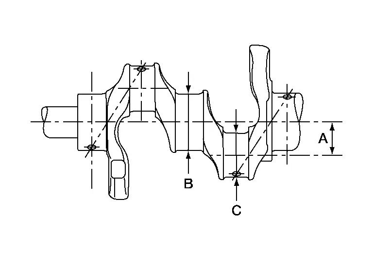
| Main journal diameter.(B) grade | Standard | Grade1 | Dimension |
Grade No. A Grade No. B Grade No. C Grade No. D Grade No. E Grade No. F Grade No. G Grade No. H Grade No. J Grade No. K Grade No. L Grade No. M Grade No. N Grade No. P Grade No. R Grade No. S Grade No. T Grade No. U Grade No. V Grade No. W Grade No. X Grade No. Y Grade No. 4 Grade No. 7 |
59.975 - 59.974 (2.3612 - 2.3612) 59.974 - 59.973 (2.3612 - 2.3611) 59.973 - 59.972 (2.3611 - 2.3611) 59.972 - 59.971 (2.3611 - 2.3611) 59.971 - 59.970 (2.3611 - 2.3610) 59.970 - 59.969 (2.3610 - 2.3610) 59.969 - 59.968 (2.3610 - 2.3609) 59.968 - 59.967 (2.3609 - 2.3609) 59.967 - 59.966 (2.3609 - 2.3609) 59.966 - 59.965 (2.3609 - 2.3608) 59.965 - 59.964 (2.3608 - 2.3608) 59.964 - 59.963 (2.3608 - 2.3607) 59.963 - 59.962 (2.3607 - 2.3607) 59.962 - 59.961 (2.3607 - 2.3607) 59.961 - 59.960 (2.3607 - 2.3606) 59.960 - 59.959 (2.3606 - 2.3606) 59.959 - 59.958 (2.3606 - 2.3605) 59.958 - 59.957 (2.3605 - 2.3605) 59.957 - 59.956 (2.3605 - 2.3605) 59.956 - 59.955 (2.3605 - 2.3604) 59.955 - 59.954 (2.3604 - 2.3604) 59.954 - 59.953 (2.3604 - 2.3603) 59.953 - 59.952 (2.3603 - 2.3603) 59.952 - 59.951 (2.3603 - 2.3603) |
||
| Pin journal diameter. (C) grade | Standard | Grade No. 0 | 51.968 - 51.974 (2.0460 - 2.0462) |
| Grade No. 1 | 51.962 - 51.968 (2.0457 - 2.0460) | ||
| Grade No. 2 | 51.956 - 51.962 (2.0445 - 2.0457) | ||
| Center distance (A) | 40.66 - 40.74 (1.6008 - 1.6039) | ||
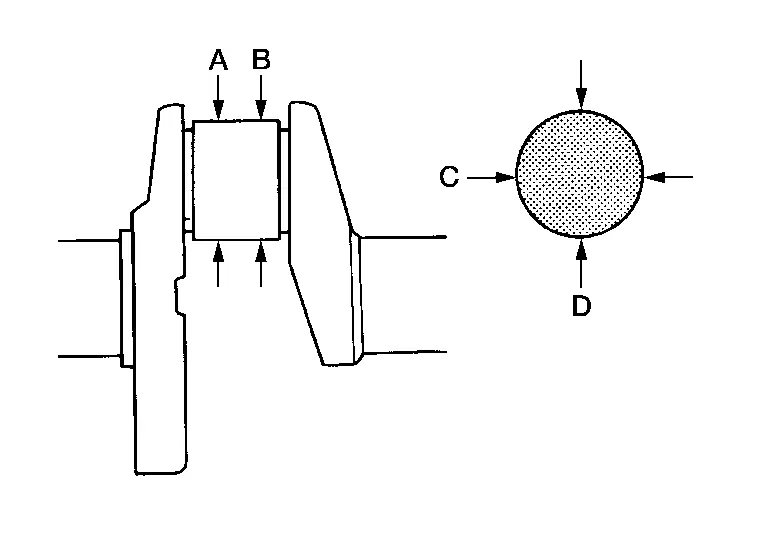
| Taper [Difference between (A) and (B)] | Limit | Less than 0.002 (0.0001) | |
| Out-of-round [Difference between (C) and (D)] | Less than 0.0025 (0.0001) | ||
| Crankshaft runout [TIR*] | Standard | Less than 0.05 (0.0020) | |
| Limit | 0.10 (0.0039) | ||
| Crankshaft end play | Standard | 0.10 - 0.25 (0.0039 - 0.0098) | |
| Limit | 0.30 (0.0118) | ||
| Fillet role of crankshaft journal | Standard | More than 0.10 (0.0039) | |
*: Total indicator reading
(1) : Always check with the Parts Department for the latest parts information.
Main Bearing
MAIN BEARING
Unit: mm (in)
| Grade number* | Thickness | Width | Identification color | Remarks | |
| 0 | 2.000 - 2.003 (0.0787 - 0.0789) | 19.9 - 20.1 (0.783 - 0.791) |
Black | Grade is the same for upper and lower bearings. | |
| 1 | 2.003 - 2.006 (0.0789 - 0.0790) | Brown | |||
| 2 | 2.006 - 2.009 (0.0790 - 0.0791) | Green | |||
| 3 | 2.009 - 2.012 (0.0791 - 0.0792) | Yellow | |||
| 4 | 2.012 - 2.015 (0.0792 - 0.0793) | Blue | |||
| 5 | 2.015 - 2.018 (0.0793 - 0.0794) | Pink | |||
| 6 | 2.018 - 2.021 (0.0794 - 0.0796) | Purple | |||
| 7 | 2.021 - 2.024 (0.0796 - 0.0797) | White | |||
| 01 | UPR | 2.003 - 2.006 (0.0789 - 0.0790) | Brown | Grade and color are different for upper and lower bearings. | |
| LWR | 2.000 - 2.003 (0.0787 - 0.0789) | Black | |||
| 12 | UPR | 2.006 - 2.009 (0.0790 - 0.0791) | Green | ||
| LWR | 2.003 - 2.006 (0.0789 - 0.0790) | Brown | |||
| 23 | UPR | 2.009 - 2.012 (0.0791 - 0.0792) | Yellow | ||
| LWR | 2.006 - 2.009 (0.0790 - 0.0791) | Green | |||
| 34 | UPR | 2.012 - 2.015 (0.0792 - 0.0793) | Blue | ||
| LWR | 2.009 - 2.012 (0.0791 - 0.0792) | Yellow | |||
| 45 | UPR | 2.015 - 2.018 (0.0793 - 0.0794) | Pink | ||
| LWR | 2.012 - 2.015 (0.0792 - 0.0793) | Blue | |||
| 56 | UPR | 2.018 - 2.021 (0.0794 - 0.0796) | Purple | ||
| LWR | 2.015 - 2.018 (0.0793 - 0.0794) | Pink | |||
| 67 | UPR | 2.021 - 2.024 (0.0796 - 0.0797) | White | ||
| LWR | 2.018 - 2.021 (0.0794 - 0.0796) | Purple | |||
*: Always check with the Parts Department for the latest parts information.
UNDERSIZE
Unit: mm (in)
| Items | Thickness | Main journal diameter |
| 0.25 (0.0098) | 2.133 - 2.141 (0.0840 - 0.0843) | Grind so that bearing clearance is the specified value. |
MAIN BEARING OIL CLEARANCE
Unit: mm (in)
| Items | Standard | Limit |
| Main bearing oil clearance | 0.029 - 0.042 (0.0011 - 0.0017)* | 0.065 (0.0026) |
*: Actual clearance
Connecting Rod Bearing
CONNECTING ROD BEARING
Unit: mm (in)
| Grade number* | Thickness | Identification color (mark) |
| 0 | 1.500 - 1.503 (0.0591 - 0.0592) | Black |
| 1 | 1.503 - 1.506 (0.0592 - 0.0593) | Brown |
| 2 | 1.506 - 1.509 (0.0593 - 0.0594) | Green |
*: Always check with the Parts Department for the latest parts information.
UNDERSIZE
Unit: mm (in)
| Items | Thickness | Crank pin journal diameter (Dp) |
| 0.25 (0.0098) | 1.626 - 1.634 (0.0640 - 0.0643) | Grind so that bearing clearance is the specified value. |
CONNECTING ROD BEARING OIL CLEARANCE
Unit: mm (in)
| Items | Standard | Limit |
| Connecting rod bearing oil clearance | 0.029 - 0.056 (0.0011 - 0.0022)* | 0.070 (0.0028) |
*: Actual clearance
Drive Plate
Unit: mm (in)
| Drive plate runout [TIR]* - on torque converter mount surface | Less than 0.35 (0.0138) |
| Drive plate runout [TIR]* - on ring gear | Less than 0.5 (0.0197) |
*: Total indicator reading