Engine :: Engine Mechanical

Vq35dd - Unit Disassembly and Assembly. Cylinder Block ++

In this manual: Engine :: Engine Mechanical
General Information — 8Engine :: Engine Mechanical — 19Engine Lubrication System - Precautions. Preparation — 1Engine Lubrication System - Lubrication System (System Description). Engine Oil Pressure (Basic Inspection). Service Data and Specifications (SDS) — 1Engine Cooling System - Precautions. Preparation. Service Data and Specifications (SDS) — 1Engine Cooling System - Engine Coolant — 1Engine Control System - System Description — 1System Description - Component Parts ++ — 1System Description - System ++ — 1Engine Control System - Ecu Diagnosis Information — 1Ecu Diagnosis Information - Ecm ++ — 1Engine Control System - Basic Inspection — 1Basic Inspection - Diagnosis and Repair Workflow ++ — 1Basic Inspection - Basic Inspection ++ — 1Basic Inspection - Additional Service When Replacing Ecm ++ — 1Basic Inspection - Fuel Pressure Check ++ — 1Basic Inspection - How to Set Srt Code ++ — 1Basic Inspection - How to Erase Permanent Dtc ++ — 1Engine Control System - Dtc/circuit Diagnosis — 1Engine Control System - Symptom Diagnosis — 1Engine Control System - Periodic Maintenance — 1Engine Control System - Removal and Installation — 1Fuel System - Precautions. Preparation. Service Data and Specifications (SDS) — 1Fuel System - Fuel System (Periodic Maintenance). Fuel Level Sensor Unit (Disassembly and Assembly) — 1Exhaust System - Precautions. Preparation — 1Exhaust System - Exhaust System (Periodic Maintenance). Exhaust System (Removal and Installation) — 1Starting System - Precautions. Preparation. Starter Motor (Service Data and Specifications (sds)) — 1Starting System - Diagnosis and Repair Work Flow — 1Starting System - Starting System (Symptom Diagnosis). Starter Motor (Removal and Installation) — 1Accelerator Control System - Precautions. Service Data and Specifications (SDS) — 1Accelerator Control System - Accelerator Pedal Assembly — 1Transmission & Driveline :: Transaxle & Transmission — 21Driveline - System Description — 1Transfer: Ty92b - Ecu Diagnosis Information. Awd Control Unit ++ — 1Driveline - Basic Inspection — 1Driveline - Dtc/circuit Diagnosis — 1Driveline - Symptom Diagnosis — 1Driveline - Removal and Installation — 1Transfer: Ty92b - Unit Removal and Installation. Transfer Assembly ++ — 1Driveline - Unit Disassembly and Assembly — 1Driveline - Basic Inspection — 1Driveline - Removal and Installation — 1Driveline - Unit Disassembly and Assembly — 1Front Axle - Precautions. Preparation — 1Front Axle - Noise, Vibration and Harshness (nvh) Troubleshooting (Symptom Diagnosis). Service Data and Specifications (SDS) — 1Front Axle - Front Drive Shaft Boot — 1Front Axle - Front Drive Shaft — 1Rear Axle - Precautions. Preparation. Service Data and Specifications (SDS) — 1Rear Axle - Noise, Vibration and Harshness (nvh) Troubleshooting — 1Rear Axle - Rear Drive Shaft — 1Suspension :: Front Suspension — 7Rear Suspension - Precautions. Preparation — 1Rear Suspension - Noise, Vibration and Harshness (nvh) Troubleshooting (Symptom Diagnosis). Service Data and Specifications (SDS) — 1Rear Suspension - Rear Suspension Assembly — 1Road Wheels & Tires - Precautions — 1Road Wheels & Tires - Preparation. Bcm (Ecu Diagnosis Information). Service Data and Specifications (SDS) — 1Road Wheels & Tires - System — 1Brakes :: Brake System — 9Parking Brake System - Precautions. Preparation — 1Parking Brake System - System — 1Vdc/tcs/abs - Precautions ++ — 1Brake Control System - System Description — 1System Description - Component Parts ++ — 1System Description - System ++ — 1Brake Control System - Basic Inspection — 1Brake Control System - Symptom Diagnosis — 1Brake Control System - Removal and Installation — 1Brake Control System - System Description — 1Brake Control System - Dtc/circuit Diagnosis — 1Brake Control System - Removal and Installation — 1Brake Control System - System Description — 1Brake Control System - Basic Inspection — 1Brake Control System - Symptom Diagnosis — 1Brake Control System - System Description — 1Brake Control System - Basic Inspection — 1Brake Control System - Symptom Diagnosis — 1Steering :: Steering System — 9Steering Control System - Precautions — 1Steering Control System - System — 1Steering Control System - Eps Control Unit (Ecu Diagnosis Information. Removal and Installation) — 1Restraints :: Seat Belt — 7Srs Air Bag - Precautions. Preparation — 1Srs Air Bag - Collision Diagnosis — 1Srs Air Bag - Occupant Classification System — 1Srs Air Bag Control System - Precautions — 1Srs Air Bag Control System - System — 1Srs Air Bag Control System - Diagnosis Sensor Unit — 1Srs Air Bag Control System - Inspection and Adjustment — 1Ventilation, Heater & Air Conditioner :: Ventilation System — 6Heater & Air Conditioning System - Precautions — 1Heater & Air Conditioning System - Preparation — 1Heater & Air Conditioning System - Component Parts — 1Heater & Air Conditioning System - Diagnosis and Repair Work Flow — 1Heater & Air Conditioning System - Compressor — 1Heater & Air Conditioning System - Cooler Pipe and Hose — 1Heater & Air Conditioning System - Condenser. Condenser — 1Heater & Air Conditioning System - Heating and Cooling Unit Assembly — 1Heater & Air Conditioning System - Service Data and Specifications (SDS) — 1Heater & Air Conditioning Control System - System Description — 1System Description - Component Parts ++ — 1System Description - System ++ — 1System Description - Operation ++ — 1Heater & Air Conditioning Control System - Ecu Diagnosis Information — 1Heater & Air Conditioning Control System - Basic Inspection — 1Heater & Air Conditioning Control System - Dtc/circuit Diagnosis — 1Heater & Air Conditioning Control System - Symptom Diagnosis — 1Heater & Air Conditioning Control System - Removal and Installation — 1Body Interior :: Interior — 8Instrument Panel - Precautions. Preparation. Clip List — 1Instrument Panel - Squeak and Rattle Trouble Diagnoses — 1Instrument Panel - Cluster Lid C — 1Seat - Precautions — 1Seat - Preparation. Clip List — 1Seat - Component Parts — 1Seat - System — 1Seat - Diagnosis and Repair Work Flow — 1Seat - Front Seat — 1Seat - Second Row Seats — 1Seat - Third Row Seats — 1Seat - Front Seat — 1Seat - Second Row Seat — 1Seat - Third Row Seat — 1Automatic Drive Positioner - Precautions. Preparation — 1Automatic Drive Positioner - System — 1Automatic Drive Positioner - Diagnosis and Repair Work Flow — 1Automatic Drive Positioner - Inspection and Adjustment — 1Body Exterior, Doors, Roof & Vehicle Security :: Door & Lock — 38Security Control System - Precautions — 1Security Control System - System — 1Security Control System - Ecm, Bcm, Intelligent Key Unit, Ipdm E/r — 1Security Control System - Vehicle Security System Cannot Be Set — 1Glass & Window System - Precautions. Preparation — 1Glass & Window System - Squeak and Rattle Trouble Diagnoses — 1Power Window Control System - Precautions. Preparation — 1Power Window Control System - Power Supply and Ground Circuit — 1Power Window Control System - Power Window Motor Circuit — 1Power Window Control System - Front Power Window Rh Alone Does Not Operate — 1Power Window Control System - Rear Lh Side Power Window Alone Does Not Operate — 1Power Window Control System - Rear Rh Side Power Window Alone Does Not Operate — 1Roof - Precautions. Preparation — 1Roof - Power Supply and Ground Circuit — 1Roof - Moonroof Switch Assembly — 1Roof - Lin Communication Circuit — 1Roof - Auto Operation Does Not Operate — 1Roof - Anti-Pinch Function Does Not Operate — 1Exterior - Precautions. Preparation. Clip List (Preparation) — 1Exterior - Squeak and Rattle Trouble Diagnoses — 1Exterior - Fender Protector — 1Exterior - Over Fender — 1Exterior - Under Cover — 1Exterior - Roof Side Rail — 1Body Repair - Service Information — 1Service Information - Sheet Metal Work ++ — 1Service Information - Body Welding and Precautions ++ — 1Service Information - Safety and Health ++ — 1Service Information - Repairing Procedures and Precautions ++ — 1Body Repair - Precaution — 1Body Repair - Preparation — 1Body Repair - Removal and Installation — 1Driver Controls :: Mirrors — 8Exterior Lighting System - System Description — 1System Description - Component Parts ++ — 1Exterior Lighting System - Basic Inspection — 1Exterior Lighting System - Dtc/circuit Diagnosis — 1Exterior Lighting System - Symptom Diagnosis — 1Exterior Lighting System - Periodic Maintenance — 1Exterior Lighting System - Removal and Installation — 1Interior Lighting System - Precautions. Preparation — 1Interior Lighting System - Component Parts. Interior Lighting System — 1Interior Lighting System - System — 1Interior Lighting System - Diagnosis and Repair Work Flow — 1Interior Lighting System - Interior Lighting System Symptoms (Symptom Diagnosis). Bcm (Ecu Diagnosis Information). Service Data and Specifications (SDS) — 1Interior Lighting System - Foot Lamp — 1Wiper & Washer - Precautions — 1Wiper & Washer - Preparation. Bcm, Ipdm E/r (Ecu Diagnosis Information). Service Data and Specifications (SDS) — 1Wiper & Washer - System — 1Wiper & Washer - Diagnosis and Repair Work Flow — 1Defogger - Precautions. Bcm, A/c Auto Amp. (Ecu Diagnosis Information) — 1Defogger - Diagnosis and Repair Work Flow — 1Horn - Precautions — 1Electrical & Power Control :: Power Outlet — 13Body Control System - Precautions. Preparation — 1Body Control System - Component Parts — 1Body Control System - System — 1Body Control System - Diagnosis System (bcm) — 1Body Control System - Bcm — 1Lan System - System Description — 1Lan System - System Description — 1Lan System - Dtc/circuit Diagnosis — 1Lan System - System Description — 1Lan System - Dtc/circuit Diagnosis — 1Power Control System - System Description — 1Power Control System - Basic Inspection — 1Power Control System - Dtc/circuit Diagnosis — 1Power Control System - System Description — 1Power Control System - Basic Inspection — 1Power Control System - Dtc/circuit Diagnosis — 1Power Control System - Removal and Installation — 1Charging System - Precautions. Preparation. Ecm, Ipdm E/r (Ecu Diagnosis Information) — 1Charging System - Diagnosis and Repair Work Flow — 1Charging System - Charging System (Symptom Diagnosis). Generator (Removal and Installation). Service Data and Specifications (SDS) — 1Power Supply, Ground & Circuit Elements - Precautions. Preparation. Service Data and Specifications (SDS) — 1Driver Information & Multimedia :: Meter, Warning Lamp & Indicator — 25Warning Chime System - Application Notice (How to Use This Manual). Precautions — 1Warning Chime System - System — 1Warning Chime System - Diagnosis System (combination Meter) — 1Warning Chime System - Bcm, Combination Meter (Ecu Diagnosis Information). Diagnosis and Repair Work Flow (Basic Inspection) — 1Sonar System - Precautions. Preparation — 1Sonar System - Sonar Control Unit — 1Dtc/circuit Diagnosis - B2720 Corner Sensor [rl] ++ — 1Audio, Visual & Navigation System - System Description — 1System Description - Component Parts ++ — 1System Description - System ++ — 1Audio, Visual & Navigation System - Ecu Diagnosis Information — 1Audio, Visual & Navigation System - Basic Inspection — 1Audio, Visual & Navigation System - Dtc/circuit Diagnosis — 1Dtc/circuit Diagnosis - Multi Av (av Control Unit) ++ — 1Audio, Visual & Navigation System - Symptom Diagnosis — 1Symptom Diagnosis - Multi Av System ++ — 1Audio, Visual & Navigation System - Removal and Installation — 1Audio, Visual & Navigation System - System Description — 1Audio, Visual & Navigation System - Ecu Diagnosis Information — 1Audio, Visual & Navigation System - Basic Inspection — 1Audio, Visual & Navigation System - Dtc/circuit Diagnosis — 1Audio, Visual & Navigation System - Symptom Diagnosis — 1Audio, Visual & Navigation System - Removal and Installation — 1Audio, Visual & Navigation System - System Description — 1Audio, Visual & Navigation System - Basic Inspection — 1Audio, Visual & Navigation System - Dtc/circuit Diagnosis — 1Audio, Visual & Navigation System - Symptom Diagnosis — 1Audio, Visual & Navigation System - Removal and Installation — 1Audio, Visual & Navigation System - System Description — 1Audio, Visual & Navigation System - Basic Inspection — 1Audio, Visual & Navigation System - Dtc/circuit Diagnosis — 1Audio, Visual & Navigation System - Symptom Diagnosis — 1Audio, Visual & Navigation System - Removal and Installation — 1Cruise Control & Driver Assistance :: Cruise Control System — 17Driver Assistance System - System Description — 1Driver Assistance System - Basic Inspection — 1Driver Assistance System - Dtc/circuit Diagnosis — 1Driver Assistance System - System Description — 1System Description - Component Parts ++ — 1System Description - System ++ — 1System Description - Operation ++ — 1System Description - Handling Precaution ++ — 1Driver Assistance System - Ecu Diagnosis Information — 1Driver Assistance System - Basic Inspection — 1Basic Inspection - Distance Sensor Alignment ++ — 1Basic Inspection - Camera Aiming Adjustment ++ — 1Basic Inspection - Action Test ++ — 1Driver Assistance System - Dtc/circuit Diagnosis — 1Dtc/circuit Diagnosis - Laser/radar (distance Sensor) ++ — 1Dtc/circuit Diagnosis - Lane Camera (front Camera Unit) ++ — 1Driver Assistance System - Symptom Diagnosis — 1Driver Assistance System - Removal and Installation — 1Driver Assistance System - System Description — 1System Description - System ++ — 1Driver Assistance System - Basic Inspection — 1Driver Assistance System - Dtc/circuit Diagnosis — 1Drive Mode System - Precautions — 1Drive Mode System - Component Parts. Drive Mode System — 1Drive Mode System - System — 1Drive Mode System - Diagnosis and Repair Work Flow — 1Drive Mode System - Drive Mode Select Switch Circuit — 1Maintenance - Precautions. Preparation — 1Maintenance - General Maintenance — 1Maintenance - Periodic Maintenance — 1Maintenance - Recommended Fluids and Lubricants — 1Maintenance - Engine Maintenance — 1Maintenance - Chassis and Body Maintenance — 1Engine Lubrication System - Periodic Maintenance — 1Engine Lubrication System - Removal and Installation — 1Engine Cooling System - System Description — 1Engine Cooling System - Removal and Installation — 1Engine Control System - Vq35dd — 1Fuel System - Removal and Installation — 1Starting System - System Description — 1Starting System - Dtc/circuit Diagnosis — 1Driveline - Transfer: Ty92b — 1Driveline - Rear Propeller Shaft: 3fcj-Cvj — 1Driveline - Rear Final Drive: R145 — 1Front Axle - Periodic Maintenance — 1Front Axle - Removal and Installation — 1Rear Axle - Periodic Maintenance — 1Rear Axle - Removal and Installation — 1Rear Suspension - Removal and Installation — 1Road Wheels & Tires - System Description — 1Road Wheels & Tires - Basic Inspection — 1Road Wheels & Tires - Dtc/circuit Diagnosis — 1Road Wheels & Tires - Symptom Diagnosis — 1Road Wheels & Tires - Periodic Maintenance — 1Road Wheels & Tires - Removal and Installation — 1Parking Brake System - System Description — 1Parking Brake System - Basic Inspection — 1Parking Brake System - Dtc/circuit Diagnosis — 1Parking Brake System - Symptom Diagnosis — 1Parking Brake System - Removal and Installation — 1Brake Control System - Vdc/tcs/abs — 1Brake Control System - Automatic Brake Hold — 1Brake Control System - Automatic Emergency Braking — 1Brake Control System - Rear Automatic Braking — 1Steering Control System - System Description — 1Steering Control System - Basic Inspection — 1Steering Control System - Dtc/circuit Diagnosis — 1Steering Control System - Symptom Diagnosis — 1Srs Air Bag - Removal and Installation — 1Srs Air Bag Control System - System Description — 1Srs Air Bag Control System - Basic Inspection — 1Srs Air Bag Control System - Symptom Diagnosis — 1Heater & Air Conditioning System - Symptom Diagnosis — 1Heater & Air Conditioning System - Periodic Maintenance — 1Heater & Air Conditioning Control System - Automatic Air Conditioning — 1Instrument Panel - Removal and Installation — 1Instrument Panel - Unit Disassembly and Assembly — 1Seat - Ecu Diagnosis Information — 1Seat - Dtc/circuit Diagnosis — 1Seat - Symptom Diagnosis — 1Automatic Drive Positioner - System Description — 1Automatic Drive Positioner - Ecu Diagnosis Information — 1Automatic Drive Positioner - Dtc/circuit Diagnosis — 1Automatic Drive Positioner - Symptom Diagnosis — 1Automatic Drive Positioner - Removal and Installation — 1Security Control System - System Description — 1Security Control System - Basic Inspection — 1Security Control System - Dtc/circuit Diagnosis — 1Security Control System - Symptom Diagnosis — 1Security Control System - Removal and Installation — 1Glass & Window System - Removal and Installation — 1Power Window Control System - System Description — 1Power Window Control System - Ecu Diagnosis Information — 1Power Window Control System - Basic Inspection — 1Power Window Control System - Dtc/circuit Diagnosis — 1Power Window Control System - Symptom Diagnosis — 1Power Window Control System - Removal and Installation — 1Roof - System Description — 1Roof - Ecu Diagnosis Information — 1Roof - Basic Inspection — 1Roof - Dtc/circuit Diagnosis — 1Roof - Symptom Diagnosis — 1Roof - Removal and Installation — 1Exterior - System Description — 1Exterior - Removal and Installation — 1Body Repair - Repair Information — 1Exterior Lighting System - Led Headlamp — 1Interior Lighting System - Dtc/circuit Diagnosis — 1Interior Lighting System - Removal and Installation — 1Wiper & Washer - System Description — 1Wiper & Washer - Dtc/circuit Diagnosis — 1Wiper & Washer - Symptom Diagnosis — 1Wiper & Washer - Removal and Installation — 1Defogger - System Description — 1Defogger - Dtc/circuit Diagnosis — 1Defogger - Symptom Diagnosis — 1Defogger - Removal and Installation — 1Horn - Removal and Installation — 1Body Control System - Basic Inspection — 1Body Control System - Dtc/circuit Diagnosis — 1Body Control System - Symptom Diagnosis — 1Body Control System - Removal and Installation — 1Lan System - Can Fundamental — 1Lan System - Can — 1Lan System - Can Gateway — 1Power Control System - Ipdm E/r — 1Power Control System - Power Distribution System — 1Charging System - System Description — 1Charging System - Dtc/circuit Diagnosis — 1Power Supply, Ground & Circuit Elements - System Description — 1Power Supply, Ground & Circuit Elements - Basic Inspection — 1Power Supply, Ground & Circuit Elements - Removal and Installation — 1Warning Chime System - System Description — 1Warning Chime System - Dtc/circuit Diagnosis — 1Warning Chime System - Symptom Diagnosis — 1Sonar System - System Description — 1Sonar System - Basic Inspection — 1Sonar System - Dtc/circuit Diagnosis — 1Sonar System - Symptom Diagnosis — 1Sonar System - Removal and Installation — 1Audio, Visual & Navigation System - Nissanconnect — 1Audio, Visual & Navigation System - Intelligent Around View Monitor System — 1Audio, Visual & Navigation System - Rear View Monitor System — 1Audio, Visual & Navigation System - Telematics System — 1Driver Assistance System - Adas Control Unit 2 — 1Driver Assistance System - Driver Assistance System — 1Driver Assistance System - Chassis Control — 1Drive Mode System - Removal and Installation — 1Dtc/circuit Diagnosis (C053c Wheel Speed Sensor ... U2141 Can Comm Circuit) — 1Dtc/circuit Diagnosis (P0011 Intake Valve Timing Control ... P0111 Iat Sensor) — 1Dtc/circuit Diagnosis (P0116 Engine Coolant Temperature Sensor ... P025b Fuel Pump Module a) — 1Dtc/circuit Diagnosis (P026b Injection Timing ... P0420 Three Way Catalyst Function) — 1Dtc/circuit Diagnosis (P0441 Evap Control System ... P0524 Engine Oil Pressure) — 1Dtc/circuit Diagnosis (P0532 A/c Refrigerant Pressure Sensor ... P064d Ecm) — 1Dtc/circuit Diagnosis (P06da Engine Oil Pressure Control Solenoid Valve ... P1217 Engine Over Temperature) — 1Dtc/circuit Diagnosis (P1220 Fuel Pump Control Module (fpcm) ... P1574 Ascd Vehicle Speed Sensor) — 1Dtc/circuit Diagnosis (P1575 Brake Switch ... P2101 Electric Throttle Control Function) — 1Dtc/circuit Diagnosis (P2118 Throttle Control Motor ... P34ac Electric Intake Valve Timing Control Actuator) — 1Dtc/circuit Diagnosis (Active Grille Shutter ... High Pressure Fuel Pump) — 1Dtc/circuit Diagnosis (Ignition Signal ... Variable Induction Air System) — 14012 C1040 Emergency Brake — 14013 C106a Wheel Sensor — 14014 C1078-55 Not Configuration — 14015 C10b4-98 Overheat — 14016 B1001 Lap Pre-Tensioner Lh — 14017 B0001 Driver Air Bag Module — 14018 B100e Knee Air Bag Module Rh — 14019 B142x Collision Detection — 1Dtc/circuit Diagnosis (B20c7-11 A/c Clutch ... B24a6-11 in-Vehicle Sensor) — 1Dtc/circuit Diagnosis (B24a6-15 in-Vehicle Sensor ... U2140-87 Can Comm Err (ecm)) — 1Dtc/circuit Diagnosis (C1f00-1c Control Unit ... C1f04-61 Brake Sw/stop Lamp Sw) — 1Dtc/circuit Diagnosis (C1f05-49 Front Camera Unit ... C1f70-87 Ethernet Circuit) — 1
3steps
~18min
5/5difficulty
0204060801006246N·mlb·ft
Tightening torque found on this page
Done 0 of 3

Exploded View

1. Reinforcement plate 2. Drive plate 3. Rear oil seal retainer
4. Sub harness 5. Knock sensor 6. Cylinder block
7. Thrust bearing (upper) 8. Main bearing (upper) 9. Oil jet
10. Crankshaft 11. Crankshaft key 12. Thrust bearing (lower)
13. Main bearing (lower) 14. Baffle plate 15. Connecting rod bearing
16. Connecting rod 17. Connecting rod bushing 18. Connecting rod bolt
19. Snap ring 20. Piston 21. Piston ring set
A. Top ring B. Second ring C. Oil rings
D. Main bearing cap E. Refer to Disassembly and Assembly. F. Front mark
G. Main bearing beam

: Main bearing (upper), main bearing (lower) and connecting rod bearings are replaced in pairs.

Disassembly and Assembly

DISASSEMBLY

Remove the cylinder heads. Refer to Removal and Installation.

Disconnect the harness connectors from the knock sensors and remove the sub harness.

Remove the knock sensor.

Remove the water drain plug (B) and connector bolt (C) from the cylinder block (if necessary).
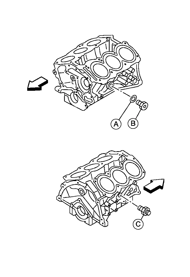
: Engine front

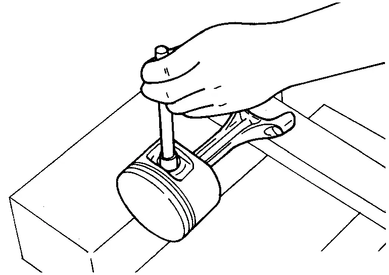
Remove the piston and connecting rod assemblies using the following procedure:Before removing the piston and connecting rod assembly, check the connecting rod side clearance. Refer to Cylinder Block. Position the crankshaft pin corresponding to the connecting rod to be removed onto the bottom dead center. Remove the connecting rod cap bolts and remove the connecting rod cap. Using a hammer handle or similar tool, push the piston and connecting rod assembly out to the cylinder head side.

Remove the connecting rod bearings.

Remove the piston rings from the piston using suitable tool (A).
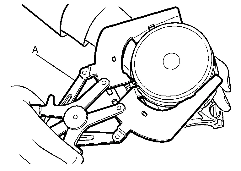
  • Before removing the piston rings, check the piston ring side clearance. Refer to Inspection.

  • Be careful to mark the rings if they are to be reused so they are installed in their original position.

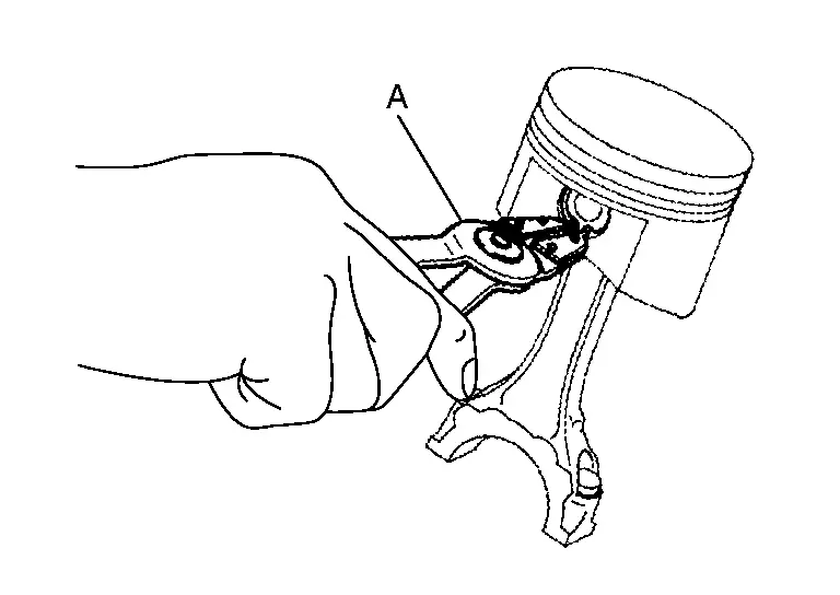
Remove the piston from the connecting rod as follows.Using suitable tool (A), remove the snap rings.
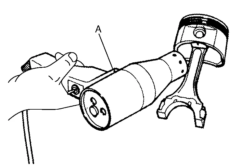
Heat the pistons to 60° - 70 °C using a suitable tool (A).
Push out the piston pin with a suitable tool with an outer diameter of approximately 20 mm (0.8 in).

Remove the baffle plate from the main bearing beam.

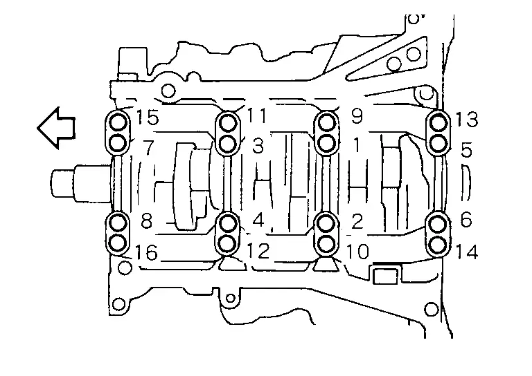
Loosen the bolts in reverse of the order shown and remove the main bearing beam, bearing caps and crankshaft.
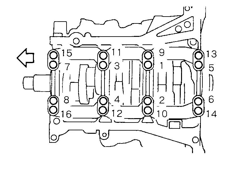
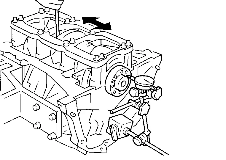
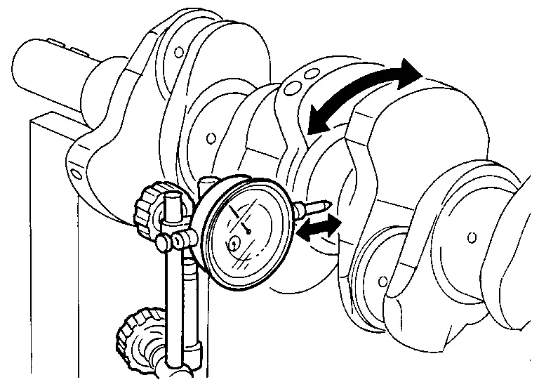
  • Before loosening the main bearing cap bolts, measure the crankshaft side clearance. Refer to Inspection.

    : Engine front

Remove the oil jets.

Remove the main bearings and thrust bearings from the cylinder block and main bearing caps.

  • When removing them, note the direction and position. Keep them in the correct order for installation.

ASSEMBLY

Blow out the engine coolant and engine oil passages and cylinder bore to remove any foreign materials.

Install the cylinder block drain plugs (if removed).

  • Apply sealant to the thread of the water drain plug (B), connector bolt (C).

    Use Genuine High Performance Thread Sealant or equivalent. Refer to Recommended Chemical Products and Sealants.

    Water drain plug (B) : 62 N·m
    Connector bolt (C) : 39 N·m
    : Engine front

Install the oil jets.

Install the main bearings and the thrust bearings.Remove dust, dirt, and engine oil on the bearing mating surfaces of the cylinder block and the main bearing cap. Install the thrust bearings (1) to both sides of the No. 3 journal housing (B) on the cylinder block and the main bearing cap.

  • Install the thrust bearings with the oil groove (E) facing the crankshaft arm (outside).

  • Install bearing with a projection on one end on cylinder block and bearing with a projection at center on cap. Align each projection with mating notch.

(A) : No. 4 journal housing
(C) : No. 2 journal housing
(D) : No. 1 journal housing
: Engine front

Set the upper main bearings in their proper positions on the cylinder block.

  • Confirm the correct main bearings are used. Refer to Inspection.

Instructions for the re-use of the main bearing cap bolts.
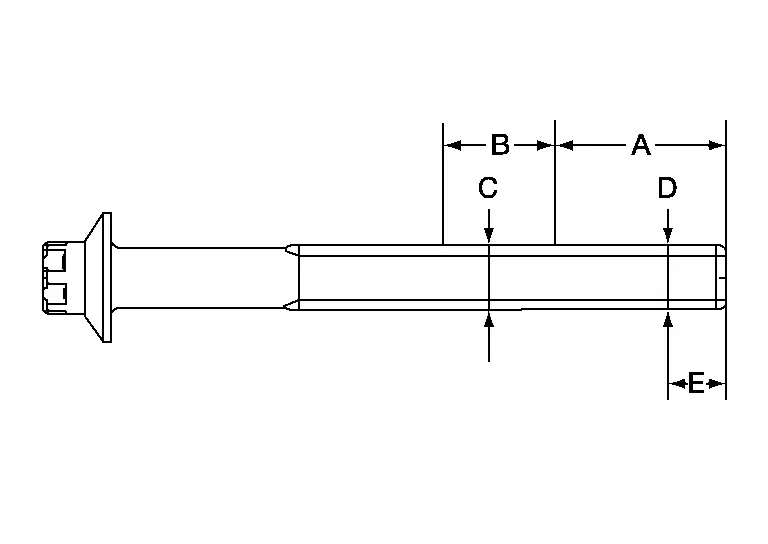
  • A plastic zone tightening method is used for tightening the main bearing cap bolts. Measure (D) and (C) as shown.

  • For (C), select the minimum diameter in the measuring area.

  • If the difference between (D) and (C) exceeds the limit, replace the bolts for assembly.

Limit [(D) - (C)] : 0.11 mm (0.0043 in)

(A) : 30 mm (1.18 in)
(B) : 20 mm (0.79 in)
(E) : 10 mm (0.39 in)

Install the crankshaft, lower main bearings, main bearing caps, main bearing beam, and bearing cap bolts using the following procedure:Make sure that the front marks on the main bearing beam faces the front of the engine.
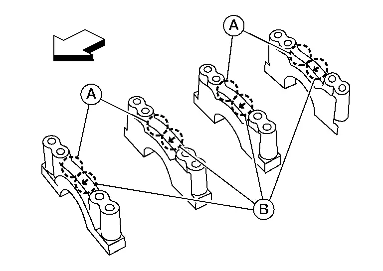
(A) : Main bearing journal number
(B) : Front mark
: Engine front

Prior to tightening all the bearing cap bolts, place the bearing beam in its proper position by shifting the crankshaft in the axial position. Tighten the main bearing cap bolts to the specified torque and specified angle in the sequence shown.

Step 1 : 44 N·m
Step 2 : 90° – 95° degrees clockwise

Tool number : KV10112100 (BT-8653-A)

After tightening the bearing cap bolts, make sure the crankshaft turns smoothly.

Measure crankshaft end play.

  • If beyond the limit, replace the thrust bearing with a new one.

Standard and Limit : Refer to Cylinder Block.

Install the piston to the connecting rod.Using suitable snap ring pliers, install the snap ring fully into the pin-groove of the piston rear side.

(A) : Piston front mark
(B) : Oil hole
(C) : Connecting rod front mark
(D) : Cylinder No.

Install the piston to the connecting rod.
  • Heat the piston until the piston pin can be pushed in by hand without excessive force [approx. 60 - 70 °C]. From the front to the rear, insert the piston pin into the piston and through the connecting rod.

  • Assemble so that the piston front mark (B) on the crown and the oil hole (C), connecting rod front mark (D) and Cylinder No. (E) on the connecting rod are positioned as shown.
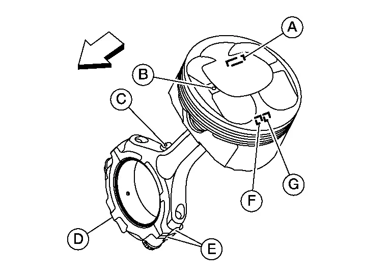
    (A) : Crown ID code
    (F) : Piston grade number
    (G) : Piston type (RH or LH)
    : Engine front
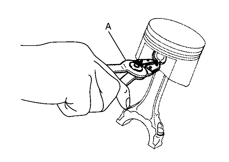
Install the snap ring into the front of the piston pin-groove using suitable tool (A).
  • After installing, check that the connecting rod pivots smoothly on the pin.

Using a piston ring expander, install the piston rings.
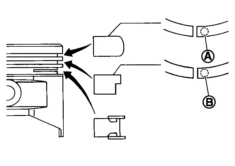
(A) : No marking
(B) : Z4

  • Position each ring with the gap as shown, referring to the piston front mark (E).
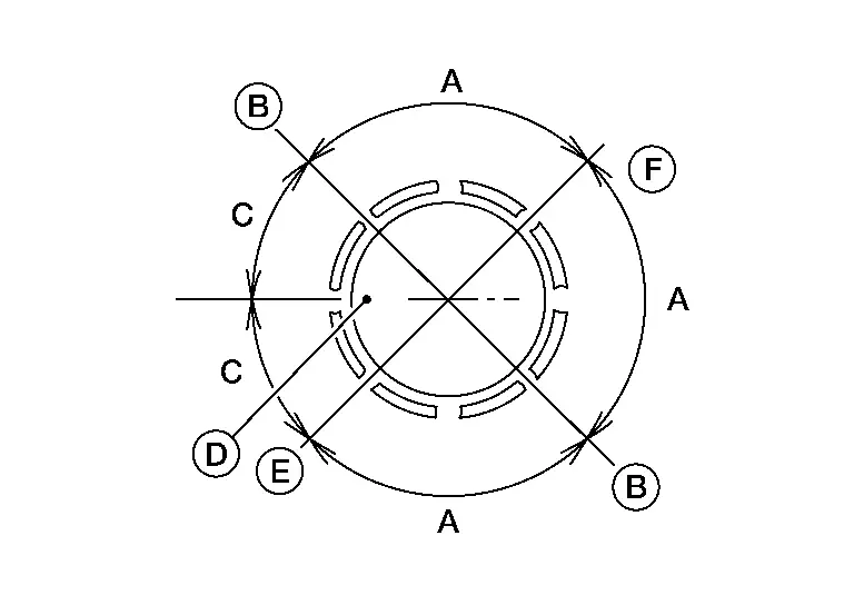
    (A) : 90°
    (B) : Oil ring upper or lower rail gap (either of them)
    (C) : 45°
    (D) : Piston front mark
    (E) : Second ring gap
    (F) : Top ring gap

Install the connecting rod bearings to the connecting rod and the connecting rod cap.

  • When installing the connecting rod bearings, apply engine oil to the bearing surface (crankshaft side). Do not apply engine oil to the back surface (connecting rod and cap side), but thoroughly clean it.

  • When installing, align the connecting rod bearing protrusion (A) with the notch (B) of the connecting rod to install.
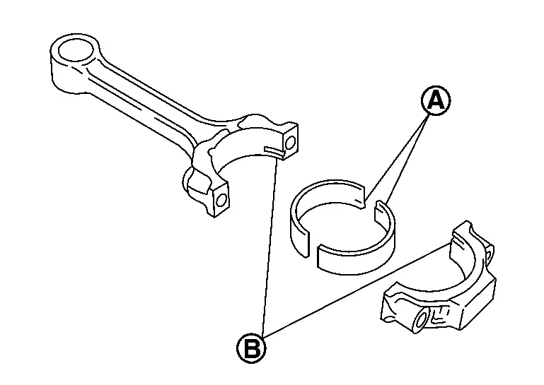
  • Check that the oil holes on the connecting rod and on the corresponding bearing are aligned.

Install the piston and connecting rod assembly into the corresponding cylinder.
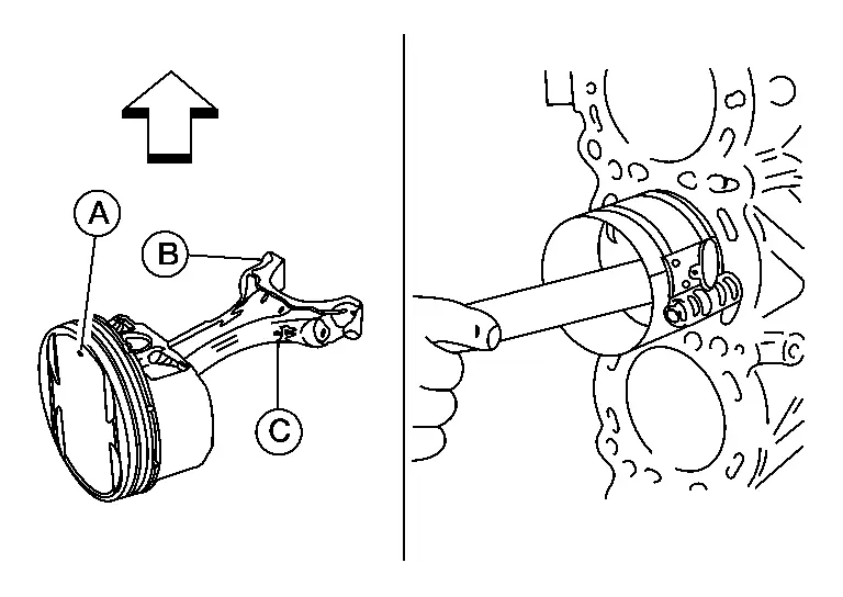
  • Position the crankshaft pin corresponding to the connecting rod to be installed onto the bottom dead center.

  • Apply engine oil sufficiently to the cylinder bore, piston skirt, piston ring, and crankshaft pin.

  • Match the cylinder position with the cylinder No. (B) on the connecting rod to install.

  • Install the piston with the piston front mark (A) on the crown facing the front of the engine ( ) using suitable tool.

    (C) : Oil hole

Install the connecting rod cap.
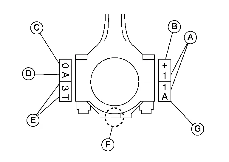
  • Match the stamped cylinder number marks (A) on the connecting rod with those on the cylinder cap for installation.

  • Install the piston connecting rod assembly and cap so that the front mark (F) on the cap and piston are facing the front of the engine.

  • Lubricate the threads and seat surfaces with new engine oil.

(B) : Stamping mark
(C) : Small end hole grade
(D) : Mass grade
(E) : Production control mark
(G) : Production control mark

Check the connecting rod cap bolts before reusing, then install in their original position in the connecting rod. The bolts should screw in smoothly by hand.
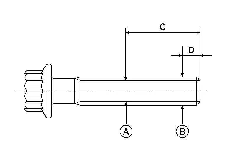
  • Measure the outer diameter of the connecting rod cap bolt as shown.

    Limit [(B) - (A)] : 0.12 mm (0.0047 in)

    (C) : 19 mm (0.75 in)
    (D) : 5 mm (0.20 in)

  • When reduction exceeds the limit (when it becomes thinner), replace with new connecting rod bolt.

Tighten the connecting rod bolts in two steps using Tool:
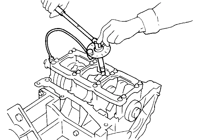
Step 1 : 19,6 N·m
Step 2 : 90° - 95° degrees clockwise

Tool number : KV10112100 (BT-8653-A)

  • After tightening the nuts, make sure that the crankshaft rotates smoothly.

  • Check the connecting rod side clearance. If beyond the limit, replace the connecting rod and/or crankshaft.

    Connecting rod side clearance:
    Standard and Limit : Refer to Cylinder Block.

Install the baffle plate to the main bearing beam.

Install the knock sensors.

  • Make sure that there is no foreign material on the cylinder block mating surface and the back surface of the knock sensor.

  • Install the bank 2 knock sensor (1) and then the bank 1 knock sensor (2).
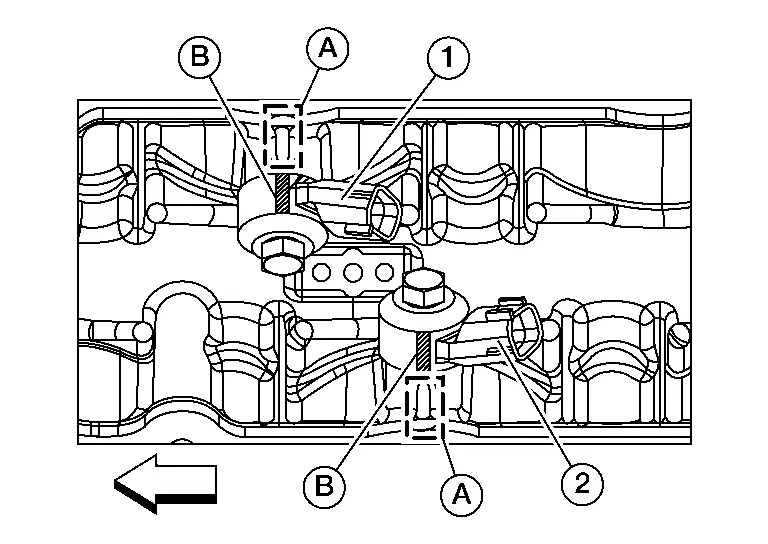
  • Align marking (B) on knock sensor with casting (A) on cylinder block.

  • Do not tighten the bolts while holding the connector.

  • Make sure that the knock sensor does not interfere with other parts.

Remove engine from the stand.

Install a new rear oil seal retainer using Tool (A).
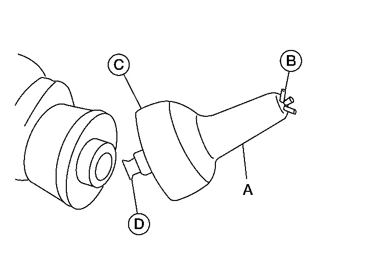
Tool number (A) : — (NI-47128)

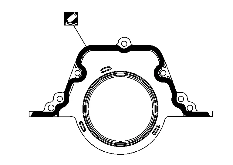
Loosen the wing nut (B) on the end of the Tool (A). Insert the arbor (D) into the crankshaft pilot hole until the outer lip (C) of the Tool (A) covers the edge of the crankshaft sealing surface. Tighten the wing nut (B) to secure the Tool (A) to the crankshaft. Apply sealant to rear oil seal retainer as shown.

Use Genuine Silicone RTV Sealant, or equivalent. Refer to Recommended Chemical Products and Sealants.

Lubricate the sealing surface of the new rear main seal with new engine oil. Slide the new rear main seal (1) over the Tool (A) and onto the crankshaft.
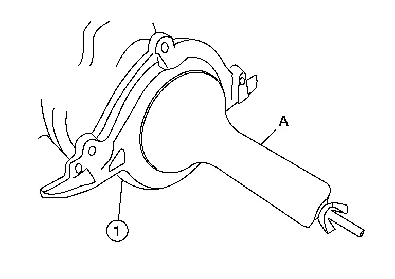
Loosen the wing nut and push the threaded rod into the handle to remove the Tool (A). Tighten the rear oil seal retainer bolts to specification. Refer to Removal and Installation of Rear Oil Seal.

Assembly of the remaining components is in the reverse order of disassembly.

Inspection

PISTON AND PISTON PIN CLEARANCE

Inner Diameter of Piston Pin Hole

  • Measure the inner diameter of piston pin hole using suitable tool (A).
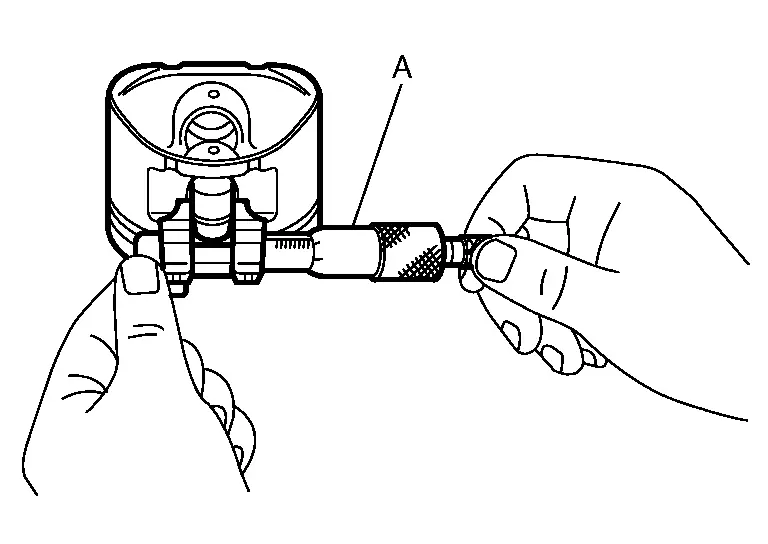
    Standard : Refer to Cylinder Block.

Outer Diameter of Piston Pin

  • Measure outer diameter of piston pin using suitable tool (A).
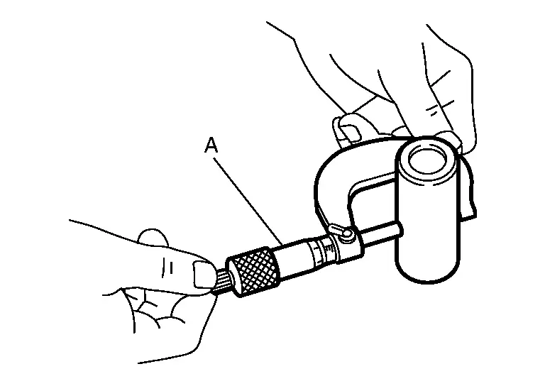
    Standard : Refer to Cylinder Block.

Piston and Piston Pin Interference Fit

(Piston to piston pin oil clearance) = (Piston pin hole diameter) - (Piston pin outer diameter)

Standard : Refer to Cylinder Block.
  • If clearance is exceeds specification, replace either or both of piston/piston pin assembly and connecting rod assembly with reference to specification of each part.

PISTON RING SIDE CLEARANCE

  • Measure side clearance of piston ring and piston ring groove using suitable tool (C).

Standard and Limit : Refer to Cylinder Block.
(A) : OK
(B) : NG
  • If out of specification, replace piston ring assembly. If clearance exceeds maximum limit with new rings, replace piston.

PISTON RING END GAP

  • Using piston (1), insert (A) piston ring (2) until it is in the middle of the cylinder bore and measure the end gap using suitable tool (B).
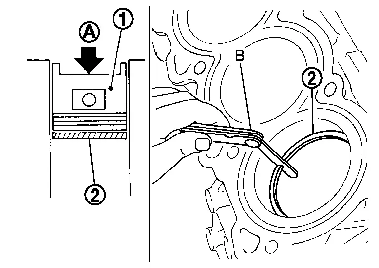
Standard and Limit : Refer to Cylinder Block.
  • If measured value exceeds limit replace piston ring and measure again. If it still exceeds the limit replace cylinder block.

CONNECTING ROD BEND AND TORSION

  • Check with a connecting rod aligner.

    Limit : Refer to Cylinder Block.
  • If it exceeds the limit, replace connecting rod assembly.

CONNECTING ROD BEARING HOUSING DIAMETER (BIG END)

  • Install the connecting rod cap (1) without the connecting rod bearing installed and tighten the connecting rod bolts. Refer to Disassembly and Assembly.
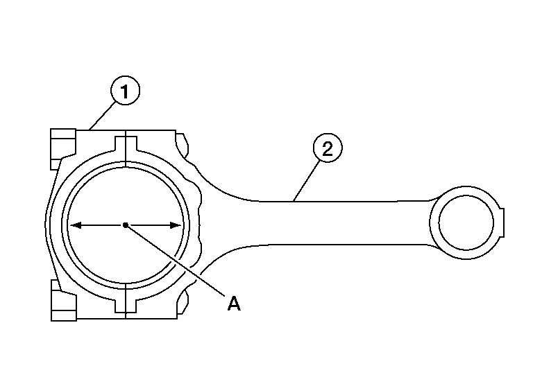
    (2) : Connecting rod
    (A) : Measuring direction of inner diameter
  • Measure inner diameter of connecting rod (big end) using a suitable tool.

    Standard : Refer to Cylinder Block.
  • If it exceeds the standard, replace connecting rod assembly.

CONNECTING ROD BUSHING OIL CLEARANCE (SMALL END)

Inner Diameter of Connecting Rod (Small End)

  • Measure inner diameter of piston pin bushing using suitable tool (A).
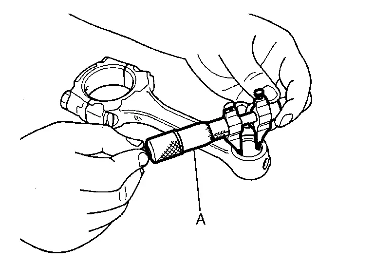
    Standard : Refer to Cylinder Block.

Outer Diameter of Piston Pin

  • Measure outer diameter of piston pin using suitable tool (A).
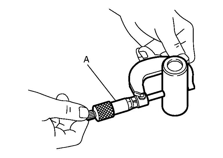
    Standard : Refer to Cylinder Block.

Connecting Rod Bushing Oil Clearance (Small End)

(Connecting rod small end oil clearance) = (Inner diameter of connecting rod small end) – (Outer diameter of piston pin)

Standard and Limit : Refer to Cylinder Block.
  • If the measured value exceeds the standard, replace the connecting rod assembly and/or piston and piston pin assembly.

  • If replacing the piston and piston pin assembly, use the Table for Selective Fitting for Piston to select the piston corresponding to the applicable bore grade of the cylinder block to be used. Follow the "PISTON-TO-CYLINDER BORE CLEARANCE" procedure.

CYLINDER BLOCK DISTORTION

  • Using a suitable tool, remove any old gasket material on the cylinder block surface and remove any engine oil, scale, carbon, or other contamination.

  • Measure distortion on cylinder block upper face at some different points in six directions using suitable tools (A/B).
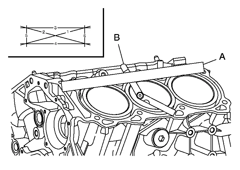
Limit : Refer to Cylinder Block.
  • If out of specification, resurface the cylinder block. The allowable amount of resurfacing is dependent on the amount of any cylinder head resurfacing. The resurfacing limit is [amount of cylinder head resurfacing] + [amount of cylinder block resurfacing] = 0.2 mm (0.008 in).

    Cylinder block height : 214.95 - 215.05 mm (8.4626 - 8.4665 in)

INNER DIAMETER OF MAIN BEARING HOUSING

  • Install the main bearing caps with the main bearings removed, and tighten the bolts to the specified torque.

  • Using suitable tool, measure the inner diameter (A) of the main bearing housing.
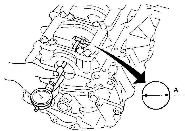
Standard : Refer to Cylinder Block.
  • If out of the standard, replace the cylinder block and main bearing caps as an assembly.

PISTON-TO-CYLINDER BORE CLEARANCE

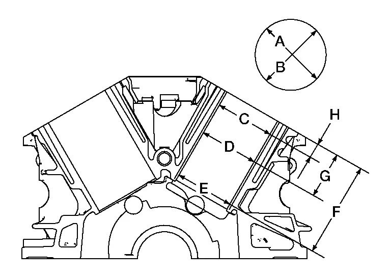
Using suitable tool, measure cylinder bore for wear, out-of-round and taper at (C), (D) and (E). The (A) axis is in the longitudinal direction of the engine.
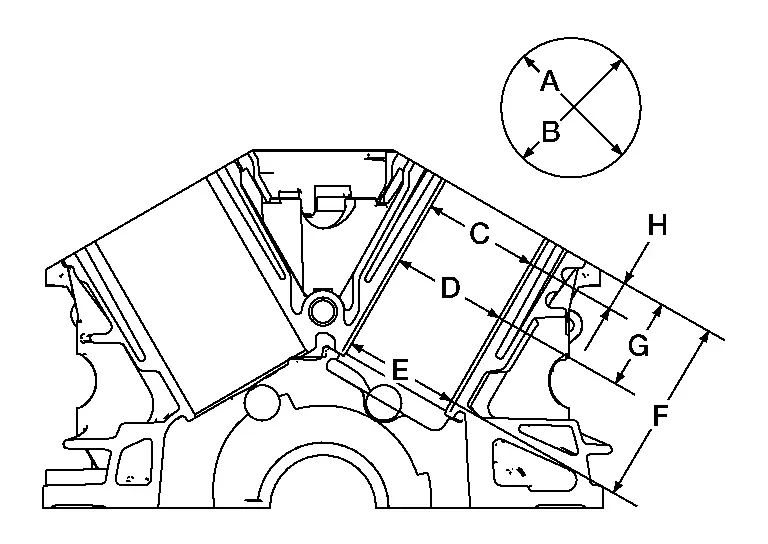
Out-of-round [Difference between (A) and (B)]
Limit : Refer to Cylinder Block.
Taper [Difference between (C), (D) and (E) in direction (A)]
Limit : Refer to Cylinder Block.

(F) : 120 mm (4.72 in)
(G) : 60 mm (2.36 in)
(H) : 10 mm (0.39 in)

If it exceeds the limit, rebore all cylinders. Replace cylinder block if necessary.

Check for scratches or other damage. If scratches or damage found, hone it.

  • If both cylinder block and piston are replaced with new ones, select piston of the same grade number punched on cylinder block rear position. These numbers are punched in either Arabic or Roman numerals.
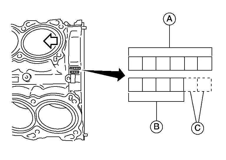
    (A) : Cylinder bore grade
    (B) : Main journal grade
    (C) : Management code
    : Engine front

Measure piston skirt diameter, using suitable tool.
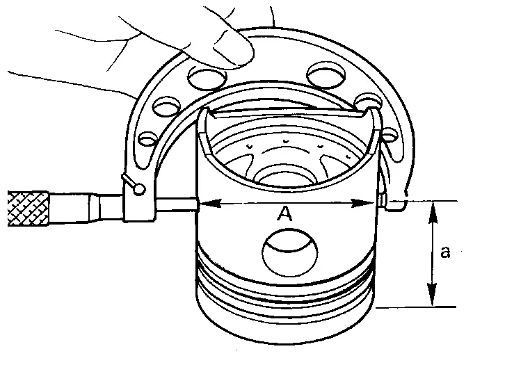
Piston diameter (A) : Refer to Cylinder Block.
Measuring point (a) (Distance from the top) : 38.0 mm (1.496 in)

Check that piston-to-bore clearance is within specification.

  • Calculate by piston skirt diameter and cylinder bore inner diameter [direction (B), position (D)].
    (Clearance) = (Cylinder bore inner diameter) – (Piston skirt diameter)
    Standard : Refer to Cylinder Block.

    (A) : Used for measuring cylinder bore out-of-round
    (C) : Used for measuring cylinder bore taper
    (E) : Used for measuring cylinder bore taper
    (F) : 120 mm (4.72 in)
    (G) : 60 mm (2.36 in)
    (H) : 10 mm (0.39 in)

Re-boring Cylinder Bore

Cylinder bore size is determined by adding piston-to-bore clearance to piston diameter.

Rebored size calculation : D = A + B − C
where,
(D) : Bored diameter
(A) : Piston diameter as measured
(B) : Piston-to-bore clearance
(C) : Honing allowance 0.02 mm (0.0008 in)

Install main bearing caps and main bearing beam, and tighten to the specified torque. Otherwise, cylinder bores may be distorted after boring. Refer to Exploded View.

Cut cylinder bores.

  • When any cylinder needs boring, all other cylinders must also be bored.

  • Do not cut too much out of cylinder bore at a time. Cut only 0.05 mm (0.0020 in) or so in diameter at a time.

Hone cylinders to obtain specified piston-to-bore clearance.

Measure finished cylinder bore for out-of-round and taper.

  • Measurement should be done after cylinder bore cools down.

CRANKSHAFT

Check the crankshaft main and pin journals for scoring, wear, or cracks.

Measure the journals for taper and out-of-round.

Standard
Out-of-round [(X) — (Y)] : Refer to Cylinder Block.
Taper [(A) - (B)] : Refer to Cylinder Block.

Measure crankshaft runout.

Place a V-block on a precise flat table to support the journals on the both ends of the crankshaft. Place a dial gauge straight up on the No. 3 journal. While rotating the crankshaft, read the movement of the pointer on the dial gauge.

Runout (total indicator reading)
Standard and Limit : Refer to Cylinder Block.

BEARING CLEARANCE

  • Use either of the following two methods, however method (A) gives more reliable results and so is the preferred method.

Method A (Using Bore Gauge and Micrometer)

Main Bearing

Set the main bearings in their proper positions on the cylinder block and the main bearing cap.

Install the main bearing caps and bearing beam to the cylinder block. Tighten all bolts to the specified torque in the sequence shown. Refer to Disassembly and Assembly.

Measure the inner diameters (A) of each main bearing as shown.
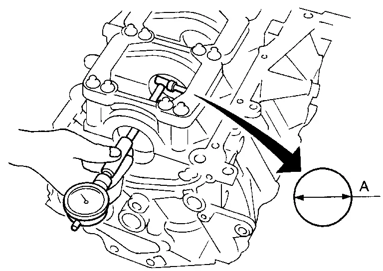
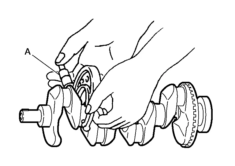
Using suitable tool (A), measure the outer diameters of each crankshaft main journal as shown.
Calculate the main bearing clearance.

Main bearing clearance = (Main bearing inner diameter) - (Crankshaft journal diameter)

Standard and Limit : Refer to Main Bearing.

  • If it exceeds the limit, replace the main bearing.

  • If clearance cannot be adjusted using any standard bearing grade, grind crankshaft journal and use an undersized bearing.

  • When grinding the crankshaft journal, confirm that the (L) dimension in the fillet role is more than the specified limit.

    Limit : Refer to Cylinder Block.

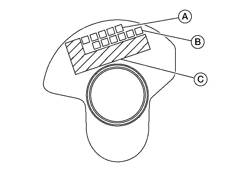
If the crankshaft or the cylinder block is replaced with a new one, select thickness of the main bearings as follows:The grade number of each cylinder block main journal (B) is punched on the respective cylinder block. These numbers are punched in either Arabic or Roman numerals. If measured diameter is out of the grade punched, decide suitable grade from available main bearings.

(A) : Cylinder bore grade
(C) : Management code
: Engine front

The grade number of each crankshaft main journal (A) is punched on the crankshaft end. These numbers are punched in either Arabic or Roman numerals. If measured diameter is out of grade punched, decide the suitable grade from available main bearings.

(B) : Crankshaft pin journal grade
(C) : Production mark area

Select the main bearing suitable thickness according to the following table:

(A) : Mark
(B) : Cylinder block bearing housing inner diameter
(C) : Crankshaft main journal diameter
(D) : Journal diameter [Unit: mm (in)]
(E) : Bore diameter [Unit: mm (in)]

Connecting Rod Bearing (Big End)

Install connecting rod bearings (2) to connecting rod (3) and connecting rod bearings cap (1) and tighten connecting rod bolts. Refer to Disassembly and Assembly.
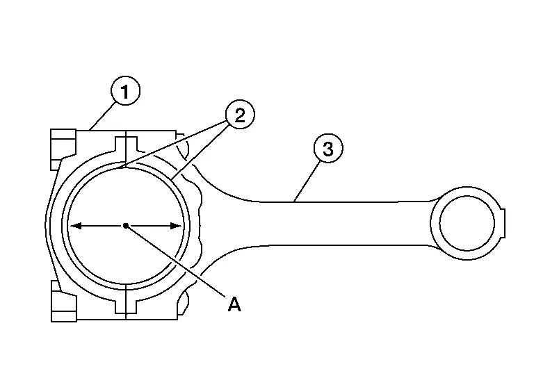
Measure the inner diameter (A) of each connecting rod (big end) as shown.

Using suitable tool (A), measure the outer diameter of each crankshaft pin journal.

Calculate the connecting rod bearing clearance.

(Bearing oil clearance) = (Connecting rod bearing inner diameter) - (Crankshaft pin journal diameter)

Standard and Limit : Refer to Connecting Rod Bearing.

If the calculated clearance exceeds the specified limit, replace the bearings.

If the clearance cannot be adjusted within the standard of any bearing, grind the crankshaft journal and use undersized bearings.

If the crankshaft is replaced with a new one, select the connecting rod bearings according to the following table:
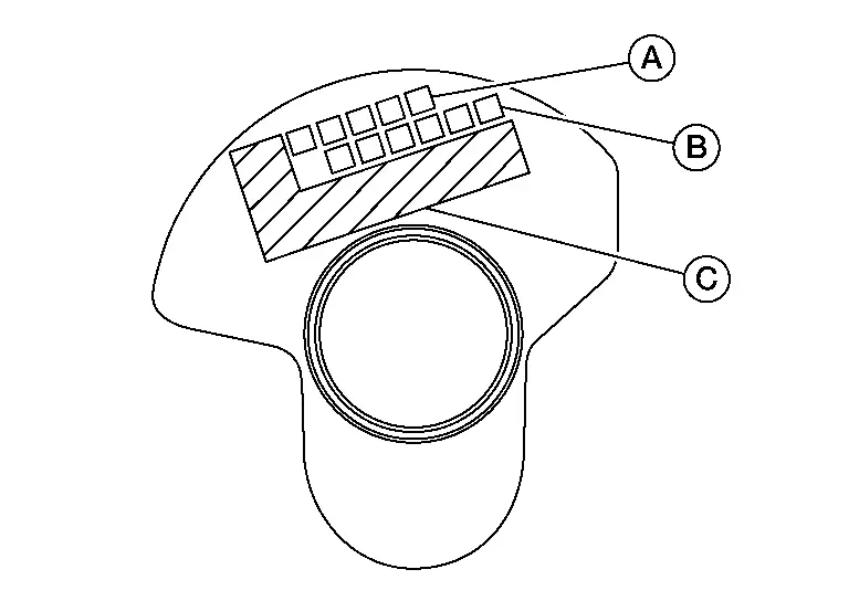
(A) : Crankshaft main journal grade
(B) : Crankshaft pin journal grade
(C) : Production mark area

Connecting Rod Bearing Grade Number (Identification Color)

  1. 0 (black-black)
  2. 1 (brown-brown)
  3. 2 (green-green)

These numbers are punched in either Arabic or Roman numerals.

Method B (Using Plastigage)

  • Remove engine oil and dust on the crankshaft pin and the surfaces of each bearing completely.

  • Cut a Plastigage slightly shorter than the bearing width, and place it in crankshaft axial direction, avoiding oil holes.

  • Install the connecting rod bearings to the connecting rod cap, and tighten the connecting rod bolts to the specified torque. Refer to Disassembly and Assembly.

  • Remove the connecting rod cap and bearings, and using the scale on the Plastigage bag, measure the Plastigage width.

OIL JET

  • Check nozzle for deformation and damage.

  • Blow compressed air from nozzle, and check for clogs.

  • If it is not operating properly, replace oil jet.