Body Exterior, Doors, Roof & Vehicle Security :: Door & Lock

Ecu Diagnosis Information - Intelligent Key Unit ++

In this manual: Body Exterior, Doors, Roof & Vehicle Security :: Door & Lock
General Information — 8Engine :: Engine Mechanical — 19Engine Lubrication System - Precautions. Preparation — 1Engine Lubrication System - Lubrication System (System Description). Engine Oil Pressure (Basic Inspection). Service Data and Specifications (SDS) — 1Engine Cooling System - Precautions. Preparation. Service Data and Specifications (SDS) — 1Engine Cooling System - Engine Coolant — 1Engine Control System - System Description — 1System Description - Component Parts ++ — 1System Description - System ++ — 1Engine Control System - Ecu Diagnosis Information — 1Ecu Diagnosis Information - Ecm ++ — 1Engine Control System - Basic Inspection — 1Basic Inspection - Diagnosis and Repair Workflow ++ — 1Basic Inspection - Basic Inspection ++ — 1Basic Inspection - Additional Service When Replacing Ecm ++ — 1Basic Inspection - Fuel Pressure Check ++ — 1Basic Inspection - How to Set Srt Code ++ — 1Basic Inspection - How to Erase Permanent Dtc ++ — 1Engine Control System - Dtc/circuit Diagnosis — 1Engine Control System - Symptom Diagnosis — 1Engine Control System - Periodic Maintenance — 1Engine Control System - Removal and Installation — 1Fuel System - Precautions. Preparation. Service Data and Specifications (SDS) — 1Fuel System - Fuel System (Periodic Maintenance). Fuel Level Sensor Unit (Disassembly and Assembly) — 1Exhaust System - Precautions. Preparation — 1Exhaust System - Exhaust System (Periodic Maintenance). Exhaust System (Removal and Installation) — 1Starting System - Precautions. Preparation. Starter Motor (Service Data and Specifications (sds)) — 1Starting System - Diagnosis and Repair Work Flow — 1Starting System - Starting System (Symptom Diagnosis). Starter Motor (Removal and Installation) — 1Accelerator Control System - Precautions. Service Data and Specifications (SDS) — 1Accelerator Control System - Accelerator Pedal Assembly — 1Transmission & Driveline :: Transaxle & Transmission — 21Driveline - System Description — 1Transfer: Ty92b - Ecu Diagnosis Information. Awd Control Unit ++ — 1Driveline - Basic Inspection — 1Driveline - Dtc/circuit Diagnosis — 1Driveline - Symptom Diagnosis — 1Driveline - Removal and Installation — 1Transfer: Ty92b - Unit Removal and Installation. Transfer Assembly ++ — 1Driveline - Unit Disassembly and Assembly — 1Driveline - Basic Inspection — 1Driveline - Removal and Installation — 1Driveline - Unit Disassembly and Assembly — 1Front Axle - Precautions. Preparation — 1Front Axle - Noise, Vibration and Harshness (nvh) Troubleshooting (Symptom Diagnosis). Service Data and Specifications (SDS) — 1Front Axle - Front Drive Shaft Boot — 1Front Axle - Front Drive Shaft — 1Rear Axle - Precautions. Preparation. Service Data and Specifications (SDS) — 1Rear Axle - Noise, Vibration and Harshness (nvh) Troubleshooting — 1Rear Axle - Rear Drive Shaft — 1Suspension :: Front Suspension — 7Rear Suspension - Precautions. Preparation — 1Rear Suspension - Noise, Vibration and Harshness (nvh) Troubleshooting (Symptom Diagnosis). Service Data and Specifications (SDS) — 1Rear Suspension - Rear Suspension Assembly — 1Road Wheels & Tires - Precautions — 1Road Wheels & Tires - Preparation. Bcm (Ecu Diagnosis Information). Service Data and Specifications (SDS) — 1Road Wheels & Tires - System — 1Brakes :: Brake System — 9Parking Brake System - Precautions. Preparation — 1Parking Brake System - System — 1Vdc/tcs/abs - Precautions ++ — 1Brake Control System - System Description — 1System Description - Component Parts ++ — 1System Description - System ++ — 1Brake Control System - Basic Inspection — 1Brake Control System - Symptom Diagnosis — 1Brake Control System - Removal and Installation — 1Brake Control System - System Description — 1Brake Control System - Dtc/circuit Diagnosis — 1Brake Control System - Removal and Installation — 1Brake Control System - System Description — 1Brake Control System - Basic Inspection — 1Brake Control System - Symptom Diagnosis — 1Brake Control System - System Description — 1Brake Control System - Basic Inspection — 1Brake Control System - Symptom Diagnosis — 1Steering :: Steering System — 9Steering Control System - Precautions — 1Steering Control System - System — 1Steering Control System - Eps Control Unit (Ecu Diagnosis Information. Removal and Installation) — 1Restraints :: Seat Belt — 7Srs Air Bag - Precautions. Preparation — 1Srs Air Bag - Collision Diagnosis — 1Srs Air Bag - Occupant Classification System — 1Srs Air Bag Control System - Precautions — 1Srs Air Bag Control System - System — 1Srs Air Bag Control System - Diagnosis Sensor Unit — 1Srs Air Bag Control System - Inspection and Adjustment — 1Ventilation, Heater & Air Conditioner :: Ventilation System — 6Heater & Air Conditioning System - Precautions — 1Heater & Air Conditioning System - Preparation — 1Heater & Air Conditioning System - Component Parts — 1Heater & Air Conditioning System - Diagnosis and Repair Work Flow — 1Heater & Air Conditioning System - Compressor — 1Heater & Air Conditioning System - Cooler Pipe and Hose — 1Heater & Air Conditioning System - Condenser. Condenser — 1Heater & Air Conditioning System - Heating and Cooling Unit Assembly — 1Heater & Air Conditioning System - Service Data and Specifications (SDS) — 1Heater & Air Conditioning Control System - System Description — 1System Description - Component Parts ++ — 1System Description - System ++ — 1System Description - Operation ++ — 1Heater & Air Conditioning Control System - Ecu Diagnosis Information — 1Heater & Air Conditioning Control System - Basic Inspection — 1Heater & Air Conditioning Control System - Dtc/circuit Diagnosis — 1Heater & Air Conditioning Control System - Symptom Diagnosis — 1Heater & Air Conditioning Control System - Removal and Installation — 1Body Interior :: Interior — 8Instrument Panel - Precautions. Preparation. Clip List — 1Instrument Panel - Squeak and Rattle Trouble Diagnoses — 1Instrument Panel - Cluster Lid C — 1Seat - Precautions — 1Seat - Preparation. Clip List — 1Seat - Component Parts — 1Seat - System — 1Seat - Diagnosis and Repair Work Flow — 1Seat - Front Seat — 1Seat - Second Row Seats — 1Seat - Third Row Seats — 1Seat - Front Seat — 1Seat - Second Row Seat — 1Seat - Third Row Seat — 1Automatic Drive Positioner - Precautions. Preparation — 1Automatic Drive Positioner - System — 1Automatic Drive Positioner - Diagnosis and Repair Work Flow — 1Automatic Drive Positioner - Inspection and Adjustment — 1Body Exterior, Doors, Roof & Vehicle Security :: Door & Lock — 38Security Control System - Precautions — 1Security Control System - System — 1Security Control System - Ecm, Bcm, Intelligent Key Unit, Ipdm E/r — 1Security Control System - Vehicle Security System Cannot Be Set — 1Glass & Window System - Precautions. Preparation — 1Glass & Window System - Squeak and Rattle Trouble Diagnoses — 1Power Window Control System - Precautions. Preparation — 1Power Window Control System - Power Supply and Ground Circuit — 1Power Window Control System - Power Window Motor Circuit — 1Power Window Control System - Front Power Window Rh Alone Does Not Operate — 1Power Window Control System - Rear Lh Side Power Window Alone Does Not Operate — 1Power Window Control System - Rear Rh Side Power Window Alone Does Not Operate — 1Roof - Precautions. Preparation — 1Roof - Power Supply and Ground Circuit — 1Roof - Moonroof Switch Assembly — 1Roof - Lin Communication Circuit — 1Roof - Auto Operation Does Not Operate — 1Roof - Anti-Pinch Function Does Not Operate — 1Exterior - Precautions. Preparation. Clip List (Preparation) — 1Exterior - Squeak and Rattle Trouble Diagnoses — 1Exterior - Fender Protector — 1Exterior - Over Fender — 1Exterior - Under Cover — 1Exterior - Roof Side Rail — 1Body Repair - Service Information — 1Service Information - Sheet Metal Work ++ — 1Service Information - Body Welding and Precautions ++ — 1Service Information - Safety and Health ++ — 1Service Information - Repairing Procedures and Precautions ++ — 1Body Repair - Precaution — 1Body Repair - Preparation — 1Body Repair - Removal and Installation — 1Driver Controls :: Mirrors — 8Exterior Lighting System - System Description — 1System Description - Component Parts ++ — 1Exterior Lighting System - Basic Inspection — 1Exterior Lighting System - Dtc/circuit Diagnosis — 1Exterior Lighting System - Symptom Diagnosis — 1Exterior Lighting System - Periodic Maintenance — 1Exterior Lighting System - Removal and Installation — 1Interior Lighting System - Precautions. Preparation — 1Interior Lighting System - Component Parts. Interior Lighting System — 1Interior Lighting System - System — 1Interior Lighting System - Diagnosis and Repair Work Flow — 1Interior Lighting System - Interior Lighting System Symptoms (Symptom Diagnosis). Bcm (Ecu Diagnosis Information). Service Data and Specifications (SDS) — 1Interior Lighting System - Foot Lamp — 1Wiper & Washer - Precautions — 1Wiper & Washer - Preparation. Bcm, Ipdm E/r (Ecu Diagnosis Information). Service Data and Specifications (SDS) — 1Wiper & Washer - System — 1Wiper & Washer - Diagnosis and Repair Work Flow — 1Defogger - Precautions. Bcm, A/c Auto Amp. (Ecu Diagnosis Information) — 1Defogger - Diagnosis and Repair Work Flow — 1Horn - Precautions — 1Electrical & Power Control :: Power Outlet — 13Body Control System - Precautions. Preparation — 1Body Control System - Component Parts — 1Body Control System - System — 1Body Control System - Diagnosis System (bcm) — 1Body Control System - Bcm — 1Lan System - System Description — 1Lan System - System Description — 1Lan System - Dtc/circuit Diagnosis — 1Lan System - System Description — 1Lan System - Dtc/circuit Diagnosis — 1Power Control System - System Description — 1Power Control System - Basic Inspection — 1Power Control System - Dtc/circuit Diagnosis — 1Power Control System - System Description — 1Power Control System - Basic Inspection — 1Power Control System - Dtc/circuit Diagnosis — 1Power Control System - Removal and Installation — 1Charging System - Precautions. Preparation. Ecm, Ipdm E/r (Ecu Diagnosis Information) — 1Charging System - Diagnosis and Repair Work Flow — 1Charging System - Charging System (Symptom Diagnosis). Generator (Removal and Installation). Service Data and Specifications (SDS) — 1Power Supply, Ground & Circuit Elements - Precautions. Preparation. Service Data and Specifications (SDS) — 1Driver Information & Multimedia :: Meter, Warning Lamp & Indicator — 25Warning Chime System - Application Notice (How to Use This Manual). Precautions — 1Warning Chime System - System — 1Warning Chime System - Diagnosis System (combination Meter) — 1Warning Chime System - Bcm, Combination Meter (Ecu Diagnosis Information). Diagnosis and Repair Work Flow (Basic Inspection) — 1Sonar System - Precautions. Preparation — 1Sonar System - Sonar Control Unit — 1Dtc/circuit Diagnosis - B2720 Corner Sensor [rl] ++ — 1Audio, Visual & Navigation System - System Description — 1System Description - Component Parts ++ — 1System Description - System ++ — 1Audio, Visual & Navigation System - Ecu Diagnosis Information — 1Audio, Visual & Navigation System - Basic Inspection — 1Audio, Visual & Navigation System - Dtc/circuit Diagnosis — 1Dtc/circuit Diagnosis - Multi Av (av Control Unit) ++ — 1Audio, Visual & Navigation System - Symptom Diagnosis — 1Symptom Diagnosis - Multi Av System ++ — 1Audio, Visual & Navigation System - Removal and Installation — 1Audio, Visual & Navigation System - System Description — 1Audio, Visual & Navigation System - Ecu Diagnosis Information — 1Audio, Visual & Navigation System - Basic Inspection — 1Audio, Visual & Navigation System - Dtc/circuit Diagnosis — 1Audio, Visual & Navigation System - Symptom Diagnosis — 1Audio, Visual & Navigation System - Removal and Installation — 1Audio, Visual & Navigation System - System Description — 1Audio, Visual & Navigation System - Basic Inspection — 1Audio, Visual & Navigation System - Dtc/circuit Diagnosis — 1Audio, Visual & Navigation System - Symptom Diagnosis — 1Audio, Visual & Navigation System - Removal and Installation — 1Audio, Visual & Navigation System - System Description — 1Audio, Visual & Navigation System - Basic Inspection — 1Audio, Visual & Navigation System - Dtc/circuit Diagnosis — 1Audio, Visual & Navigation System - Symptom Diagnosis — 1Audio, Visual & Navigation System - Removal and Installation — 1Cruise Control & Driver Assistance :: Cruise Control System — 17Driver Assistance System - System Description — 1Driver Assistance System - Basic Inspection — 1Driver Assistance System - Dtc/circuit Diagnosis — 1Driver Assistance System - System Description — 1System Description - Component Parts ++ — 1System Description - System ++ — 1System Description - Operation ++ — 1System Description - Handling Precaution ++ — 1Driver Assistance System - Ecu Diagnosis Information — 1Driver Assistance System - Basic Inspection — 1Basic Inspection - Distance Sensor Alignment ++ — 1Basic Inspection - Camera Aiming Adjustment ++ — 1Basic Inspection - Action Test ++ — 1Driver Assistance System - Dtc/circuit Diagnosis — 1Dtc/circuit Diagnosis - Laser/radar (distance Sensor) ++ — 1Dtc/circuit Diagnosis - Lane Camera (front Camera Unit) ++ — 1Driver Assistance System - Symptom Diagnosis — 1Driver Assistance System - Removal and Installation — 1Driver Assistance System - System Description — 1System Description - System ++ — 1Driver Assistance System - Basic Inspection — 1Driver Assistance System - Dtc/circuit Diagnosis — 1Drive Mode System - Precautions — 1Drive Mode System - Component Parts. Drive Mode System — 1Drive Mode System - System — 1Drive Mode System - Diagnosis and Repair Work Flow — 1Drive Mode System - Drive Mode Select Switch Circuit — 1Maintenance - Precautions. Preparation — 1Maintenance - General Maintenance — 1Maintenance - Periodic Maintenance — 1Maintenance - Recommended Fluids and Lubricants — 1Maintenance - Engine Maintenance — 1Maintenance - Chassis and Body Maintenance — 1Engine Lubrication System - Periodic Maintenance — 1Engine Lubrication System - Removal and Installation — 1Engine Cooling System - System Description — 1Engine Cooling System - Removal and Installation — 1Engine Control System - Vq35dd — 1Fuel System - Removal and Installation — 1Starting System - System Description — 1Starting System - Dtc/circuit Diagnosis — 1Driveline - Transfer: Ty92b — 1Driveline - Rear Propeller Shaft: 3fcj-Cvj — 1Driveline - Rear Final Drive: R145 — 1Front Axle - Periodic Maintenance — 1Front Axle - Removal and Installation — 1Rear Axle - Periodic Maintenance — 1Rear Axle - Removal and Installation — 1Rear Suspension - Removal and Installation — 1Road Wheels & Tires - System Description — 1Road Wheels & Tires - Basic Inspection — 1Road Wheels & Tires - Dtc/circuit Diagnosis — 1Road Wheels & Tires - Symptom Diagnosis — 1Road Wheels & Tires - Periodic Maintenance — 1Road Wheels & Tires - Removal and Installation — 1Parking Brake System - System Description — 1Parking Brake System - Basic Inspection — 1Parking Brake System - Dtc/circuit Diagnosis — 1Parking Brake System - Symptom Diagnosis — 1Parking Brake System - Removal and Installation — 1Brake Control System - Vdc/tcs/abs — 1Brake Control System - Automatic Brake Hold — 1Brake Control System - Automatic Emergency Braking — 1Brake Control System - Rear Automatic Braking — 1Steering Control System - System Description — 1Steering Control System - Basic Inspection — 1Steering Control System - Dtc/circuit Diagnosis — 1Steering Control System - Symptom Diagnosis — 1Srs Air Bag - Removal and Installation — 1Srs Air Bag Control System - System Description — 1Srs Air Bag Control System - Basic Inspection — 1Srs Air Bag Control System - Symptom Diagnosis — 1Heater & Air Conditioning System - Symptom Diagnosis — 1Heater & Air Conditioning System - Periodic Maintenance — 1Heater & Air Conditioning Control System - Automatic Air Conditioning — 1Instrument Panel - Removal and Installation — 1Instrument Panel - Unit Disassembly and Assembly — 1Seat - Ecu Diagnosis Information — 1Seat - Dtc/circuit Diagnosis — 1Seat - Symptom Diagnosis — 1Automatic Drive Positioner - System Description — 1Automatic Drive Positioner - Ecu Diagnosis Information — 1Automatic Drive Positioner - Dtc/circuit Diagnosis — 1Automatic Drive Positioner - Symptom Diagnosis — 1Automatic Drive Positioner - Removal and Installation — 1Security Control System - System Description — 1Security Control System - Basic Inspection — 1Security Control System - Dtc/circuit Diagnosis — 1Security Control System - Symptom Diagnosis — 1Security Control System - Removal and Installation — 1Glass & Window System - Removal and Installation — 1Power Window Control System - System Description — 1Power Window Control System - Ecu Diagnosis Information — 1Power Window Control System - Basic Inspection — 1Power Window Control System - Dtc/circuit Diagnosis — 1Power Window Control System - Symptom Diagnosis — 1Power Window Control System - Removal and Installation — 1Roof - System Description — 1Roof - Ecu Diagnosis Information — 1Roof - Basic Inspection — 1Roof - Dtc/circuit Diagnosis — 1Roof - Symptom Diagnosis — 1Roof - Removal and Installation — 1Exterior - System Description — 1Exterior - Removal and Installation — 1Body Repair - Repair Information — 1Exterior Lighting System - Led Headlamp — 1Interior Lighting System - Dtc/circuit Diagnosis — 1Interior Lighting System - Removal and Installation — 1Wiper & Washer - System Description — 1Wiper & Washer - Dtc/circuit Diagnosis — 1Wiper & Washer - Symptom Diagnosis — 1Wiper & Washer - Removal and Installation — 1Defogger - System Description — 1Defogger - Dtc/circuit Diagnosis — 1Defogger - Symptom Diagnosis — 1Defogger - Removal and Installation — 1Horn - Removal and Installation — 1Body Control System - Basic Inspection — 1Body Control System - Dtc/circuit Diagnosis — 1Body Control System - Symptom Diagnosis — 1Body Control System - Removal and Installation — 1Lan System - Can Fundamental — 1Lan System - Can — 1Lan System - Can Gateway — 1Power Control System - Ipdm E/r — 1Power Control System - Power Distribution System — 1Charging System - System Description — 1Charging System - Dtc/circuit Diagnosis — 1Power Supply, Ground & Circuit Elements - System Description — 1Power Supply, Ground & Circuit Elements - Basic Inspection — 1Power Supply, Ground & Circuit Elements - Removal and Installation — 1Warning Chime System - System Description — 1Warning Chime System - Dtc/circuit Diagnosis — 1Warning Chime System - Symptom Diagnosis — 1Sonar System - System Description — 1Sonar System - Basic Inspection — 1Sonar System - Dtc/circuit Diagnosis — 1Sonar System - Symptom Diagnosis — 1Sonar System - Removal and Installation — 1Audio, Visual & Navigation System - Nissanconnect — 1Audio, Visual & Navigation System - Intelligent Around View Monitor System — 1Audio, Visual & Navigation System - Rear View Monitor System — 1Audio, Visual & Navigation System - Telematics System — 1Driver Assistance System - Adas Control Unit 2 — 1Driver Assistance System - Driver Assistance System — 1Driver Assistance System - Chassis Control — 1Drive Mode System - Removal and Installation — 1Dtc/circuit Diagnosis (C053c Wheel Speed Sensor ... U2141 Can Comm Circuit) — 1Dtc/circuit Diagnosis (P0011 Intake Valve Timing Control ... P0111 Iat Sensor) — 1Dtc/circuit Diagnosis (P0116 Engine Coolant Temperature Sensor ... P025b Fuel Pump Module a) — 1Dtc/circuit Diagnosis (P026b Injection Timing ... P0420 Three Way Catalyst Function) — 1Dtc/circuit Diagnosis (P0441 Evap Control System ... P0524 Engine Oil Pressure) — 1Dtc/circuit Diagnosis (P0532 A/c Refrigerant Pressure Sensor ... P064d Ecm) — 1Dtc/circuit Diagnosis (P06da Engine Oil Pressure Control Solenoid Valve ... P1217 Engine Over Temperature) — 1Dtc/circuit Diagnosis (P1220 Fuel Pump Control Module (fpcm) ... P1574 Ascd Vehicle Speed Sensor) — 1Dtc/circuit Diagnosis (P1575 Brake Switch ... P2101 Electric Throttle Control Function) — 1Dtc/circuit Diagnosis (P2118 Throttle Control Motor ... P34ac Electric Intake Valve Timing Control Actuator) — 1Dtc/circuit Diagnosis (Active Grille Shutter ... High Pressure Fuel Pump) — 1Dtc/circuit Diagnosis (Ignition Signal ... Variable Induction Air System) — 14012 C1040 Emergency Brake — 14013 C106a Wheel Sensor — 14014 C1078-55 Not Configuration — 14015 C10b4-98 Overheat — 14016 B1001 Lap Pre-Tensioner Lh — 14017 B0001 Driver Air Bag Module — 14018 B100e Knee Air Bag Module Rh — 14019 B142x Collision Detection — 1Dtc/circuit Diagnosis (B20c7-11 A/c Clutch ... B24a6-11 in-Vehicle Sensor) — 1Dtc/circuit Diagnosis (B24a6-15 in-Vehicle Sensor ... U2140-87 Can Comm Err (ecm)) — 1Dtc/circuit Diagnosis (C1f00-1c Control Unit ... C1f04-61 Brake Sw/stop Lamp Sw) — 1Dtc/circuit Diagnosis (C1f05-49 Front Camera Unit ... C1f70-87 Ethernet Circuit) — 1
6steps
~36min
2/5difficulty
Done 0 of 6

Reference Value

VALUES ON THE DIAGNOSIS TOOL

CONSULT MONITOR ITEM
Monitor Item Condition Value/Status
I-KEY unit blank status Intelligent Key unit is registered Off
Intelligent Key unit is not registered (blank status) On
I-KEY unit power supply status Intelligent Key unit power supply normally Off

Intelligent Key unit power supply malfunction

On
KEY ID1 Which pressing the door request switch carrying the Intelligent Key #1 On
Other than above Off
KEY ID2 Which pressing the door request switch carrying the Intelligent Key #2 On
Other than above Off
KEY ID3 Which pressing the door request switch carrying the Intelligent Key #3 On
Other than above Off
KEY ID4 Which pressing the door request switch carrying the Intelligent Key #4 On
Other than above Off
Battery voltage Ignition switch ON 10 – 16 V
IGN ON (IPDM E/R) Other than ignition switch ON Off
Ignition switch ON On
Nissan Pathfinder Vehicle speed (ABS) While driving Equivalent to speedometer reading
Nissan Pathfinder Vehicle speed (meter) While driving Equivalent to speedometer reading
Total distance While driving Indicates total Nissan Pathfinder vehicle distance
Keyfob button1 Other than below Off
  • Without remote engine start models and with automatic back door models: UNLOCK button is pressed

  • Except without remote engine start models and with automatic back door models: LOCK button is pressed

On
Keyfob button2 Other than below Off
  • Without remote engine start models and with automatic back door models: LOCK button is pressed

  • Except without remote engine start models and with automatic back door models: REMOTE ENGINE START button is pressed

On
Keyfob button3 Other than below Off
  • With remote engine start and without automatic back door models: UNLOCK button is pressed

  • With automatic back door models: POWER BACK DOOR button is pressed

On
Keyfob button4 Other than below Off
PANIC button is pressed On
BD/TR opener SW When back door opener switch circuit is malfunction Malf
When back door opener switch is not pressed Off
When back door opener switch is pressed On
Key ID (last) When any keyfob button is pressed 1,2,3,4
Keyfob#1 cabin area Other than below Off
When Intelligent Key #1 is in cabin area, press the door request switch carrying other Keyfob On
Keyfob#1 undefined area When Intelligent Key #1 is detected by multiple inside/ outside key antenna Off
When Intelligent Key #1 is out of range of the defined Intelligent Key unit area On
Keyfob#1 rear bumper area Other than below Off
When press the back door request switch carrying Intelligent Key #1 On
Keyfob#2 cabin area Other than below Off
When Intelligent Key #2 is in cabin area, press the door request switch carrying other Keyfob On
Keyfob#2 undefined area When Intelligent Key #2 is detected by multiple inside/ outside key antenna Off
When Intelligent Key #2 is out of range of the defined Intelligent Key unit area On
Keyfob#2 rear bumper area Other than below Off
When press the back door request switch carrying Intelligent Key #2 On
Keyfob#3 cabin area Other than below Off
When Intelligent Key #3 is in cabin area, press the door request switch carrying other Keyfob On
Keyfob#3 undefined area When Intelligent Key #3 is detected by multiple inside/ outside key antenna Off
When Intelligent Key #3 is out of range of the defined Intelligent Key unit area On
Keyfob#3 rear bumper area Other than below Off
When press the back door request switch carrying Intelligent Key #3 On
Keyfob#4 cabin area Other than below Off
When Intelligent Key #4 is in cabin area, press the door request switch carrying other Keyfob On
Keyfob#4 undefined area When Intelligent Key #4 is detected by multiple inside/ outside key antenna Off
When Intelligent Key #4 is out of range of the defined Intelligent Key unit area On
Keyfob#4 rear bumper area Other than below Off
When press the back door request switch carrying Intelligent Key #4 On
Keyfob button5 Other than below Off
With automatic back door models: REMOTE ENGINE START button is pressed On
Keyfob operation Keyfob button is not pressed Off
UNLOCK button is pressed Unlock
LOCK button is pressed Lock
Automatic back door button is pressed TR/BD
PANIC button is pressed Panic
ASD (RH)
ASD (LH)
Light
Remote engine start button is pressed Eng start
Roof
Push SW Push-button ignition switch (push-switch) is pressed Off
Push-button ignition switch (push-switch) is not pressed On
Request SW (FR) When front door request switch RH is not pressed Off
When front door request switch RH is pressed On
Request SW (FL) When front door request switch LH is not pressed Off
When front door request switch LH is pressed On
Request SW (BD) When back door request switch is not pressed Off
When back door request switch is pressed On
Registration Key ID status Intelligent Key is not registered Off
Intelligent Key is registered On
Keyfob#1 outside area (LH) When Intelligent Key #1 is out of range of outside key antenna (rear door LH) Off
When Intelligent Key #1 is in range of outside key antenna (rear door LH) On
Keyfob#1 outside area (RH) When Intelligent Key #1 is out of range of outside key antenna (rear door RH) Off
When Intelligent Key #1 is in range of outside key antenna (rear door RH) On
Keyfob#2 outside area (LH) When Intelligent Key #2 is out of range of outside key antenna (rear door LH) Off
When Intelligent Key #2 is in range of outside key antenna (rear door LH) On
Keyfob#2 outside area (RH) When Intelligent Key #2 is out of range of outside key antenna (rear door RH) Off
When Intelligent Key #2 is in range of outside key antenna (rear door RH) On
Keyfob#3 outside area (LH) When Intelligent Key #3 is out of range of outside key antenna (rear door LH) Off
When Intelligent Key #3 is in range of outside key antenna (rear door LH) On
Keyfob#3 outside area (RH) When Intelligent Key #3 is out of range of outside key antenna (rear door RH) Off
When Intelligent Key #3 is in range of outside key antenna (rear door RH) On
Keyfob#4 outside area (LH) When Intelligent Key #4 is out of range of outside key antenna (rear door LH) Off
When Intelligent Key #4 is in range of outside key antenna (rear door LH) On
Keyfob#4 outside area (RH) When Intelligent Key #4 is out of range of outside key antenna (rear door RH) Off
When Intelligent Key #4 is in range of outside key antenna (rear door RH) On
Keyfob#1 battery low Intelligent Key unit detects low battery in Intelligent Key #1 0 – 6
Keyfob#2 battery low Intelligent Key unit detects low battery in Intelligent Key #2 0 – 6
Keyfob#3 battery low Intelligent Key unit detects low battery in Intelligent Key #3 0 – 6
Keyfob#4 battery low Intelligent Key unit detects low battery in Intelligent Key #4 0 – 6
Battery voltage (IPDM E/R) Ignition switch ON 10 – 18 V
Nissan Pathfinder Vehicle condition Intelligent Key unit status is low power consumption mode (sleep mode) Sleep
Intelligent Key unit status is low power consumption mode (normal mode) Wake up
Power supply position is "OFF" OFF
Power supply position is "ACC" ACC
Power supply position is "IGN ON" IGN ON
Power supply position is "Cranking" Cranking
Power supply position is "Running" Running
While the engine stop/start status stop/start
While the engine stalled status Stalled
S/L power output Off
Request SW (RR)* When rear door request switch RH is not pressed Off
When rear door request switch RH is pressed On
Request SW (RL)* When rear door request switch LH is not pressed Off
When rear door request switch LH is pressed On

*: This item is monitored only for vehicle with rear request switch models

TERMINAL LAYOUT

PHYSICAL VALUES

Terminal No.

(Wire color)
Description Condition

Value

(Approx.)
Signal name Input/ Output
(+) (-)

1

(LA/SB)
Ground Battery power supply Input — Battery voltage

3

(G)
Ground Intelligent Key warning buzzer Output Intelligent Key warning buzzer

Sounding

Not sounding 0 V

4

(BR)
Ground Door request switch (front door LH) Input Door request switch (front door LH) ON (pressed) 0 V
OFF (not pressed) 12 V

5

(LG)
Ground Back door request switch Input Back door request switch ON (pressed) 0 V
OFF (not pressed) 12 V

6

(L)
Ground CAN-High Input/ Output — —

7

(P)
Ground CAN-Low Input/ Output — —

9

(BG)
Ground Push-button ignition switch Input Push-button ignition switch Pressed 0 V
Not pressed 12 V

10

(L)
Ground Push-button ignition switch illumination power supply Output Push-button ignition switch illumination OFF 0 V
ON

11

(L)
Ground Door request switch (front door RH) Input Door request switch (front door RH) ON (pressed) 0 V
OFF (not pressed) 12 V

16*

(P)
Ground Door request switch (rear door RH) Input Door request switch (rear door RH) ON (pressed) 0 V
OFF (not pressed) 12 V

19

(LA/R)
Ground NATS antenna amp.

Input/Output

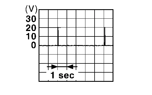
Intelligent Key battery is removed and brake pedal is depressed When a registered Intelligent Key backside is contacted to push-button ignition switch 0 V
Other than above
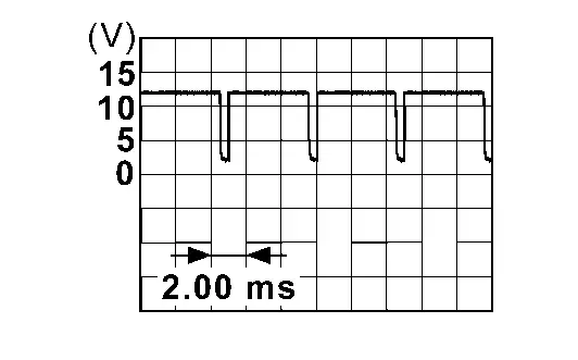
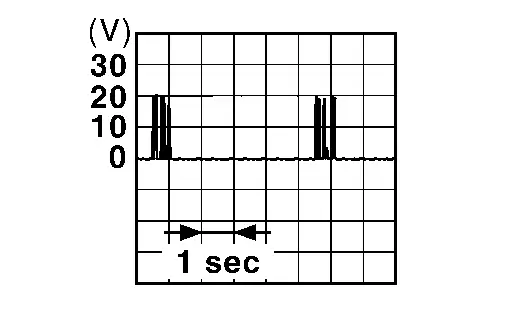
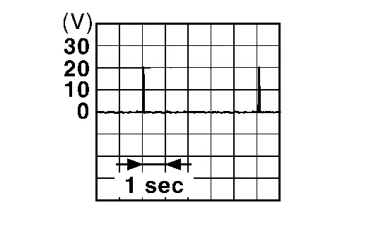
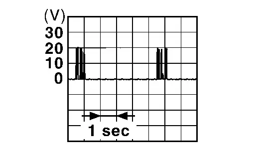
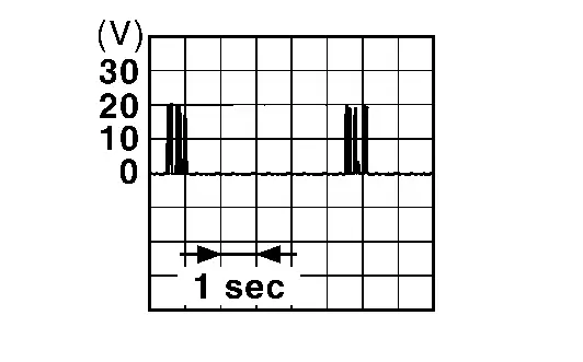
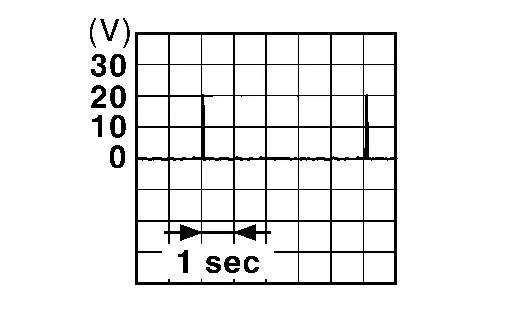
Inside key antenna Output Press push-button ignition switch When Intelligent Key is in the passenger compartment
When Intelligent Key is not in the passenger compartment

20

(LA/G)
Ground NATS antenna amp. Input/Output Intelligent Key battery is removed and brake pedal is depressed When a registered Intelligent Key backside is contacted to push-button ignition switch 0 V
Other than above
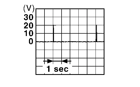
Inside key antenna Output Press push-button ignition switch When Intelligent Key is in the passenger compartment
When Intelligent Key is not in the passenger compartment

25*

(V)
Ground Door request switch (rear door LH) Input Door request switch (rear door LH) ON (pressed) 0 V
OFF (not pressed) 12 V

29

(B)
Ground Ground — — 0 V

31

(LA/P)
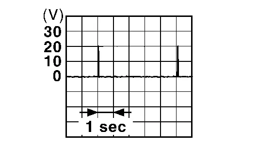
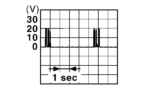
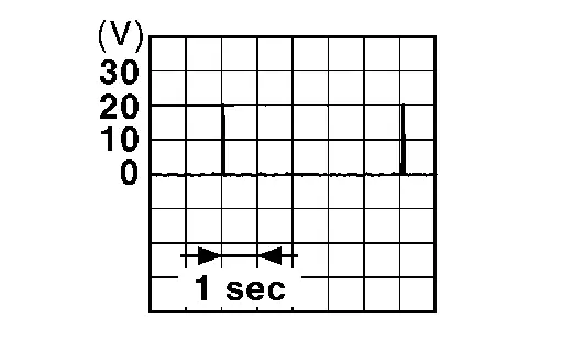
Ground Outside key antenna (rear door RH) Output When the door request switch (front door RH or rear door RH) is operated with ignition switch ON When Intelligent Key is in the antenna detection area
When Intelligent Key is not in the antenna detection area

32

(LA/L)
Ground Outside key antenna (rear door RH) Output When the door request switch (front door RH or rear door RH) is operated with ignition switch ON When Intelligent Key is in the antenna detection area
When Intelligent Key is not in the antenna detection area

33

(P)
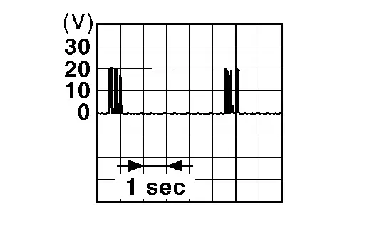
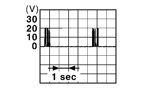
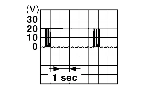
Ground Inside key antenna (console) Output Press push-button ignition switch When Intelligent Key is in the passenger compartment
When Intelligent Key is not in the passenger compartment

34

(GR)
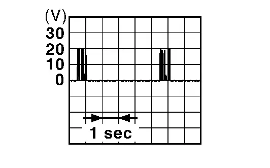
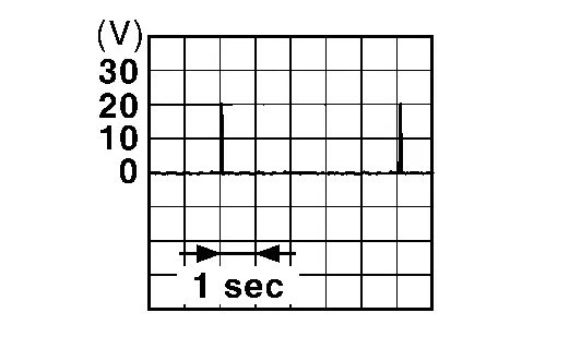
Ground Inside key antenna (console) Output Press push-button ignition switch When Intelligent Key is in the passenger compartment
When Intelligent Key is not in the passenger compartment

35

(LA/V)
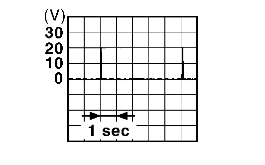
Ground Outside key antenna (rear door LH) Output When the door request switch (front door LH or rear door LH) is operated with ignition switch ON When Intelligent Key is in the antenna detection area
When Intelligent Key is not in the antenna detection area

36

(LA/W)
Ground Outside key antenna (rear door LH) Output When the door request switch (front door LH or rear door LH) is operated with ignition switch ON When Intelligent Key is in the antenna detection area
When Intelligent Key is not in the antenna detection area

37

(LA/V)
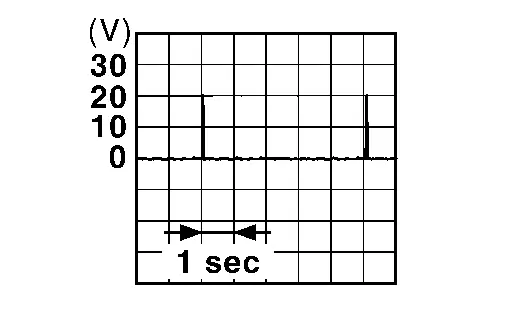
Ground Outside key antenna (rear bumper) Output When the back door request switch is operated with ignition switch ON When Intelligent Key is in the antenna detection area
When Intelligent Key is not in the antenna detection area

38

(LA/W)
Ground Outside key antenna (rear bumper) Output When the back door request switch is operated with ignition switch ON When Intelligent Key is in the antenna detection area
When Intelligent Key is not in the antenna detection area

39

(LA/L)
Ground Inside key antenna (luggage room) Output Press push-button ignition switch When Intelligent Key is in the passenger compartment
When Intelligent Key is not in the passenger compartment

40

(LA/LG)
Ground Inside key antenna (luggage room) Output Press push-button ignition switch When Intelligent Key is in the passenger compartment
When Intelligent Key is not in the passenger compartment

*: With rear door request switch models

DTC Inspection Priority Chart

If some DTCs are displayed at the same time, perform inspections one by one based on the following priority chart.

    • B2010-1C: Battery voltage

    • B2001-45: Intelligent Key unit

    • B2002-43: Intelligent Key unit

    • B2046-42: EEPROM

    • B2046-46: EEPROM

    • U2140-87: CAN ECM

    • U214E-87: CAN METER

    • U214F-86: CAN BCM

    • U2148-87: CAN VDC

    • U2152-86: CAN comm err (ADAS control unit)

    • U215B-86: CAN USM

    • B2033-4A: DONGLE NG

    • B2090-14: NATS antenna amp.

    • B2042-4A: Electric shift authentication fail

    • B2043-4A: Electric shift ID discord

    • B2044-4A: Electric shift ID registration fail

    • B2045-4A: Electric shift ID discord

    • B2047-87: Electric shift communication fail

    • B2080-01: Power switch

    • B2080-1C: Power switch

    • B2080-12: Power switch

    • B2080-14: Power switch

    • B2087-08: One touch sensor (FL)

    • B2087-11: One touch sensor (FL)

    • B2087-23: One touch sensor (FL)

    • B2087-24: One touch sensor (FL)

    • B2087-44: One touch sensor (FL)

    • B2088-08: One touch sensor (FR)

    • B2088-11: One touch sensor (FR)

    • B2088-23: One touch sensor (FR)

    • B2088-24: One touch sensor (FR)

    • B2088-44: One touch sensor (FR)

    • B2089-08: One touch sensor (RL)

    • B2089-11: One touch sensor (RL)

    • B2089-23: One touch sensor (RL)

    • B2089-24: One touch sensor (RL)

    • B2089-44: One touch sensor (RL)

    • B2091-08: One touch sensor (RR)

    • B2091-11: One touch sensor (RR)

    • B2091-23: One touch sensor (RR)

    • B2091-24: One touch sensor (RR)

    • B2091-44: One touch sensor (RR)

    • B2086-23: Request SW (BD/TR)

    • B2070-68: Key registration

    • B203C-14: Inside antenna

    • B203E-14: Outside antenna

    • B203F-14: Outside antenna

    • B2040-14: Outside antenna

DTC Index

  • CRNT: A malfunction is detected now.

  • PAST: A malfunction was detected in the past.

Self Diagnostic Result
CONSULT display Fail-safe Intelligent Key system malfunction displays Reference page

No DTC is detected.

Further testing may be required.
— — —
B2001-45: Intelligent Key unit — — DTC Description
B2002-43: Intelligent Key unit — — DTC Description
B2010-1C: Battery voltage — — DTC Description
B2033-4A: DONGLE NG — — DTC Description
B203C-14: Inside antenna — — DTC Description
B203E-14: Outside antenna — — DTC Description
B203F-14: Outside antenna — — DTC Description
B2040-14: Outside antenna — — DTC Description
B2042-4A: Electric shift authentication fail × — DTC Description
B2043-4A: Electric shift ID discord × — DTC Description
B2044-4A: Electric shift ID registration fail × — DTC Description
B2045-4A: Electric shift ID discord × — DTC Description
B2047-87: Electric shift communication fail × — DTC Description
B2046-42: EEPROM — — DTC Description
B2046-46: EEPROM — — DTC Description
B2070-68: Key registration — — DTC Description
B2080-01: Power switch — — DTC Description
B2080-1C: Power switch — —
B2080-12: Power switch — —
B2080-14: Power switch — —
B2086-23: Request SW (BD/TR) — — DTC Description
B2087-08: One touch sensor (FL) — — DTC Description
B2087-11: One touch sensor (FL) — —
B2087-23: One touch sensor (FL) — —
B2087-24: One touch sensor (FL) — —
B2087-44: One touch sensor (FL) — —
B2088-08: One touch sensor (FR) — — DTC Description
B2088-11: One touch sensor (FR) — —
B2088-23: One touch sensor (FR) — —
B2088-24: One touch sensor (FR) — —
B2088-44: One touch sensor (FR) — —
B2089-08: One touch sensor (RL) — — DTC Description
B2089-11: One touch sensor (RL) — —
B2089-23: One touch sensor (RL) — —
B2089-24: One touch sensor (RL) — —
B2089-44: One touch sensor (RL) — —
B2091-08: One touch sensor (RR) — — DTC Description
B2090-14: NATS antenna amp. — —
B2091-11: One touch sensor (RR) — —
B2091-23: One touch sensor (RR) — —
B2091-24: One touch sensor (RR) — —
B2091-44: One touch sensor (RR) — —
Network-DTC
CONSULT display Fail-safe Intelligent Key system malfunction displays Reference page
U2140-87: CAN ECM — — DTC Description
U2148-87: CAN VDC — — DTC Description
U214E-87: CAN METER — — DTC Description
U214F-86: CAN BCM — — DTC Description
U2152-86: CAN comm err (ADAS control unit) — — DTC Description
U215B-86: CAN USM — — DTC Description