Dtc/circuit Diagnosis (B242a-98 Closure Motor ... Automatic Back Door Serial Communication)
- B242a-98 Closure Motor
- B2436-11 Spindle Motor Lh
- B2436-12 Spindle Motor Lh
- B2436-98 Spindle Motor Lh
- B2f06-11 Trunk/back Door Opener Sw
- U0075-00 Communication Bus C Off
- U2140-87 Can Ecm
- U2141-87 Communication Lost with Atcu
- Automatic Back Door Close Switch
- Automatic Back Door Serial Communication
B242a-98 Closure Motor Nissan Pathfinder
DTC Description
DTC DETECTION LOGIC
| DTC No. | CONSULT screen items (Trouble diagnosis content) | DTC Detection Condition | |
|---|---|---|---|
| B242A-98 | Closure motor (Closure motor) |
Diagnosis condition | When back door closure function operate |
| Signal (terminal) | — | ||
| Threshold | When thermal protection operate of the closure motor | ||
| Diagnosis delay time | 20 seconds or more | ||
POSSIBLE CAUSE
Back door lock assembly (closure motor)
Continuous operation of the closure motor
Automatic back door control unit
FAIL-SAFE
Inhibit automatic back door system all function
DTC CONFIRMATION PROCEDURE
PERFORM DTC CONFIRMATION PROCEDURE
 CONSULT
Ignition switch ON and wait for 20 seconds or more.
Operate automatic back door.
Check “Self Diagnostic Result” mode of “AUTO BACK DOOR”.
Is DTC detected?
YES>>Refer to DTC Diagnosis Procedure.
NO>>To check malfunction symptom before repair: Refer to Intermittent Incident.
NO>>Confirmation after repair: Inspection End.
DTC Diagnosis Procedure
CHECK SELF DIAGNOSTIC RESULT
 CONSULT
Wait for 40 seconds or more.
Ignition switch ON.
Select “Self Diagnostic Result” mode of “AUTO BACK DOOR”.
What is the display history of DTC “B242A-98”?
“CRNT”>>GO TO 2.
“PAST”>>Inspection End.
CHECK CONNECTOR
Ignition switch OFF.
Check the automatic back door control unit harness connector for disconnection or looseness.
Is the inspection result normal?
YES>>GO TO 3.
NO>>Repair/replace harness or connector, securely lock the connector.
CHECK AUTOMATIC BACK DOOR CONTROL UNIT POWER SUPPLY AND GROUND CIRCUIT
Check the automatic back door control unit power supply and ground circuits. Refer to Diagnosis Procedure.
Is the inspection result normal?
YES>>GO TO 4.
NO>>Repair/replace harness, connector, fuse, or fusible link.
CHECK TERMINAL
Ignition switch OFF.
Disconnect automatic back door control unit harness connector and then check the automatic back door control unit pin terminals for damage or loose connection with harness connector.
Is the inspection result normal?
YES>>Replace automatic back door control unit. Refer to Removal and Installation.
NO>>Repair/replace harness, connector, or terminal.
B2436-11 Spindle Motor Lh Nissan Pathfinder SUV
DTC Description
DTC DETECTION LOGIC
| DTC No. | CONSULT screen items (Trouble diagnosis content) | DTC Detection Condition | |
|---|---|---|---|
| B2436-11 | Spindle motor LH (Spindle motor left hand) |
Diagnosis condition | All times |
| Signal (terminal) | Spindle motor LH signal | ||
| Threshold | Automatic back door control unit cannot detect the spindle motor LH signal | ||
| Diagnosis delay time | 1 second or less | ||
POSSIBLE CAUSE
Harness or connector (spindle motor LH circuit is ground open)
Automatic back door control unit
Spindle unit LH
FAIL-SAFE
Inhibit automatic back door system (only operate back door closure function)
DTC CONFIRMATION PROCEDURE
PERFORM DTC CONFIRMATION PROCEDURE
 CONSULT
Ignition switch ON.
Check “Self Diagnostic Result” mode of “AUTO BACK DOOR”.
Is DTC detected?
YES>>Refer to DTC Diagnosis Procedure.
NO>>To check malfunction symptom before repair: Refer to Intermittent Incident.
NO>>Confirmation after repair: Inspection End.
DTC Diagnosis Procedure
CHECK SPINDLE MOTOR INPUT SIGNAL
Check signal between spindle unit LH harness connector and ground using oscilloscope.
| (+) | (–) | Condition | Signal (Reference value) | ||
|---|---|---|---|---|---|
| Spindle unit LH | |||||
| Connector | Terminal | ||||
| B70 | 1 | Ground | Back door | Auto open operation | 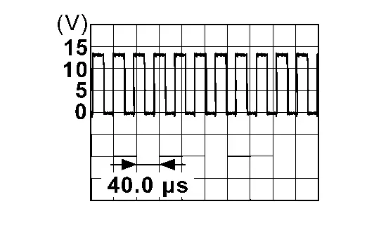 |
| Auto close operation | 0 – 1 V | ||||
| 7 | Auto close operation | 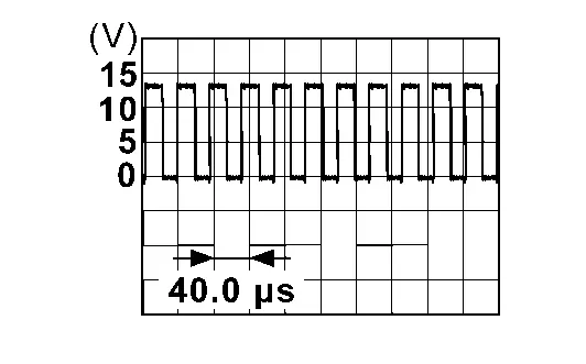 |
|||
| Auto open operation | 0 – 1 V | ||||
Is the inspection result normal?
YES>>GO TO 2.
NO>>GO TO 5.
CHECK CONNECTOR
Ignition switch OFF.
Check the automatic back door control unit harness connector for disconnection or looseness.
Check the spindle unit LH harness connector for disconnection or looseness.
Is the inspection result normal?
YES>>GO TO 3.
NO>>Repair/replace harness or connector, securely lock the connector, and GO TO 5.
CHECK AUTOMATIC BACK DOOR CONTROL UNIT POWER SUPPLY AND GROUND CIRCUIT
Check the automatic back door control unit power supply and ground circuits. Refer to Diagnosis Procedure.
Is the inspection result normal?
YES>>GO TO 4.
NO>>Repair/replace harness, connector, fuse, or fusible link, and GO TO 5.
CHECK TERMINAL
Ignition switch OFF.
Disconnect automatic back door control unit harness connector and then check the automatic back door control unit pin terminals for damage or loose connection with harness connector.
Disconnect spindle unit LH harness connector and check spindle unit LH pin terminal for damage or loose connection with harness connector.
Is the inspection result normal?
YES>>Replace automatic back door control unit. Refer to Removal and Installation.
NO>>Repair/replace harness, connector, or terminal.
CHECK SPINDLE MOTOR CIRCUIT
Ignition switch OFF.
Disconnect automatic back door control unit connector and spindle unit LH connector.
Check continuity between automatic back door control unit harness connector and spindle unit LH harness connector.
Automatic back door control unit Spindle unit LH Continuity Connector Terminal Connector Terminal B56 38 B70 1 Yes 39 7 Check continuity between automatic back door control unit harness connector and ground.
Automatic back door control unit (-) Continuity Connector Terminal B56 38 Ground No 39
Is the inspection result normal?
YES>>Replace spindle unit LH. Refer to Removal and Installation.
NO>>Repair or replace harness.
B2436-12 Spindle Motor Lh Nissan Pathfinder 5th Gen
DTC Description
DTC DETECTION LOGIC
| DTC No. | CONSULT screen items (Trouble diagnosis content) | DTC Detection Condition | |
|---|---|---|---|
| B2436-12 | Spindle motor LH (Spindle motor left hand) |
Diagnosis condition | All times |
| Signal (terminal) | Spindle motor LH signal | ||
| Threshold | When automatic back door control unit detect power short of spindle motor LH circuit | ||
| Diagnosis delay time | 1 second or less | ||
POSSIBLE CAUSE
Harness or connector (spindle motor LH circuit is power short)
Automatic back door control unit
Spindle unit LH
FAIL-SAFE
Inhibit automatic back door system (only operate back door closure function)
DTC CONFIRMATION PROCEDURE
PERFORM DTC CONFIRMATION PROCEDURE
 CONSULT
Ignition switch ON.
Check “Self Diagnostic Result” mode of “AUTO BACK DOOR”.
Is DTC detected?
YES>>Refer to DTC Diagnosis Procedure.
NO>>To check malfunction symptom before repair: Refer to Intermittent Incident.
NO>>Confirmation after repair: Inspection End.
DTC Diagnosis Procedure
CHECK SPINDLE MOTOR INPUT SIGNAL
Check signal between spindle unit LH harness connector and ground using oscilloscope.
| (+) | (–) | Condition | Signal (Reference value) | ||
|---|---|---|---|---|---|
| Spindle unit LH | |||||
| Connector | Terminal | ||||
| B70 | 1 | Ground | Back door | Auto open operation | 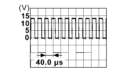 |
| Auto close operation | 0 – 1 V | ||||
| 7 | Auto close operation | 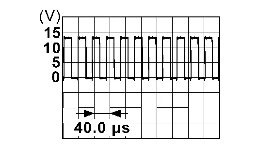 |
|||
| Auto open operation | 0 – 1 V | ||||
Is the inspection result normal?
YES>>Replace automatic back door control unit. Refer to Removal and Installation.
NO>>GO TO 2.
CHECK SPINDLE MOTOR CIRCUIT
Disconnect automatic back door control unit connector and spindle unit LH connector.
Check voltage between automatic back door control unit harness connector and ground.
Automatic back door control unit — Voltage
(Approx.)Connector Terminal B56 38 Ground 0 V 39
Is the inspection result normal?
YES>>Replace spindle unit LH. Refer to Removal and Installation.
NO>>Repair or replace harness.
B2436-98 Spindle Motor Lh Nissan Pathfinder 5th Gen
DTC Description
DTC DETECTION LOGIC
| DTC No. | CONSULT screen items (Trouble diagnosis content) | DTC Detection Condition | |
|---|---|---|---|
| B2436-98 | Spindle motor LH (Spindle motor left hand) |
Diagnosis condition | All times |
| Signal (terminal) | — | ||
| Threshold | When thermal protection operate of the spindle motor LH | ||
| Diagnosis delay time | 45 seconds or more | ||
POSSIBLE CAUSE
Automatic back door control unit
FAIL-SAFE
Inhibit automatic back door system (only operate back door closure function)
DTC CONFIRMATION PROCEDURE
PERFORM DTC CONFIRMATION PROCEDURE
 CONSULT
Ignition switch ON and wait for 45 seconds or more.
Check “Self Diagnostic Result” mode of “AUTO BACK DOOR”.
Is DTC detected?
YES>>Refer to DTC Diagnosis Procedure.
NO>>To check malfunction symptom before repair: Refer to Intermittent Incident.
NO>>Confirmation after repair: Inspection End.
DTC Diagnosis Procedure
CHECK SELF DIAGNOSTIC RESULT
 CONSULT
Wait for 75 seconds or more.
Ignition switch ON.
Select “Self Diagnostic Result” mode of “AUTO BACK DOOR”.
What is the display history of DTC “B2436-98”?
“CRNT”>>Replace automatic back door control unit. Refer to Removal and Installation.
“PAST”>>Inspection End.
B2f06-11 Trunk/back Door Opener Sw Nissan Pathfinder 2026
DTC Description
DTC DETECTION LOGIC
| DTC No. | CONSULT screen items (Trouble diagnosis content) | DTC Detection Condition | |
|---|---|---|---|
| B2F06-11 | Back door/trunk opener switch (Back door/trunk opener switch) |
Diagnosis condition | Ignition switch ON. |
| Signal (terminal) | Back door opener switch signal (BCM connector terminal: 98) | ||
| Threshold | When the BCM detects the open or shorted circuit of the back door opener switch | ||
| Diagnosis delay time | 1 second or less | ||
POSSIBLE CAUSE
Back door opener switch
Harness or connectors (back door opener switch circuit is open or shorted)
BCM
FAIL-SAFE
—
DTC CONFIRMATION PROCEDURE
CHECK SELF-DIAG RESULT
 CONSULT
Ignition switch ON.
Check “Self Diagnostic Result” mode of “BCM”.
Is DTC detected?
YES>>Refer to DTC Diagnosis Procedure.
NO>>To check malfunction symptom before repair: Refer to Intermittent Incident.
NO>>Confirmation after repair: Inspection End.
DTC Diagnosis Procedure
CHECK BACK DOOR OPEN INPUT SIGNAL
Ignition switch OFF.
Disconnect back door opener switch connector.
Check voltage between back door opener switch harness connector and ground.
(+) (–) Voltage
(Approx.)Back door opener switch Connector Terminal D559 1 Ground Battery voltage
Is the inspection result normal?
YES>>GO TO 3.
NO>>GO TO 2.
CHECK BACK DOOR OPENER SWITCH CIRCUIT
Disconnect BCM connector.
Check continuity between BCM harness connector and back door opener switch harness connector.
BCM Back door opener switch Continuity Connector Terminal Connector Terminal B59 98 D559 1 Yes Check continuity between BCM harness connector and ground.
BCM — Continuity Connector Terminal B59 98 Ground No
Is the inspection result normal?
YES>>Replace BCM. Refer to Removal and Installation.
NO>>Repair or replace harness.
CHECK BACK DOOR OPENER SWITCH GROUND CIRCUIT
Check continuity between back door opener switch harness connector and ground.
| Back door opener switch | — | Continuity | |
|---|---|---|---|
| Connector | Terminal | ||
| D559 | 2 | Ground | Yes |
Is the inspection result normal?
YES>>GO TO 4.
NO>>Repair or replace harness.
CHECK BACK DOOR OPENER SWITCH
Refer to Component Inspection.
Is the inspection result normal?
YES>>GO TO 5.
NO>>Replace back door opener switch. Refer to Removal and Installation.
CHECK INTERMITTENT INCIDENT
Refer to Intermittent Incident.
>>Inspection End.
U0075-00 Communication Bus C Off Nissan Pathfinder
DTC Description
DTC DETECTION LOGIC
| DTC No. | CONSULT screen items (Trouble diagnosis content) | DTC Detection Condition | |
|---|---|---|---|
| U0075-00 | Control module comm Bus C Off (Control module communication Bus C Off) |
Diagnosis condition | Ignition switch ON |
| Signal (terminal) | CAN communication signal | ||
| Threshold | Automatic back door control unit is unable to receive the CAN communication signal from the following control unit.
|
||
| Diagnosis delay time | 2 seconds or more | ||
POSSIBLE CAUSE
CAN communication system
FAIL-SAFE
Inhibit automatic back door system all function
DTC CONFIRMATION PROCEDURE
PERFORM DTC CONFIRMATION PROCEDURE
 CONSULT
Ignition switch OFF.
Ignition switch ON and wait for 2 seconds or more.
Check “Self Diagnostic Result” mode of “AUTO BACK DOOR”.
Is DTC detected?
YES>>Refer to DTC Diagnosis Procedure.
NO>>To check malfunction symptom before repair: Refer to Intermittent Incident.
NO>>Confirmation after repair: Inspection End.
DTC Diagnosis Procedure
CHECK CAN COMMUNICATION
Check CAN communication. Refer toTrouble Diagnosis Flow Chart
Is DTC “U0075-00” displayed?
YES>>Repair or replace the malfunctioning part.
NO>>Check intermittent incident. Refer to Intermittent Incident.
U2140-87 Can Ecm Nissan Pathfinder Fifth generation
DTC Description
DESCRIPTION
CAN (Controller Area Network) is a serial communication line for real time applications. It is an on-Nissan Pathfinder vehicle multiplex communication line with high data communication speed and excellent error detection ability. Modern Nissan Pathfinder vehicles are equipped with many electronic control units, and each control unit shares information and links with other control units during operation (not independent). In CAN communication, control units are connected with 2 communication lines (CAN-High line, CAN-Low line) allowing a high rate of information transmission with less wiring. Each control unit transmits/receives data but selectively reads required data only. CAN Communication Signal Chart. Refer to CAN Communication Signal Chart.
DTC DETECTION LOGIC
| DTC No. | CONSULT screen items (Trouble diagnosis content) | DTC Detection Condition | |
|---|---|---|---|
| U2140-87 | CAN ECM [CAN communication error (ECM)] |
Diagnosis condition | Ignition switch ON |
| Signal (terminal) | CAN communication signal | ||
| Threshold | Transmission error or reception error | ||
| Diagnosis delay time | 2 seconds or more | ||
POSSIBLE CAUSE
CAN communication system
FAIL-SAFE
—
DTC CONFIRMATION PROCEDURE
CHECK SELF-DIAG RESULT
 CONSULT
Ignition switch ON and wait for 2 seconds or more.
Check “Self Diagnostic Result” mode of “HANDS FREE MODULE”.
Is DTC detected?
YES>>Refer to DTC Diagnosis Procedure .
NO>>To check malfunction symptom before repair: Refer to Intermittent Incident.
NO>>Confirmation after repair: Inspection End.
Diagnosis Procedure
CHECK CAN COMMUNICATION
Check CAN communication. Refer to Trouble Diagnosis Flow Chart.
Is DTC “U2140-87” displayed?
YES>>Repair or replace the malfunctioning part.
NO>>Check intermittent incident. Refer to Intermittent Incident.
U2141-87 Communication Lost with Atcu Nissan Pathfinder 5th Gen
DTC Description
DESCRIPTION
CAN (Controller Area Network) is a serial communication line for real time applications. It is an on-Nissan Pathfinder vehicle multiplex communication line with high data communication speed and excellent error detection ability. Modern Nissan Pathfinder vehicles are equipped with many electronic control units, and each control unit shares information and links with other control units during operation (not independent). In CAN communication, control units are connected with 2 communication lines (CAN-High line, CAN-Low line) allowing a high rate of information transmission with less wiring. Each control unit transmits/receives data but selectively reads required data only. CAN Communication Signal Chart. Refer to CAN Communication Signal Chart.
DTC DETECTION LOGIC
| DTC No. | CONSULT screen items (Trouble diagnosis content) | DTC Detection Condition | |
|---|---|---|---|
| U2141-87 | Communication lost with ATCU [CAN communication error (TCM)] |
Diagnosis condition | Ignition switch ON |
| Signal (terminal) | CAN communication signal | ||
| Threshold | Automatic back door control unit is unable to receive the CAN communications signal from TCM | ||
| Diagnosis delay time | 2 seconds or less | ||
POSSIBLE CAUSE
CAN communication system
FAIL-SAFE
Inhibit automatic back door system all function
DTC CONFIRMATION PROCEDURE
PERFORM DTC CONFIRMATION PROCEDURE
 CONSULT
Ignition switch OFF.
Ignition switch ON and wait for 2 seconds or more.
Check “Self Diagnostic Result” mode of “AUTO BACK DOOR”.
Is DTC detected?
YES>>Refer to DTC Diagnosis Procedure.
NO>>To check malfunction symptom before repair: Refer to Intermittent Incident.
NO>>Confirmation after repair: Inspection End.
DTC Diagnosis Procedure
CHECK CAN COMMUNICATION
Check CAN communication. Refer to Trouble Diagnosis Flow Chart.
Is DTC “U2141-87” displayed?
YES>>GO TO 2.
NO>>Check intermittent incident. Refer to Intermittent Incident.
CHECK CONNECTOR
Ignition switch OFF.
Check the automatic back door control unit harness connector for disconnection or looseness.
Is the inspection result normal?
YES>>GO TO 3.
NO>>Repair/replace harness or connector, securely lock the connector.
CHECK AUTOMATIC BACK DOOR CONTROL UNIT POWER SUPPLY AND GROUND CIRCUIT
Check the automatic back door control unit power supply and ground circuits. Refer to Diagnosis Procedure.
Is the inspection result normal?
YES>>GO TO 4.
NO>>Repair/replace harness, connector, fuse, or fusible link.
CHECK TERMINAL
Ignition switch OFF.
Disconnect automatic back door control unit harness connector and then check the automatic back door control unit pin terminals for damage or loose connection with harness connector.
Is the inspection result normal?
YES>>Replace automatic back door control unit. Refer to Removal and Installation.
NO>>Repair/replace harness, connector, or terminal.
Automatic Back Door Close Switch Nissan Pathfinder Fifth generation
ComponentFunctionCheck
CHECK FUNCTION
 CONSULT
Ignition switch ON.
Select “AUTO BACK DOOR".
Select “Automatic back door close SW” in “DATA MONITOR” mode.
Check that the function operates normally according to the following conditions.
| Monitor item | Condition | Status | |
|---|---|---|---|
| Automatic back door close SW | Automatic back door close switch | Pressed | On |
| Released | Off | ||
Is the inspection result normal?
YES>>Automatic back door close switch is OK.
NO>>Refer to Diagnosis Procedure.
Diagnosis Procedure
CHECK AUTOMATIC BACK DOOR CLOSE SWITCH INPUT SIGNAL
Ignition switch OFF.
Disconnect automatic back door lock and close switch assembly connector.
Check voltage between automatic back door lock and close switch assembly harness connector and ground.
(+) (–) Voltage
(Approx.)Automatic back door lock and close switch assembly Connector Terminal D551 11 Ground Battery voltage
Is the inspection result normal?
YES>>GO TO 3.
NO>>GO TO 2.
CHECK AUTOMATIC BACK DOOR CLOSE SWITCH CIRCUIT
Disconnect automatic back door control unit connector.
Check continuity between automatic back door control unit harness connector and automatic back door lock and close switch assembly harness connector.
Automatic back door control unit Automatic back door lock and close switch assembly Continuity Connector Terminal Connector Terminal B55 3 D551 11 Yes Check continuity between automatic back door control unit harness connector and ground.
Automatic back door control unit (-) Continuity Connector Terminal B55 3 Ground No
Is the inspection result normal?
YES>>Replace automatic back door control unit. Refer to Removal and Installation.
NO>>Repair or replace harness.
CHECK AUTOMATIC BACK DOOR CLOSE SWITCH GROUND CIRCUIT
Check continuity between automatic back door lock and close switch assembly harness connector and ground.
| Automatic back door lock and close switch assembly | (-) | Continuity | |
|---|---|---|---|
| Connector | Terminal | ||
| D551 | 7 | Ground | Yes |
Is the inspection result normal?
YES>>GO TO 4.
NO>>Repair or replace harness.
CHECK AUTOMATIC BACK DOOR CLOSE SWITCH
Refer to Component Inspection.
Is the inspection result normal?
YES>>GO TO 5.
NO>>Replace automatic back door lock and close switch assembly. Refer to Removal and Installation.
CHECK INTERMITTENT INCIDENT
Refer to Intermittent Incident.
>>Inspection End.
Component Inspection
CHECK AUTOMATIC BACK DOOR CLOSE SWITCH
Ignition switch OFF.
Disconnect automatic back door lock and close switch assembly connector.
Check continuity between automatic back door lock and close switch assembly terminals.
| Automatic back door lock and close switch assembly | Condition | Continuity | ||
|---|---|---|---|---|
| Terminal | ||||
| 11 | 7 | Automatic back door close switch | Pressed | Yes |
| Released | No | |||
Is the inspection result normal?
YES>>Inspection End.
NO>>Replace automatic back door lock and close switch assembly. Refer to Removal and Installation.
Automatic Back Door Serial Communication Nissan Pathfinder 2022
Diagnosis Procedure
CHECK AUTOMATIC BACK DOOR SERIAL COMMUNICATION SIGNAL
Ignition switch ON.
Check signal between BCM harness connector and ground using oscilloscope.
(+) (–) Signal
(Reference value)BCM Connector Terminal B59 83 Ground 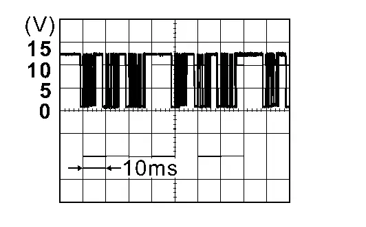
Is the inspection result normal?
YES>>Inspection End.
NO>>GO TO 2.
CHECK AUTOMATIC BACK DOOR SERIAL COMMUNICATION CIRCUIT
Ignition switch OFF.
Disconnect hands free sensor control unit connector and BCM connector.
Check continuity between hands free sensor control unit harness connector and BCM harness connector.
Hands free sensor control unit BCM Continuity Connector Terminal Connector Terminal B459 1 B59 83 Yes Check continuity between hands free sensor control unit harness connector and ground.
Hands free sensor control unit (-) Continuity Connector Terminal B459 1 Ground No
Is the inspection result normal?
YES>>Replace BCM. Refer to Removal and Installation.
NO>>Repair or replace harness.