Ecu Diagnosis Information
In this manual: Ecu Diagnosis Information
~11min read
- Driver Seat Control Unit
- Steering Column Control Module
Driver Seat Control Unit Nissan Ariya 1st generation
Reference Value
VALUES ON THE DIAGNOSIS TOOL
| Monitor Item | Condition | Value/Status | |
|---|---|---|---|
| Memory switch 1 | Memory switch-1 | Press | On |
| Release | Off | ||
| Memory switch 2 | Memory switch-2 | Press | On |
| Release | Off | ||
| Set switch | Set switch | Press | On |
| Release | Off | ||
| Console slide switch (Forward) | Console slide switch | Operate (forward) | On |
| Release | Off | ||
| Console slide switch (Backward) | Console slide switch | Operate (backward) | On |
| Release | Off | ||
| Reclining switch (Forward) | Reclining switch | Operate (forward) | On |
| Release | Off | ||
| Reclining switch (Backward) | Reclining switch | Operate (backward) | On |
| Release | Off | ||
| Thigh support switch (Up) | Thigh support switch | Operate (upward) | On |
| Release | Off | ||
| Thigh support switch (Down) | Thigh support switch | Operate (downward) | On |
| Release | Off | ||
| Sliding switch (Forward) | Sliding switch | Operate (forward) | On |
| Release | Off | ||
| Sliding switch (Backward) | Sliding switch | Operate (backward) | On |
| Release | Off | ||
| Lifting switch (Up) | Lifting switch | Operate (upward) | On |
| Release | Off | ||
| Lifting switch (Down) | Lifting switch | Operate (downward) | On |
| Release | Off | ||
| Lifting motor position | Seat lifting | Operate (upward) | Change (increase) |
| Operate (downward) | Change (decrease) | ||
| Other than the above | No change | ||
| Reclining motor position | Seat reclining | Operate (forward) | Change (increase) |
| Operate (backward) | Change (decrease) | ||
| Other than the above | No change | ||
| Thigh support motor position | Thigh support | Operate (upward) | Change (increase) |
| Operate (downward) | Change (decrease) | ||
| Other than the above | No change | ||
| Console slide motor position | Console slide | Operate (forward) | Change (increase) |
| Operate (backward) | Change (decrease) | ||
| Other than the above | No change | ||
| Sliding motor position | Seat sliding | Operate (forward) | Change (increase) |
| Operate (backward) | Change (decrease) | ||
| Other than the above | No change | ||
TERMINAL LAYOUT
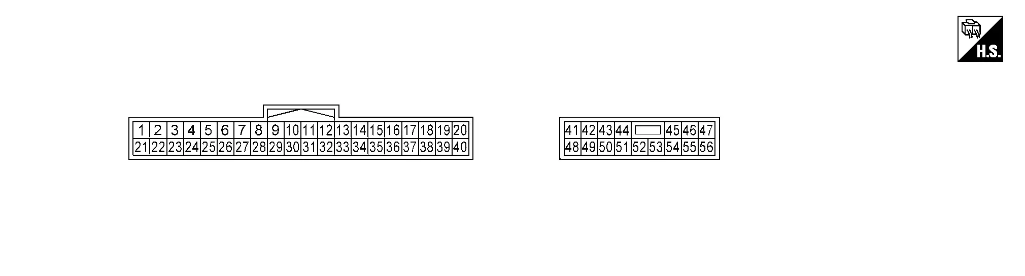
PHYSICAL VALUES
Terminal No. (Wire color) | Description | Condition | Value (Approx.) | |||
|---|---|---|---|---|---|---|
| + | - | Signal name | Input/output | |||
7 (L) |
Ground | Thigh support switch | Input | Thigh support switch | Operate (upward) | 1.524 – 3.268 V |
| Operate (downward) | 0.647 – 1.522 V | |||||
| Release | 3.269 – 4.799 V* | |||||
9 (R/LG) |
Ground | Memory switch-1 | Input | Memory switch-1 | Press | 0 – 2 V |
| Release | 12 V* | |||||
10 (LG) |
Ground | Memory switch-2 | Input | Memory switch-2 | Press | 0 – 2 V |
| Release | 12 V* | |||||
11 (Y) |
Ground | Reclining switch | Input | Reclining switch | Operate (forward) | 1.524 – 3.268 V |
| Operate (backward) | 0.647 – 1.522 V | |||||
| Release | 3.269 – 4.799 V* | |||||
12 (SB) |
Ground | Set switch | Input | Set switch | Press | 0 – 2 V |
| Release | 12 V* | |||||
14 (LG) |
Ground | Console slide sensor | Input | Console slide | Operate | 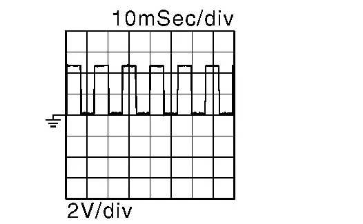 |
| Other than the above | 0 or 5 V (Depends on the stop position of the motor) | |||||
15 (W) |
Ground | Thigh support sensor | Input | Thigh support | Operate | |
| Other than the above | 0 or 5 V (Depends on the stop position of the motor) | |||||
16 (L) |
Ground | Lifting sensor | Input | Seat lifting | Operate | |
| Other than the above | 0 or 5 V (Depends on the stop position of the motor) | |||||
18 (BR) |
Ground | Memory indicator-2 | Output | Memory indicator-2 | Illuminate | 0 – 1.5 V |
| Other than the above | Battery voltage | |||||
19 (R) |
— | CAN-L | Input/Output | — | — | |
20 (L) |
— | CAN-H | Input/Output | — | — | |
25 (P) |
Ground | Console slide switch | Input | Console slide switch | Operate (forward) | 1.524 – 3.268 V |
| Operate (backward) | 0.647 – 1.522 V | |||||
| Release | 3.963 – 4.799 V | |||||
31 (P) |
Ground | Sliding / lifting switch | Input | Sliding switch | Operate (forward) | 3.065 – 3.962 V |
| Operate (backward) | 2.638 – 3.064 V | |||||
| Lifting switch | Operate (upward) | 0.789 – 1.755 V | ||||
| Operate (downward) | 0.352 – 0.788 V | |||||
| Sliding / lifting switch release | 3.963 – 4.799 V* | |||||
32 (B) |
Ground | Power seat / console slide switch ground | — | Always | 0 V | |
33 (B) |
Ground | Sensor ground | — | Always | 0 V | |
34 (SB) |
Ground | Sensor power supply | Output | Always | 13.5 V | |
35 (LG) |
Ground | Sliding sensor | Input | Seat sliding | Operate | |
| Other than the above | 0 or 5 V (Depends on the stop position of the motor) | |||||
36 (P) |
Ground | Reclining sensor | Input | Seat reclining | Operate | |
| Other than the above | 0 or 5 V (Depends on the stop position of the motor) | |||||
38 (Y) |
Ground | Memory indicator-1 | Output | Memory indicator-1 | Illuminate | 0 – 1.5 V |
| Other than the above | Battery voltage | |||||
40 (G) |
Ground | LIN | Input/Output | When the power consumption control of driver seat control unit is in wake-up state. | 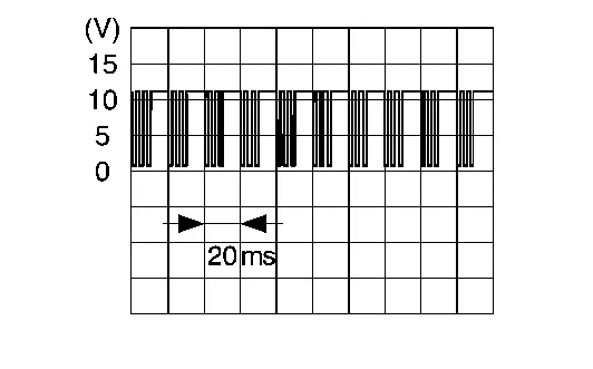 |
|
| When the power consumption control of driver seat control unit is in sleep state. | 12. 5 V | |||||
41 (V) |
Ground | Console slide motor (backward) | Output | Console slide | Operate (backward) | 13.5 V |
| Other than the above | 0 – 1 V | |||||
42 (P) |
Ground | Console slide motor (forward) | Output | Console slide | Operate (forward) | 13.5 V |
| Other than the above | 0 – 1 V | |||||
43 (P) |
Ground | Sliding motor (forward) | Output | Seat sliding | Operate (forward) | 13.5 V |
| Other than the above | 0 – 1 V | |||||
44 (V) |
Ground | Sliding motor (backward) | Output | Seat sliding | Operate (backward) | 13.5 V |
| Other than the above | 0 – 1 V | |||||
45 (L) |
Ground | Lifting motor (upward) | Output | Seat lifting | Operate (upward) | 13.5 V |
| Other than the above | 0 – 1 V | |||||
46 (G) |
Ground | Lifting motor (downward) | Output | Seat lifting | Operate (downward) | 13.5 V |
| Other than the above | 0 – 1 V | |||||
47 (Y) |
Ground | Reclining motor (forward) | Output | Seat reclining | Operate (forward) | 13.5 V |
| Other than the above | 0 – 1 V | |||||
48 (R) |
Ground | Battery power supply | — | Always | Battery voltage | |
51 (B) |
Ground | Ground | — | Always | 0 V | |
52 (O) |
Ground | Thigh support motor (downward) | Output | Thigh support | Operate (downward) | 13.5 V |
| Other than the above | 0 – 1 V | |||||
53 (GY) |
Ground | Thigh support motor (upward) | Output | Thigh support | Operate (upward) | 13.5 V |
| Other than the above | 0 – 1 V | |||||
56 (W) |
Ground | Reclining motor (backward) | Output | Seat reclining | Operate (backward) | 13.5 V |
| Other than the above | 0 – 1 V | |||||
*: When the power consumption control of driver seat control unit is in wake-up state.
Fail-safe
Refer to Fail-safe.
DTC Index
×: Applicable
| DTC No. | CONSULT display | Fail-safe | Reference |
|---|---|---|---|
| B2900-01 | Sliding / lifting switch | × | DTC Description |
| B2920-09 | Driver seat control unit | × | DTC Description |
| B2920-47 | Driver seat control unit | × | DTC Description |
| B2920-48 | Driver seat control unit | × | DTC Description |
| B2920-49 | Driver seat control unit | × | DTC Description |
| B2921-A2 | Driver seat control unit | × | DTC Description |
| B2921-A3 | Driver seat control unit | × | DTC Description |
| B2924-49 | Seat pneumatic control unit | — | DTC Description |
| B2924-A2 | Seat pneumatic control unit | — | DTC Description |
| B2924-A3 | Seat pneumatic control unit | — | DTC Description |
| B2925-07 | Seat pneumatic control unit | — | DTC Description |
| B2926-49 | Seat pneumatic control unit | — | DTC Description |
| U1CE0-87 | Seat pneumatic control unit | — | DTC Description |
| U2118-87 | CAN communication error (Intelligent Key) | × | DTC Description |
| U2140-87 | CAN communication error (ECM) | × | DTC Description |
| U2141-87 | CAN communication error (TCM) | × | DTC Description |
| U2148-87 | CAN communication error (brake control unit) | × | DTC Description |
| U214E-87 | CAN communication error (combination meter) | × | DTC Description |
| U214F-87 | CAN communication error (BCM) | × | DTC Description |
| U2150-87 | CAN communication error (AIRBAG) | × | DTC Description |
| U2154-87 | CAN communication error (MIU) | × | DTC Description |
| U2156-87 | CAN communication error (steering angel sensor) | × | DTC Description |
| U215B-87 | CAN communication error (IPDM E/R) | × | DTC Description |
| U2194-87 | CAN communication error (passenger seat control unit) | × | DTC Description |
| U2195-87 | CAN communication error (steering column control module) | × | DTC Description |
Steering Column Control Module Nissan Ariya
Reference Value
VALUES ON THE DIAGNOSIS TOOL
| Monitor Item | Condition | Value/Status | |
|---|---|---|---|
| Tilt switch (Up) | Tilt switch | Operate (upward) | On |
| Release | Off | ||
| Tilt switch (Down) | Tilt switch | Operate (downward) | On |
| Release | Off | ||
| Telescopic switch (Forward) | Telescopic switch | Operate (forward) | On |
| Release | Off | ||
| Telescopic switch (Backward) | Telescopic switch | Operate (backward) | On |
| Release | Off | ||
| Tilt & telescopic switch | Tilt & telescopic switch | Malfunction (Over current) | Invalid |
| Malfunction (Short to ground) | Short to ground | ||
| Malfunction (Open) | Open | ||
| Normal | OPERATIONAL | ||
| Tilt (Up) range | Tilt motor | Within the upward movable range | Within range |
| Out of upward movable range | Out of range | ||
| Tilt (Down) range | Tilt motor | Within the downward movable range | Within range |
| Out of downward movable range | Out of range | ||
| Telescopic (Forward) range | Telescopic motor | Within the forward movable range | Within range |
| Out of forward movable range | Out of range | ||
| Telescopic (Backward) range | Telescopic motor | Within the backward movable range | Within range |
| Out of backward movable range | Out of range | ||
| Tilt motor position | Steering tilt | Operate (upward) | Change (increase) |
| Operate (downward) | Change (decrease) | ||
| Other than the above | No change | ||
| Telescopic motor position | Steering telescopic | Operate (forward) | Change (increase) |
| Operate (backward) | Change (decrease) | ||
| Other than the above | No change | ||
TERMINAL LAYOUT

PHYSICAL VALUES
Terminal No. (Wire color) | Description | Condition | Value (Approx.) | |||
|---|---|---|---|---|---|---|
| + | - | Signal name | Input/output | |||
1 (SB) |
Ground | Telescopic sensor | Input | Steering telescopic | Operate | |
| Other than the above | 0 or 5 V (Depends on the stop position of the motor) | |||||
2 (LG) |
Ground | Telescopic sensor power supply | Output | Always | 13.5 V | |
3 (G) |
Ground | Telescopic sensor ground | — | Always | 0 V | |
4 (LG) |
Ground | Tilt & telescopic switch | Input | Telescopic switch | Operate (forward) | 2.0 V |
| Operate (backward) | 1.0 V | |||||
| Tilt switch | Operate (upward) | 1.5 V | ||||
| Operate (downward) | 0.5 V | |||||
| Tilt & telesopic switch release | 4.0 V* | |||||
6 (L) |
— | CAN-H | Input/Output | — | — | |
7 (L) |
Ground | Tilt sensor | Input | Steering tilt | Operate | |
| Other than the above | 0 or 5 V (Depends on the stop position of the motor) | |||||
8 (P) |
Ground | Tilt sensor power supply | Output | Always | 13.5 V | |
9 (Y) |
Ground | Tilt sensor ground | — | Always | 0 V | |
10 (BR) |
Ground | Tilt & telescopic switch ground | — | Always | 0 V | |
12 (R) |
— | CAN-L | Input/Output | — | — | |
13 (V) |
Ground | Battery power supply | — | Always | Battery voltage | |
14 (B) |
Ground | Ground | — | Always | 0 V | |
15 (R) |
Ground | Tilt motor (upward) | Output | Steering tilt | Operate (upward) | 13.5 V |
| Other than the above | 0 – 1 V | |||||
16 (SB) |
Ground | Tilt motor (downward) | Output | Steering tilt | Operate (downward) | 13.5 V |
| Other than the above | 0 – 1 V | |||||
17 (V) |
Ground | Telescopic motor (backward) | Output | Steering telescopic | Operate (backward) | 13.5 V |
| Other than the above | 0 – 1 V | |||||
18 (BR) |
Ground | Telescopic motor (forward) | Output | Steering telescopic | Operate (forward) | 13.5 V |
| Other than the above | 0 – 1 V | |||||
*: When the power consumption control of steering column control module is in wake-up state.
Fail-safe
Refer to Fail-safe.
DTC Index
×: Applicable
| DTC No. | CONSULT display | Fail-safe | Reference |
|---|---|---|---|
| B2980-44 | Steering column control module | × | DTC Description |
| B2980-45 | Steering column control module | × | DTC Description |
| B2980-46 | Steering column control module | × | DTC Description |
| B2980-47 | Steering column control module | × | DTC Description |
| B2980-48 | Steering column control module | × | DTC Description |
| B2980-49 | Steering column control module | × | DTC Description |
| B2981-A2 | ECU voltage | × | DTC Description |
| B2981-A3 | ECU voltage | × | DTC Description |
| B2982-11 | Tilt & telescopic switch status | × | DTC Description |
| B2982-13 | Tilt & telescopic switch status | × | DTC Description |
| B298A-77 | Tilt motor | × | DTC Description |
| B298A-93 | Tilt motor | × | DTC Description |
| B298D-77 | Telescopic motor | × | DTC Description |
| B298D-93 | Telescopic motor | × | DTC Description |
| U1CF0-86 | Nissan Ariya Vehicle speed signal | × | DTC Description |
| U2141-87 | CAN communication error (TCM) | × | DTC Description |
| U2148-87 | CAN communication error (brake control unit) | × | DTC Description |
| U214E-87 | CAN communication error (combination meter) | × | DTC Description |
| U214F-87 | CAN communication error (BCM) | × | DTC Description |
| U2150-87 | CAN communication error (AIRBAG) | × | DTC Description |
| U2154-87 | CAN communication error (MIU) | × | DTC Description |
| U215B-87 | CAN communication error (IPDM E/R) | × | DTC Description |
| U2193-87 | CAN communication error (driver seat control unit) | × | DTC Description |
Was this page helpful?