System

In this manual: System
How to Use This Manual — 1Precautions — 1Preparation — 1Vehicle Information — 1Basic Inspection — 1Preparation. Commercial Service Tools Or/and Repair Part — 1Description — 1Component Parts — 1System — 1Diagnosis System (vcm) — 1Ecu Diagnosis Information. Vcm — 1Ev Control System — 1Ev/hev (vcm) — 1Component Parts /circuit Diagnosis — 1Ev Control System — 1Periodic Maintenance. Ev System Warning Lamp — 1Removal and Installation. Vcm — 1Traction Motor System :: Front Traction Motor — 1Preparation — 1Description — 4Basic Inspection — 2Dtc Diagnosis — 2Component Parts /circuit Diagnosis — 1Traction Motor System :: Rear Traction Motor — 1Description — 4Basic Inspection — 2Dtc Diagnosis — 2Component Parts /circuit Diagnosis — 1Removal and Installation — 1Ev Battery System :: 66kwh Li-Ion Battery — 1Description — 4Basic Inspection — 2Dtc Diagnosis — 2Component Parts /circuit Diagnosis — 1Removal and Installation — 1Disassembly and Assembly — 2Service Data — 1Ev Battery System :: 91kwh Li-Ion Battery — 1Description — 4Basic Inspection — 2Dtc Diagnosis — 2Component Parts /circuit Diagnosis — 1Removal and Installation — 1Disassembly and Assembly — 1Service Data — 2Preparation. Vehicle Charging System — 1Vehicle Charging System :: Description — 1Component Parts — 2System — 1Diagnosis System (on-Board Charger) — 1Diagnosis System (dc/dc Converter) — 1Ecu Diagnosis Information — 1Vehicle Charging System — 1Charger/pd Module (on-Board Charger) — 1Cplc (cplc) — 1Dcdc (dc/dc Converter) — 1Component Parts/circuit Diagnosis — 1Symptom Diagnosis — 1Evse Inspection — 1Periodic Maintenance — 1Removal and Installation — 1Disassembly and Assembly — 1Preparation. High Voltage Cooling System — 1Description — 1Symptom Diagnosis. Overheating Cause Analysis — 1Periodic Maintenance — 1Coolant — 1Removal and Installation — 1Radiator — 1Service Data — 1Removal and Installation. Accelerator Control System — 1Reduction Gear: Re1f62a — 1Removal and Installation — 1Transaxle & Transmission :: Electric Shift — 1Description — 3Basic Inspection — 2Dtc Diagnosis — 2Component Parts /circuit Diagnosis — 1Removal and Installation — 1Rear Final Drive: Rn1r62a — 1Removal and Installation — 1Preparation. Front Axle System — 1Symptom Diagnosis. Noise, Vibration and Harshness (nvh) Troubleshooting — 1Periodic Maintenance — 1Removal and Installation — 1Service Data. Front Drive Shaft — 12wd — 14wd — 1Periodic Maintenance — 1Removal and Installation — 1Preparation. Front Suspension System — 1Symptom Diagnosis. Noise, Vibration and Harshness (nvh) Troubleshooting — 1Periodic Maintenance — 1Removal and Installation — 1Service Data — 1Symptom Diagnosis. Noise, Vibration and Harshness (nvh) Troubleshooting — 1Periodic Maintenance — 1Removal and Installation — 1Service Data — 1Preparation. Road Wheels & Tires System — 1Description — 1System — 1Ecu Diagnosis Information. Bcm (body Control Module) — 1Tpms — 1Dtc/circuit Diagnosis — 1Symptom Diagnosis — 1Periodic Maintenance. Road Wheels & Tires — 1Removal and Installation — 1Service Data — 1Preparation. Brake System — 1System Description — 1Component Parts — 1Ecu Diagnosis Information. Electrically-Driven Intelligent Brake Unit — 1Basic Inspection — 1Dtc/circuit Diagnosis — 1Symptom Diagnosis — 1Periodic Maintenance — 1Removal and Installation — 1Service Data — 1Preparation. Parking Brake System — 1System Description — 1Component Parts — 1System — 1Ecu Diagnosis Information. Abs Actuator and Electric Unit (control Unit) — 1Basic Inspection. Diagnosis and Repair Work Flow — 1Component Parts /circuit Diagnosis — 1Symptom Diagnosis — 1Removal and Installation — 1Brake Control System :: With Vdc — 1System Description — 3Basic Inspection — 2Dtc/circuit Diagnosis — 1Symptom Diagnosis — 2Removal and Installation — 1Brake Control System :: Automatic Brake Hold — 1System Description — 3Component Parts /circuit Diagnosis — 1Removal and Installation — 1Brake Control System :: E-Step — 1System Description — 3Removal and Installation — 1System Description — 1Ecu Diagnosis Information — 1Basic Inspection — 1Symptom Diagnosis — 1Rear Automatic Braking — 1System Description — 1Basic Inspection — 1Preparation. Steering System — 1System Description — 1Component Parts — 1Basic Inspection — 1Dtc/circuit Diagnosis — 1Symptom Diagnosis — 1Periodic Maintenance. Steering Wheel — 1Removal and Installation — 1Service Data — 1System Description — 1Component Parts — 1Steering Control System — 1Ecu Diagnosis Information. Power Steering Control Module — 1Dtc/circuit Diagnosis — 1Component Parts /circuit Diagnosis — 1Symptom Diagnosis — 1Removal and Installation. Power Steering Control Module — 1System Description — 1Removal and Installation — 1System Description — 1System — 1Basic Inspection. Diagnosis and Repair Work Flow — 1Dtc/circuit Diagnosis — 1Symptom Diagnosis — 1Component Parts — 1Basic Inspection — 1Removal and Installation — 1System Description — 1System — 1Ecu Diagnosis Information. Air Bag Diagnosis Sensor Unit — 1Basic Inspection — 1Dtc/circuit Diagnosis — 1Symptom Diagnosis — 1System Description. Description. Ventilation System — 1Removal and Installation — 1Preparation. Preparation — 1System Description — 1Basic Inspection — 1Symptom Diagnosis — 1Removal and Installation — 1Electric Compressor — 1Cooler Pipe and Hose — 1A/c Unit Assembly Cover — 1A/c Unit Assembly — 1Heater & Air Conditioning Control System :: Automatic Air Conditioning — 1System Description — 1Ecu Diagnosis Information — 1Basic Inspection — 2Dtc Diagnosis — 1Symptom Diagnosis — 1Removal and Installation — 2Preparation. Preparation — 1Symptom Diagnosis. Squeak and Rattle Trouble Diagnoses — 1Removal and Installation — 1Preparation. Instrument Panel — 1Component Parts — 1System — 1Ecu Diagnosis Information. Flexible Center Storage Control Module — 1Basic Inspection. Diagnosis and Repair Work Flow — 1Dtc/circuit Diagnosis — 1Symptom Diagnosis — 1Removal and Installation — 1Preparation. Preparation — 1Component Parts — 1System — 1Ecu Diagnosis Information. Driver Lumbar Support Control Module — 1Basic Inspection. Diagnosis and Repair Work Flow — 1Dtc/circuit Diagnosis — 1Symptom Diagnosis — 1Removal and Installation — 1System Description — 1System — 1Ecu Diagnosis Information — 1Basic Inspection — 1Dtc/circuit Diagnosis — 1Symptom Diagnosis — 1Manual Function Does Not Operate — 1Memory Function Does Not Operate — 1Removal and Installation — 1Preparation. Preparation — 1System Description — 1System (intelligent Key System) — 1Diagnosis System (bcm) — 1Ecu Diagnosis Information — 1Basic Inspection — 1Dtc/circuit Diagnosis — 1U2141-87 Can Comm Circuit — 1Power Supply and Ground Circuit — 1Symptom Diagnosis — 1Automatic Back Door Operation Does Not Operate — 1Back Door Does Not Open — 1Door Does Not Lock/unlock with Door Lock and Unlock Switch — 1Removal and Installation — 1Hood — 1Radiator Core Support — 1Charge Port Lid — 1Front Fender — 1Front Door — 1Rear Door — 1Back Door — 1Hood Lock — 1Front Door Lock — 1Rear Door Lock — 1Back Door Lock — 1Outside Key Antenna — 1System Description — 1System — 1Ecu Diagnosis Information. Inverter (front), Inverter (rear), Bcm, Intelligent Key Unit — 1Basic Inspection — 1Dtc/circuit Diagnosis — 1Symptom Diagnosis — 1Preparation — 1Symptom Diagnosis. Squeak and Rattle Trouble Diagnoses — 1Removal and Installation — 1System Description — 1Ecu Diagnosis Information — 1Basic Inspection — 1Dtc/circuit Diagnosis — 1Power Supply and Ground Circuit — 1Symptom Diagnosis — 1Front Passenger Side Power Window Does Not Operate — 1Rear Lh Side Power Window Does Not Operate — 1Rear Rh Side Power Window Does Not Operate — 1Removal and Installation. Power Window Main Switch — 1Preparation. Preparation — 1System Description — 1Ecu Diagnosis Information — 1Basic Inspection — 1Dtc/circuit Diagnosis — 1Power Supply and Ground Circuit — 1Sunroof Switch Assembly — 1Symptom Diagnosis — 1Auto Operation Does Not Operate — 1Removal and Installation — 1Preparation — 1Description — 1Symptom Diagnosis. Squeak and Rattle Trouble Diagnoses — 1Removal and Installation — 1Service Information — 6Repair Information — 1Precaution — 1Preparation — 1Removal and Installation — 1Service Data — 1Preparation. Preparation — 1Component Parts — 1System — 1Ecu Diagnosis Information — 1Wiring Diagram. Door Mirror — 1Basic Inspection. Diagnosis and Repair Work Flow — 1Dtc/circuit Diagnosis — 1Power Supply and Ground Circuit — 1Symptom Diagnosis — 1Removal and Installation — 1Exterior Lighting System :: Led Headlamp — 1System Description — 3Basic Inspection — 1Dtc/circuit Diagnosis — 1Symptom Diagnosis — 1Periodic Maintenance — 1Removal and Installation — 1System Description — 1System — 1Diagnosis System (bcm) — 1Ecu Diagnosis Information. Bcm, Intelligent Key Unit — 1Basic Inspection. Diagnosis and Repair Work Flow — 1Dtc/circuit Diagnosis — 1Symptom Diagnosis. Interior Lighting System Symptom — 1Removal and Installation — 1Service Data. Bulb Specifications — 1System Description — 1System — 1Ecu Diagnosis Information. Bcm, Ipdm E/r — 1Basic Inspection. Diagnosis and Repair Work Flow — 1Dtc/circuit Diagnosis — 1Symptom Diagnosis — 1Removal and Installation — 1System Description — 1Ecu Diagnosis Information. Bcm — 1Basic Inspection. Diagnosis and Repair Work Flow — 1Dtc/circuit Diagnosis — 1Symptom Diagnosis — 1Removal and Installation — 1Preparation. Preparation — 1Removal and Installation. Horn — 1Preparation. Commercial Service Tools Or/and Repair Part — 1System Description — 1Component Parts — 1Ecu Diagnosis Information. Approaching Vehicle Sound for Pedestrians (vsp) Control Unit — 1Approaching Vehicle Sound for Pedestrians (vsp) — 1Vsp [approaching Vehicle Sound for Pedestrians (vsp) Control Unit] — 1Approaching Vehicle Sound for Pedestrians (vsp) System — 1Removal and Installation — 1Removal and Installation — 1Wireless Charger — 1System Description — 1Basic Inspection — 1Dtc/circuit Diagnosis — 1Removal and Installation — 1Component Parts — 1System — 1Diagnosis System (bcm) — 1Ecu Diagnosis Information. Bcm — 1Basic Inspection — 1Dtc/circuit Diagnosis — 1Symptom Diagnosis — 1Removal and Installation — 1Can Fundamental — 1Description — 1Trouble Diagnosis — 1Can (controller Area Network) — 1Description — 1
~9min read
  • Interior Room Lamp Control System
  • Interior Room Lamp Battery Saver System
  • Illumination Control System
  • Advanced Ambient Lighting System

Interior Room Lamp Control System Nissan Ariya first Gen

System Description

SYSTEM DIAGRAM
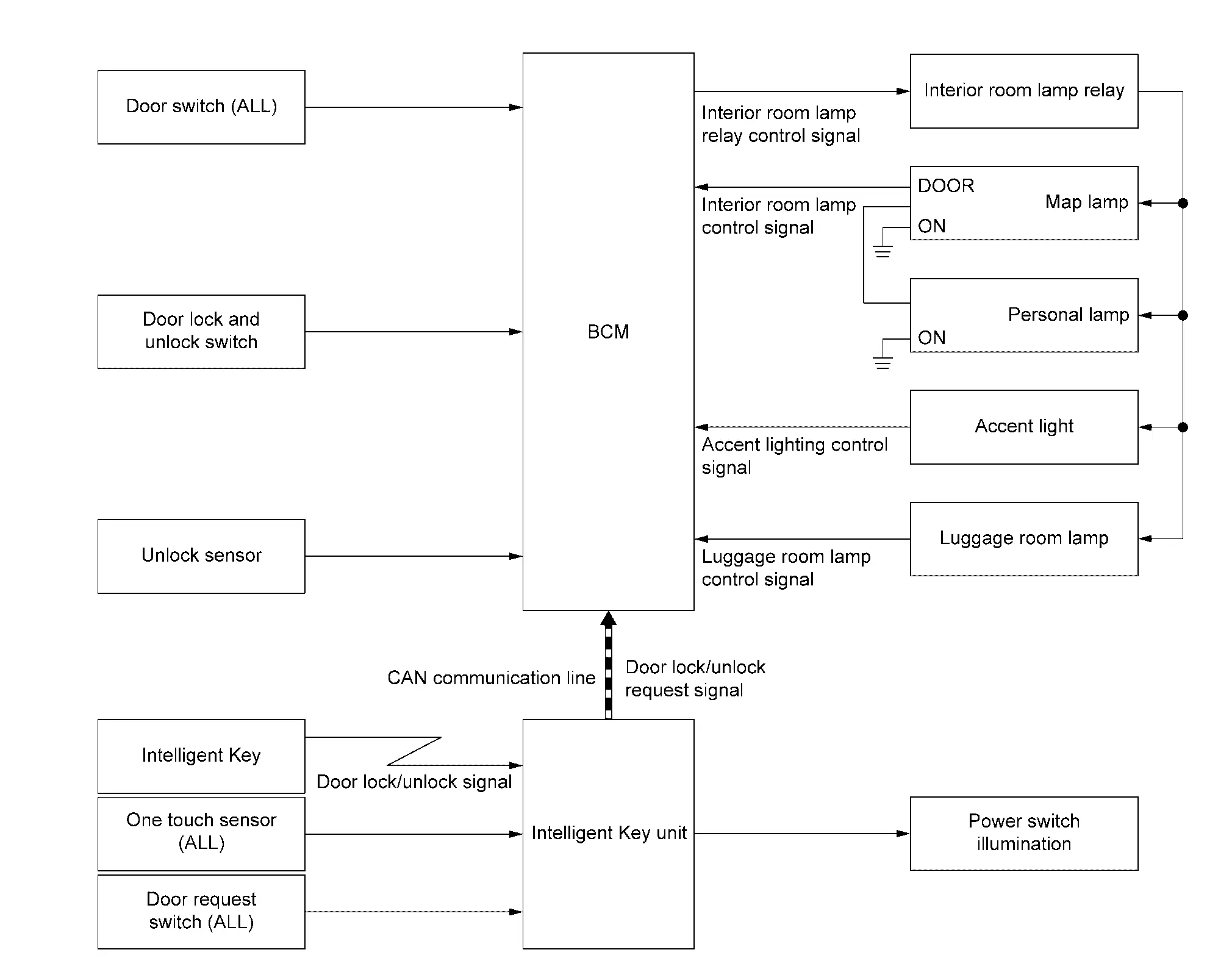
ComponentFunction
Door switch Detects the door condition (open or close), and inputs the door switch signal to BCM.
Door lock and unlock switch Transmits the door lock and unlock switch signal to BCM from door lock and unlock switch operation.
Unlock sensor Detects the front door lock (driver side) condition, and inputs the unlock sensor signal to BCM.
Intelligent Key Transmits the door lock/unlock signal to Intelligent Key unit from door lock/unlock button operation.
One touch sensor Detects the door lock/unlock operation from outside of the Nissan Ariya vehicle, and transmits the one touch sensor signal to Intelligent Key unit.
Door request switch Detects the door lock/unlock operation from outside of the Nissan Ariya vehicle, and transmits the door request switch signal to Intelligent Key unit.
BCM Controls the interior room lamp relay, and turns the each interior room lamp ON/OFF.
Intelligent Key unit
  • Transmits the door lock/unlock request signal to BCM (via CAN communication).

  • Turns the power switch illumination ON/OFF.

Interior room lamp relay Interior room lamp relay supplies power supply voltage to each interior room lamp according to the control signal from BCM.
Map lamp
  • Interior room lamp relay supplies power supply voltage to each lamps, and turns the each lamps ON/OFF.

  • Refer to Interior Lamp Appearance and Bulb Specifications.

Personal lamp
Accent light
Luggage room lamp
Power switch illumination
  • Intelligent Key unit supplies power supply voltage to power switch illumination, and turns the power switch illumination ON/OFF.

  • Refer to Interior Lamp Appearance and Bulb Specifications.

OUTLINE

  • Following lamps are controlled by interior room lamp timer control function of BCM.

    • Map lamp

    • Personal lamp

  • Accent light is controlled by accent lighting control function of BCM.

  • Power switch illumination is controlled by power switch illumination control function of Intelligent Key unit.

  • Luggage room lamp is controlled by luggage room lamp control function of BCM.

INTERIOR ROOM LAMP TIMER CONTROL

Interior Room Lamp Timer Basic Operation
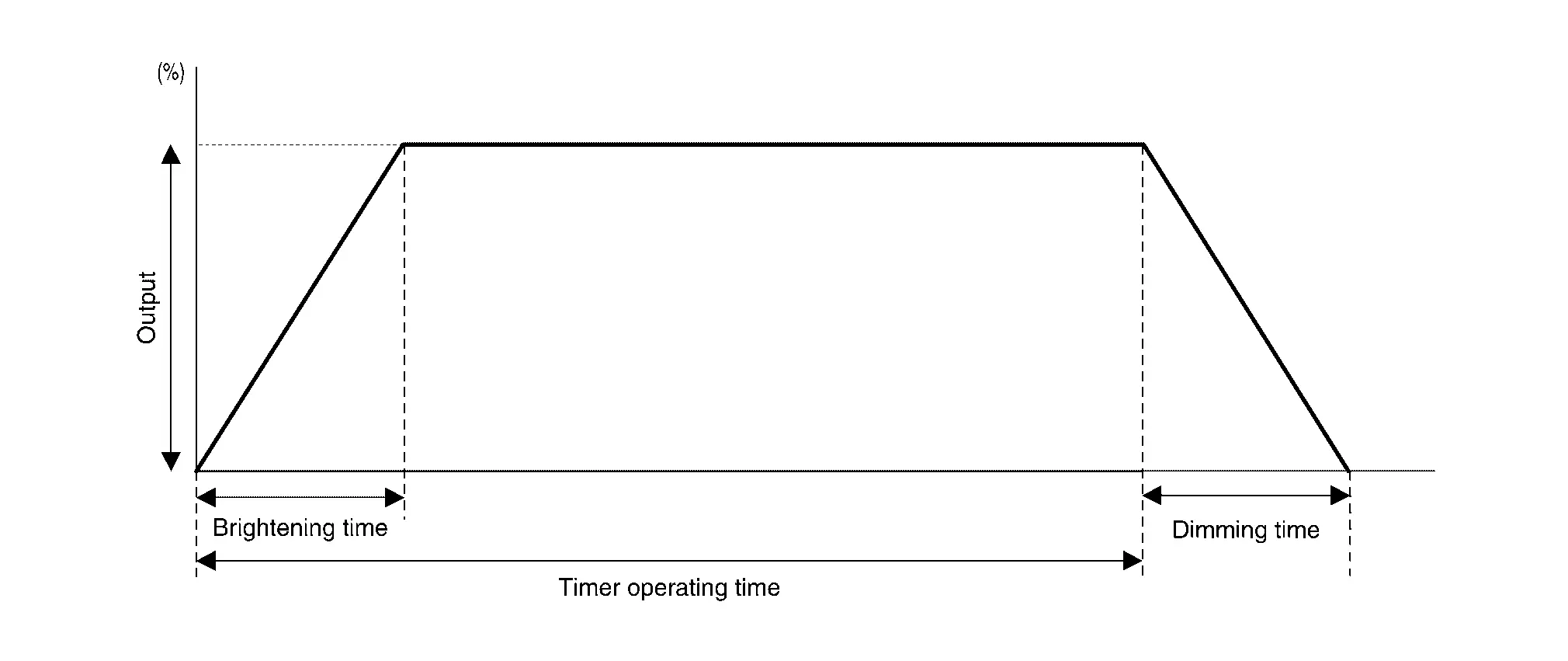
  • Interior room lamps turn ON and OFF (gradual brightening and dimming) by the interior room lamp timer.

  • Timer operating time is 20 seconds.

  • Brightening time is 2.8 second and dimming time is 1.5 seconds.

  • BCM judges the Nissan Ariya vehicle condition with the following items and activates the interior room lamp timer.

    • Power switch condition

    • Door switch signal (except back door)

    • Unlock sensor signal

    • Door lock/unlock signal

    • Door lock/unlock request signal

Interior Room Lamp ON Operation

  • BCM always turns the interior room lamp relay ON to turn on interior room lamp when any door opens (except back door).

  • BCM activates the interior room lamp timer in any of the following condition to turn the interior room lamp ON for 20 seconds.

    • Status of all doors (except back door) are OPEN → CLOSE

    • Power switch ON → OFF

    • Door unlock signal is detected when all doors (except back door) close

Interior Room Lamp OFF Operation

BCM stops the timer in any of the following condition to turn the interior room lamp OFF.

  • The timer operating time is expired

  • Power switch OFF → ON

  • Door lock signal is detected with all doors (except back door) close.

ACCENT LIGHTING CONTROL

  • BCM turns the accent light ON when any door (except back door) opens or any door unlock (except back door).

  • BCM turns dimming operation of the accent light when READY condition.

  • BCM turns the accent light OFF when all door (except back door) closes and door lock.

LUGGAGE ROOM LAMP CONTROL

  • BCM turns the luggage room lamp ON when back door is open (back door switch is ON).

  • BCM turns the luggage room lamp OFF when back door is close (back door switch is OFF).

POWER SWITCH ILLUMINATION CONTROL

  • BCM turns the power switch illumination ON when power switch is ON.

  • BCM turns the power switch illumination OFF when power switch is OFF.

Circuit Diagram

Interior Room Lamp Battery Saver System Nissan Ariya 2026

System Description

SYSTEM DIAGRAM
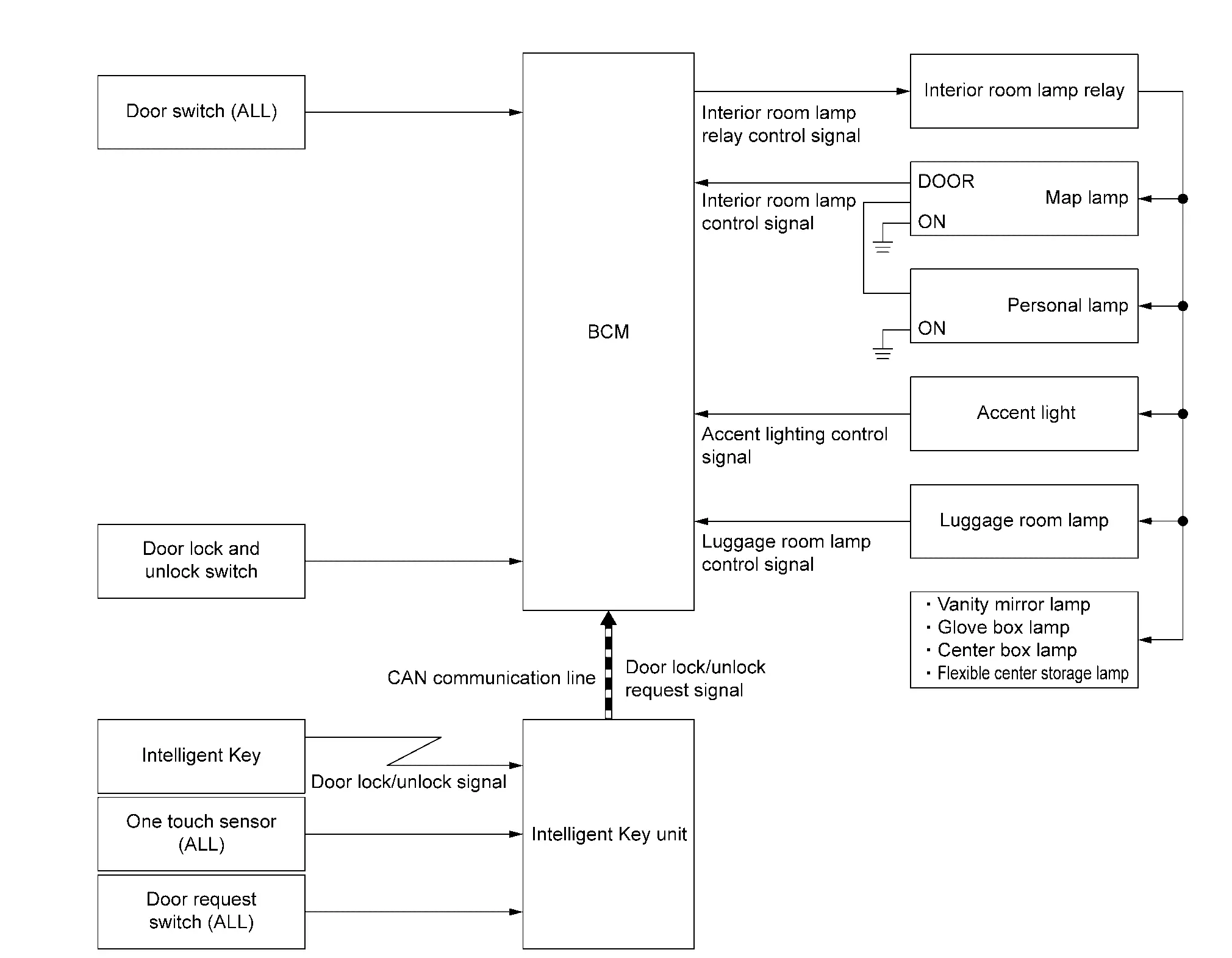
ComponentFunction
Door switch Detects the door condition (open or close), and inputs the door switch signal to BCM.
Door lock and unlock switch Transmits the door lock and unlock switch signal to BCM from door lock and unlock switch operation.
Intelligent Key Transmits the door lock/unlock signal to Intelligent Key unit from door lock/unlock button operation.
One touch sensor Detects the door lock/unlock operation from outside of the Nissan Ariya vehicle, and transmits the one touch sensor signal to Intelligent Key unit.
Door request switch Detects the door lock/unlock operation from outside of the Nissan Ariya vehicle, and transmits the door request switch signal to Intelligent Key unit.
BCM Controls the interior room lamp relay, and turns the each interior room lamp ON/OFF.
Intelligent Key unit Transmits the door lock/unlock request signal to BCM (via CAN communication).
Interior room lamp relay Interior room lamp relay supplies power supply voltage to each interior room lamp according to the control signal from BCM.
Map lamp
  • Interior room lamp relay supplies power supply voltage to each lamps, and turns the each lamps ON/OFF.

  • Refer to Interior Lamp Appearance and Bulb Specifications.

Personal lamp
Accent light
Luggage room lamp
Vanity mirror lamp
Glove box lamp
Center box lamp
Flexible center storage lamp

OUTLINE

  • Interior room lamp battery saver is controlled by BCM.

  • BCM turns interior room lamps OFF depending on the Nissan Ariya vehicle condition. This function prevent battery discharge if the driver neglects, turning OFF any lamps.

INTERIOR ROOM LAMP BATTERY SAVER FUNCTION

  • When the power switch is turned OFF, BCM operates timer for 10 minutes and then turns interior room lamp relay OFF to cut the interior room lamp power supply.

  • BCM restart the timer when any of the following signal changes while operating the timer.

    • Power switch condition

    • Door switch signal

    • Door lock/unlock signal

    • Door lock/unlock request signal

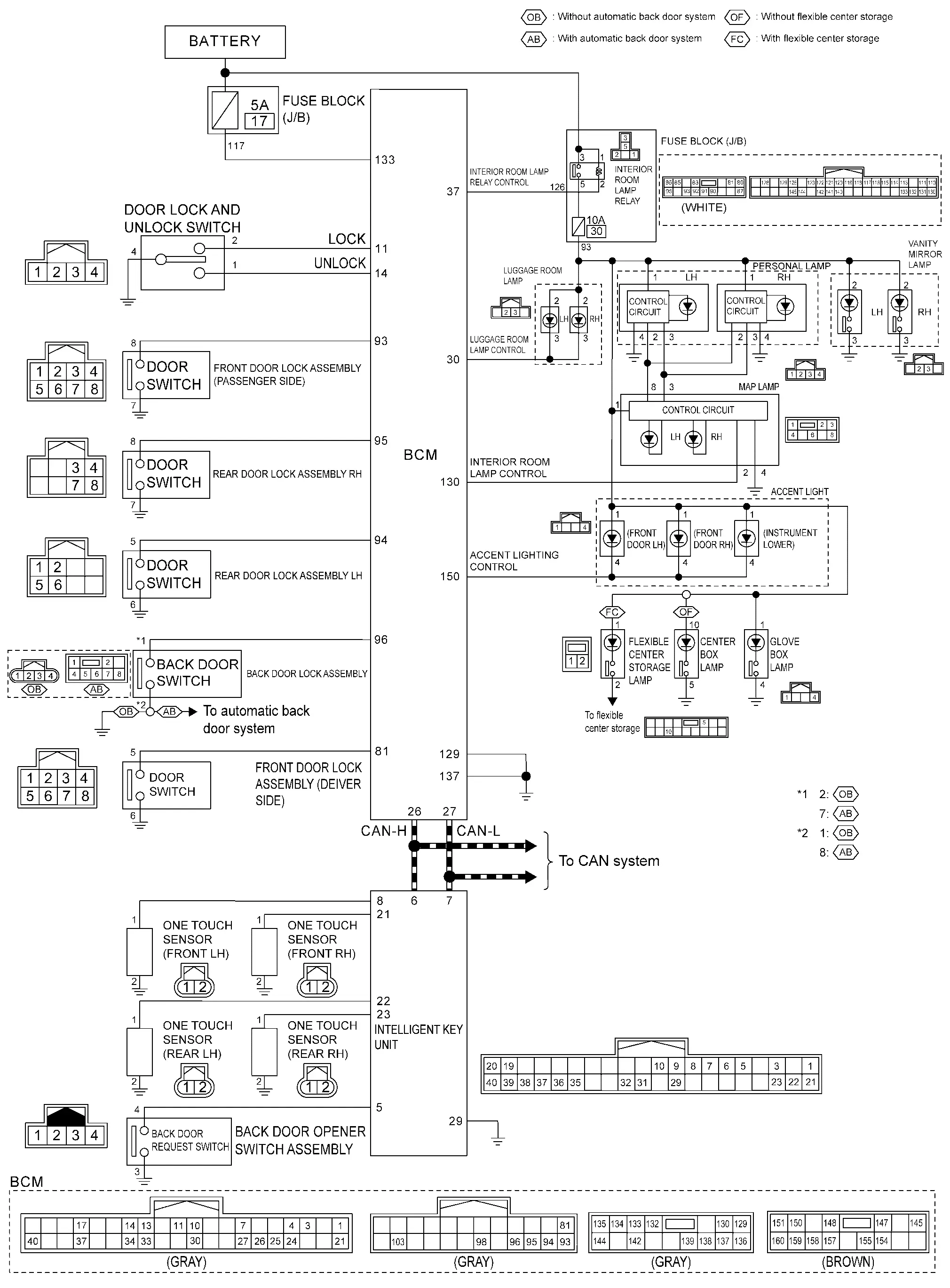
Circuit Diagram
Illumination Control System Nissan Ariya: FE0

System Description

SYSTEM DIAGRAM
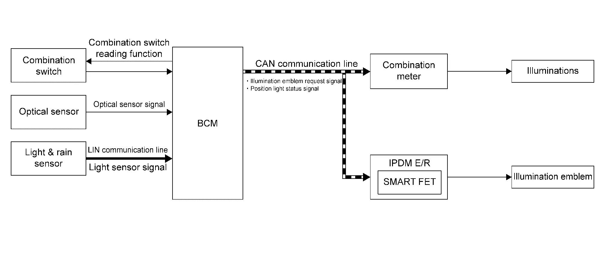
ComponentFunction
Combination switch Inputs the each switch condition signal to BCM.
Optical sensor*1 The optical sensor outputs voltage signals to the BCM according to the brightness of the ambient light.
Light & rain sensor*2 The light & rain sensor transmits light sensor signal to the BCM (via LIN communication) according to the brightness of the ambient light.
BCM
  • Detects each switch condition by the combination switch reading function.

  • Inputs the optical sensor signal from optical sensor.

  • Receives the light sensor signal from light & rain sensor.

  • Transmits the position light status signal to combination meter.

  • Transmits the illumination emblem request signal to IPDM E/R.

IPDM E/R Controls integrated smart FET according to the request from BCM.
Combination meter Turns ON/OFF the illuminations according to the status from BCM.
Illuminations Combination meter supplies power supply voltage to each illuminations, and turns ON/OFF the each illuminations.
Illumination emblem IPDM E/R supplies power supply voltage to illumination emblem, and turns ON/OFF the illumination emblem.

*1: With optical sensor

*2: With light & rain sensor

OUTLINE

Each illumination lamp is controlled by each function of BCM, IPDM E/R and combination meter.

Control by BCM

  • Combination switch reading function

  • Illumination emblem control function

  • Auto light function (intelligent auto light system)

Control by IPDM E/R

Smart FET control function

Control by Combination Meter

Illumination control function

ILLUMINATION CONTROL

  • BCM detects the combination switch condition with the combination switch reading function.

  • BCM transmits illumination emblem request signal to IPDM E/R according to set the Nissan Ariya vehicle to READY or tail lamp ON condition.

  • BCM transmits position light status signal to combination meter according to tail lamp ON condition.

  • IPDM E/R turns the integrated smart FET ON according to illumination emblem request signal and provides the power supply to illumination emblem.

  • Combination meter turns ON the illuminations according to position light status signal.

Circuit Diagram

Fail-safe

CAN COMMUNICATION CONTROL

When CAN communication with BCM is impossible, IPDM E/R performs fail-safe control. After CAN communication recovers normally, it also returns to normal control.

If No CAN Communication Is Available With BCM

Control partFail-safe operation
Illumination emblem The status just before activation of fail-safe is maintained.

Advanced Ambient Lighting System Nissan Ariya SUV

System Description

SYSTEM DIAGRAM
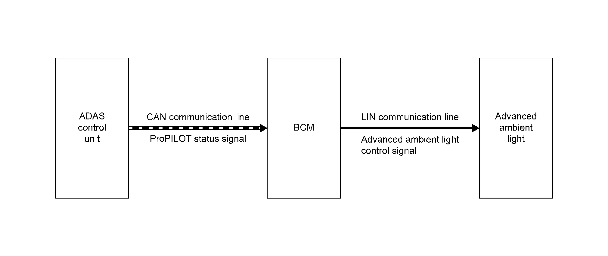
ComponentFunction
ADAS control unit 2 Transmits the ProPILOT status signal to BCM (via CAN communication).
BCM Transmits the advanced ambient light control signal to advanced ambient light (via LIN communication) according to the ProPILOT status signal from ADAS control unit 2.
Advanced ambient light Turn ON/OFF and changes color the advanced ambient light, according to advanced ambient light control signal from BCM (via LIN communication).

OUTLINE

Advanced ambient lighting system is controlled by advanced ambient lighting control function of BCM and ProPILOT control function of ADAS control unit 2.

ADVANCED AMBIENT LIGHTING CONTROL

  • ADAS control unit 2 transmits the ProPILOT status signal to BCM (via CAN communication) according to ProPILOT Assist operation condition.

  • BCM transmits the advanced ambient light control signal to advanced ambient light (via LIN communication) according to the ProPILOT status signal from ADAS control unit 2.

  • Advance ambient light turns ON/OFF and changes color according to advanced ambient light control signal.

  • For details, advance ambient light condition and ProPILOT Assist operation condition. Refer to System Description.

Circuit Diagram
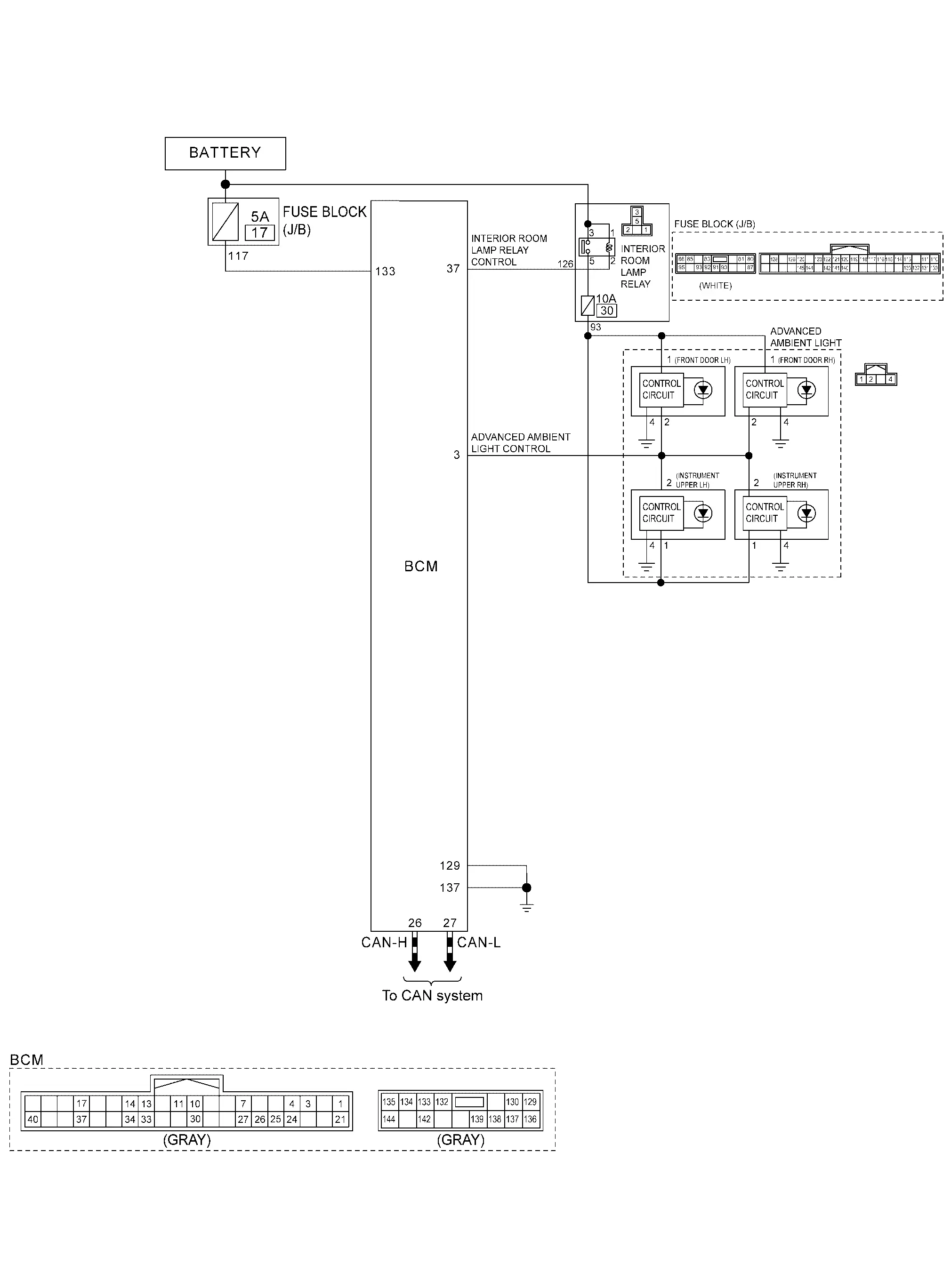
Fail-safe

FAIL-SAFE CONTROL BY DTC

BCM performs fail-safe control when any DTC are detected.

Display contents of CONSULTFail-safe
B2C76-04: Ambient light 1 Advanced ambient light (instrument upper RH) OFF or dimmed lighting.
B2C77-04: Ambient light 2 Advanced ambient light (instrument upper LH) OFF or dimmed lighting.
B2C78-04: Ambient light 3 Advanced ambient light (front door RH) OFF or dimmed lighting.
B2C79-04: Ambient light 4 Advanced ambient light (front door LH) OFF or dimmed lighting.