Removal and Installation
- Li-Ion Battery. 2wd
Li-Ion Battery. 2wd Nissan Ariya: FE0
Exploded View

 |
Li-ion battery |  |
Li-ion battery under cover (center) |  |
Clip |
 |
Li-ion battery under cover (rear) bracket right |  |
Li-ion battery under cover (rear) bracket left |  |
Li-ion battery under cover (rear) |
 |
Li-ion battery under cover (center right) |  |
Li-ion battery under cover (center left) |  |
Li-ion battery under cover (front) |
 |
Li-ion battery under cover (front right) bracket |  |
Li-ion battery under cover (front left) bracket |  |
Li-ion battery under cover (front right) |
 |
Li-ion battery under cover (front left) |  |
Li-ion battery under cover (front right) lid |  |
Li-ion battery under cover (front left) lid |
 |
: N·m (kg-m, in-lb) | ||||
 |
: N·m (kg-m, ft-lb) |
Removal & Installation
DANGER: Because hybrid vehicles and electric vehicles contain a high voltage battery, there is a risk of electric shock, electric leakage, or similar accidents if the Nissan Ariya vehicle is handled incorrectly. Be sure to follow the correct work procedures when performing inspection and maintenance.
REMOVAL
Remove Li-ion battery under cover (front right) lid and Li-ion battery under cover (front left) lid.
Lift up Nissan Ariya vehicle and remove front under cover rear , Li-ion battery under cover (front) right & left , and Li-ion battery under cover (front) . Refer to Exploded View and Exploded View.

 |
: Nissan Ariya Vehicle front |
Remove remaining Li-ion battery covers. Refer to Exploded View.
Remove rear diffuser. Refer to Removal & Installation.
Remove console box rear finisher.
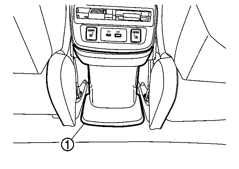
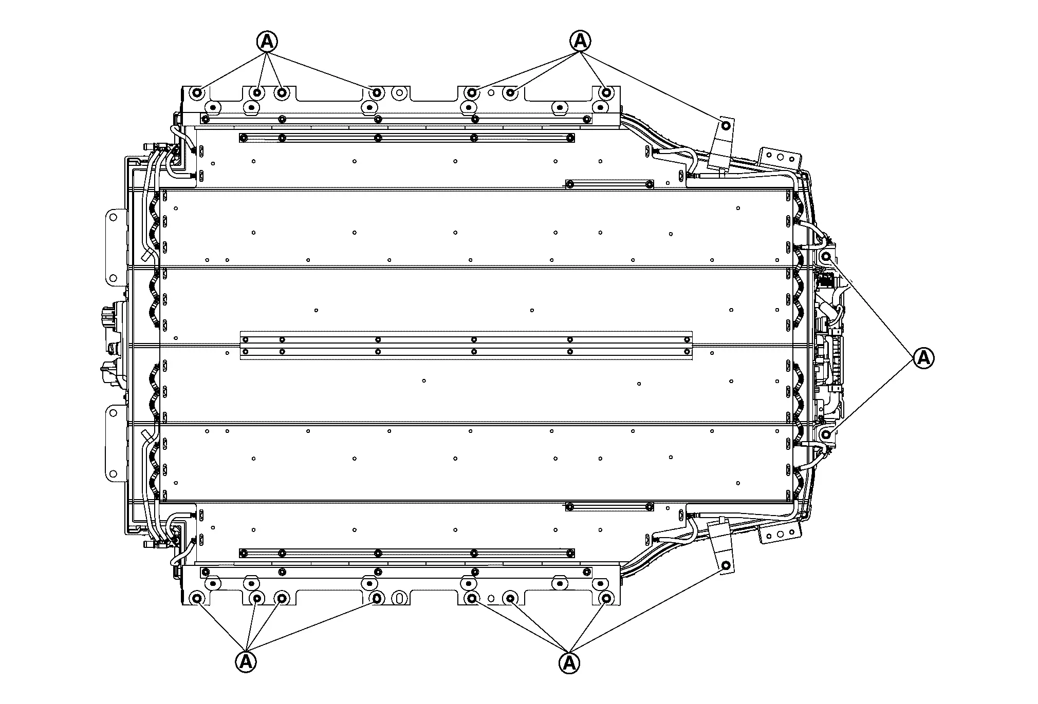
Turn over floor carpet and remove Li-ion battery mounting bolts  .

Remove Li-ion battery side of water hose and drain high voltage coolant from Li-ion cooling system. Refer to COOLANT : Draining.
Remove high voltage harness (FR) bracket mounting bolt .
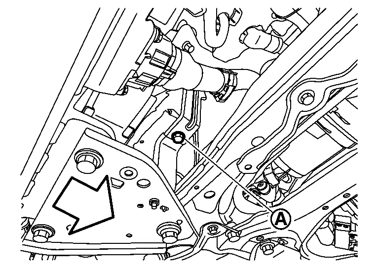
|
: Nissan Ariya Vehicle |
Remove high voltage harness (FR) connector .
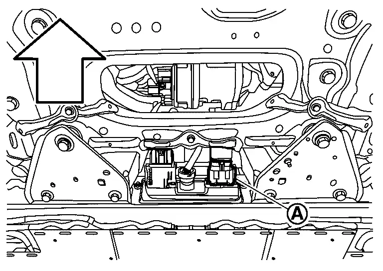
|
: Nissan Ariya Vehicle |
- There is the danger of electric shock caused by contact with the terminals. Be sure to wear insulated protective gear.


- Because there is the danger of electric shock, immediately insulate disconnected high voltage connectors and terminals with insulating tape.
Disconnect high voltage harness (FR) connector according to the following procedure.
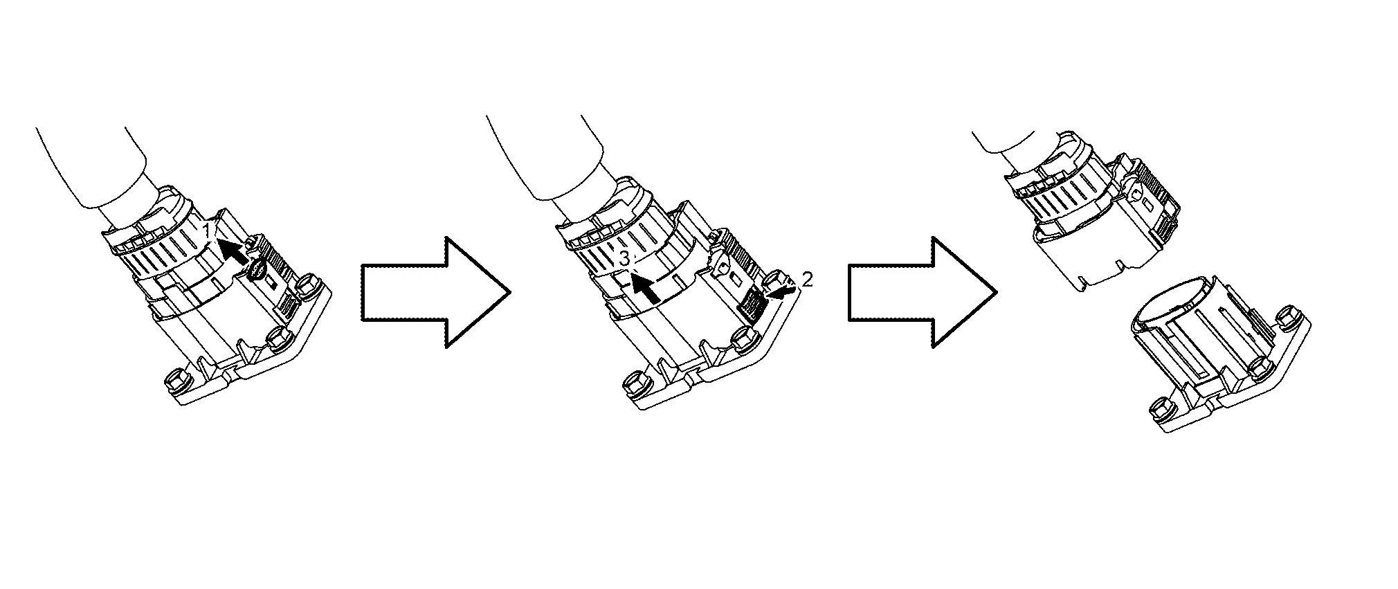
Remove Nissan Ariya vehicle communication harness connector of Li-ion battery by turning it counterclockwise.
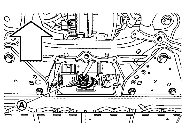
|
: Nissan Ariya Vehicle |
Remove high voltage harness (quick charge) connector .
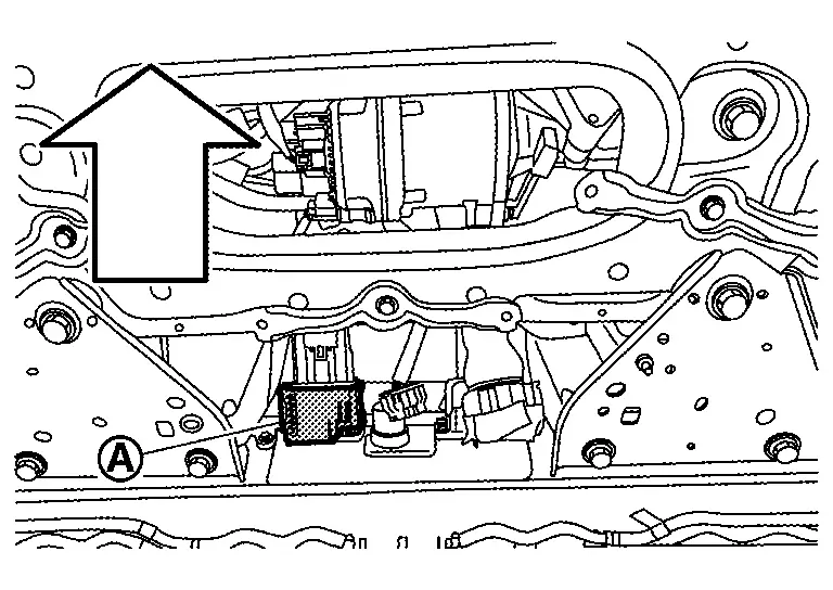
|
: Nissan Ariya Vehicle |
- There is the danger of electric shock caused by contact with the terminals. Be sure to wear insulated protective gear.
- Because there is the danger of electric shock, immediately insulate disconnected high voltage connectors and terminals with insulating tape.
Remove high voltage harness (quick charge) connector by the following procedure.

Remove left member stay (Rear side). Refer to REAR SUSPENSION MEMBER : Removal & Installation.

|
: Nissan Ariya Vehicle |
Install left member stay (Rear side) mounting bolt while left member stay (Rear side) is removed. Refer to REAR SUSPENSION MEMBER : Removal & Installation.
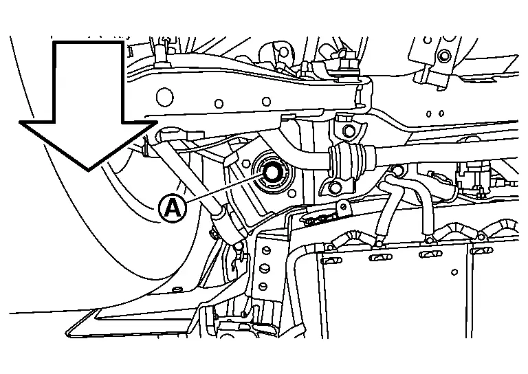
|
: Nissan Ariya Vehicle |
Remove right member stay (Rear side) . Refer to REAR SUSPENSION MEMBER : Removal & Installation.
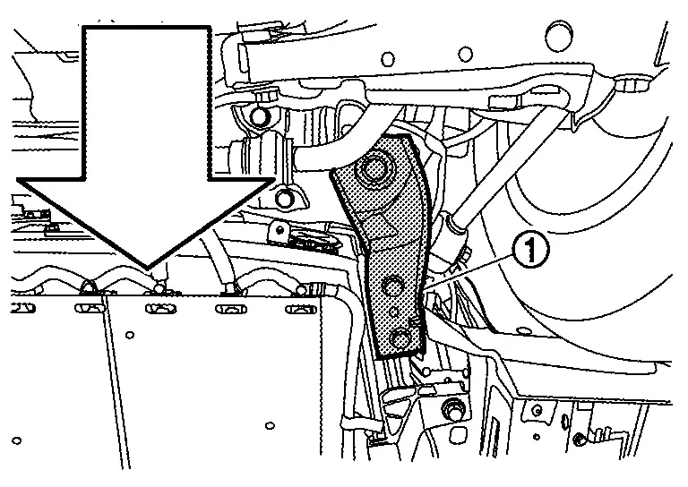
|
: Nissan Ariya Vehicle |
Install right member stay (Rear side) mounting bolt while right member stay (Rear side) is removed. Refer to REAR SUSPENSION MEMBER : Removal & Installation.
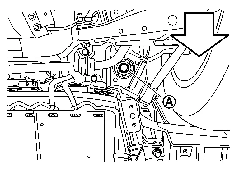
|
: Nissan Ariya Vehicle |
Remove left member stay (Front side) . Refer to FRONT SUSPENSION MEMBER : Removal & Installation.
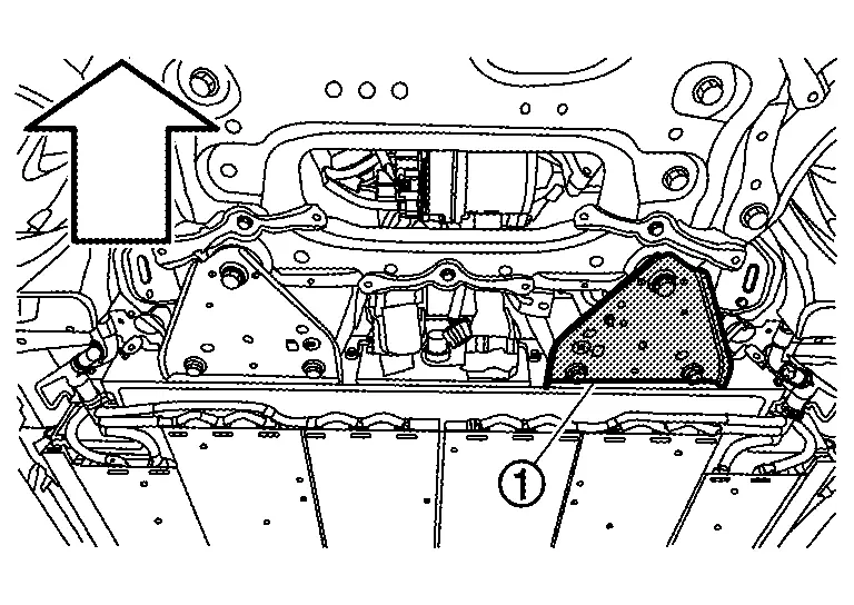
|
: Nissan Ariya Vehicle |
Install left member stay (Front side) mounting bolt while left member stay (Front side) is removed. Refer to FRONT SUSPENSION MEMBER : Removal & Installation.
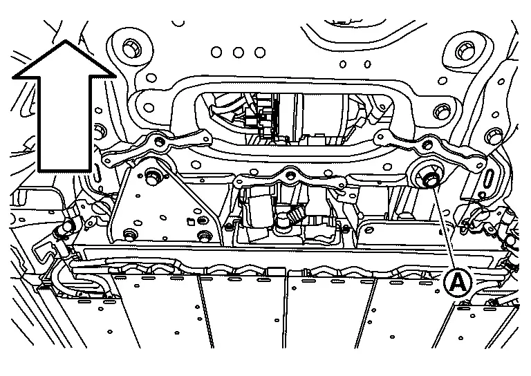
|
: Nissan Ariya Vehicle |
Remove right member stay (Front side) . Refer to FRONT SUSPENSION MEMBER : Removal & Installation.
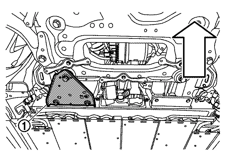
|
: Nissan Ariya Vehicle |
Install right member stay (Front side) mounting bolt while right member stay (Front side) is removed. Refer to FRONT SUSPENSION MEMBER : Removal & Installation.
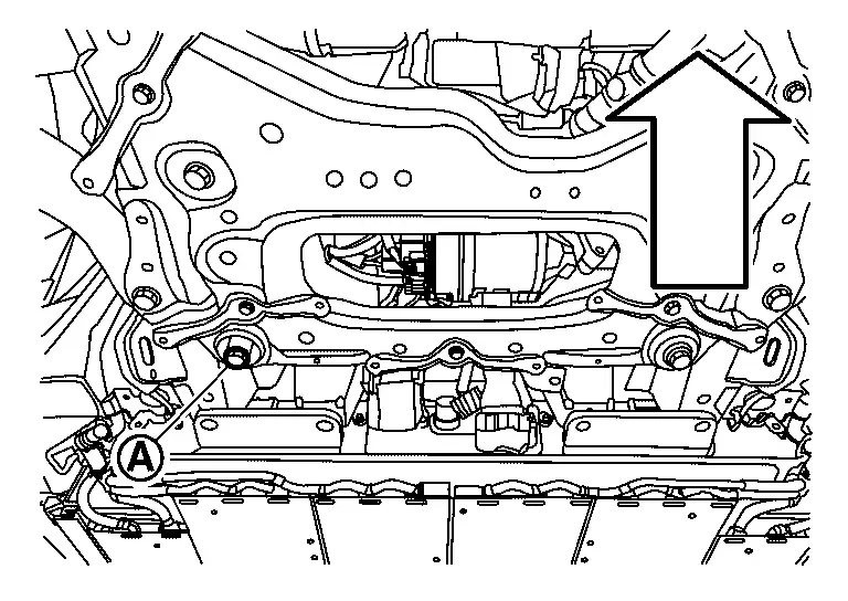
|
: Nissan Ariya Vehicle |
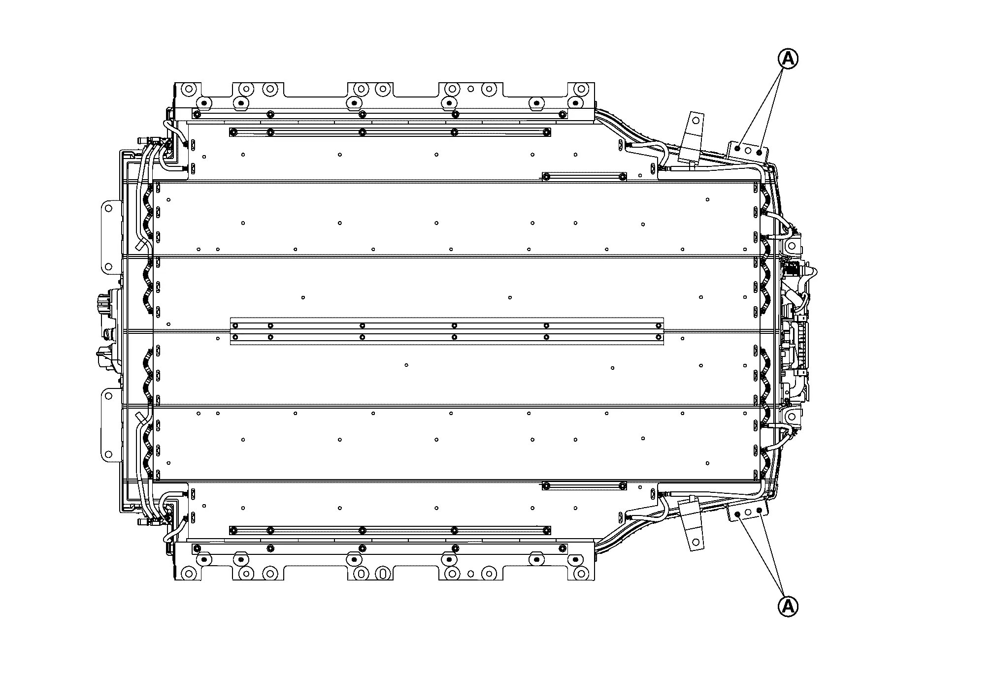
Remove right and left rear diffuser brackets .
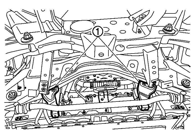
Remove stabilizer clamp and move stabilizer bar. Refer to REAR STABILIZER : Removal & Installation.
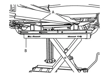
Install a battery support fixture [B (SST: NI-53360)] and bolts to the lift table [C (SST: NI-53034)].
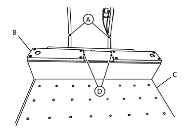
Install a battery support fixture (A) and bolts to the lift table (C).

Position the lift table with the battery support fixtures (A) under the Nissan Ariya vehicle.
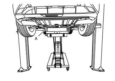
Align the rearward positioning channel  with the rearward end of the Li-ion battery center line ridges front-to-back and side-to-side.
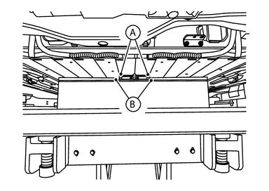
Align the positioning channels with the the Li-ion battery center line ridges front-to-back and side-to-side.
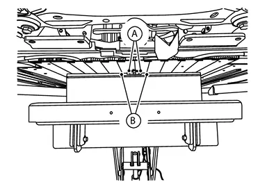
Raise the lift table with the battery support fixtures and support the Li-ion battery.
Remove the locate pins .
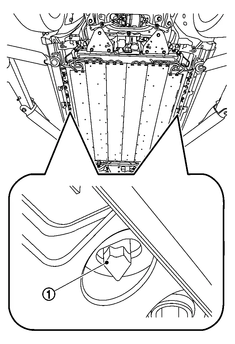
Remove the bolts from the Li-ion battery.
Lower the lift table and remove the Li-ion battery from the Nissan Ariya vehicle.
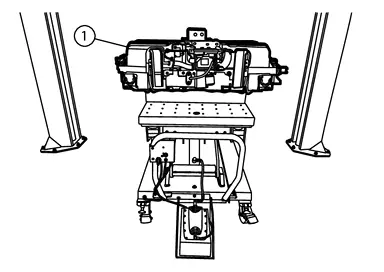
NECESSARY REMOVAL WORK WHEN Li-ion BATTERY IS REPLACED
In a separate two post above ground hoist, position the lift arm alignment mat [A (SST: NI-53033-MAT)] on the floor with the center dashed line  between the hoist lift posts.

 |
: Front of Li-ion battery |
|
: Guide circle |
Position the four hoist lift pads in the center of each circle .

Raise the hoist lift arms up to full height.
Remove the lift arm alignment mat.
Position the lift table (F) with the battery support fixtures and the Li-ion battery under the hoist lift arms.
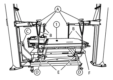
Position the lifting beams [E (SST: NI-53033-1)] under the Li-ion battery and in-between the battery support fixtures.
Install the lifting straps [B (SST: NI-53033-STRAP)] to the hoist arms.
Install the lifting straps to the lifting beams.
Remove the Li-ion battery from the battery support fixtures using the hoist lift.
Lower the Li-ion battery into an approved shipping container.
NECESSARY INSTALLATION WORK WHEN Li-ion BATTERY IS REPLACED
In a separate two post above ground hoist, position the lift arm alignment mat [A (SST: NI-53033-MAT)] on the floor with the center dashed line between the hoist lift posts.
|
: Front of Li-ion battery |
|
: Guide circle |
Position the four hoist lift pads in the center of each circle .
Raise the hoist lift arms up to full height.
Remove the lift arm alignment mat.
Position the new Li-ion battery under the hoist lift arms.
Position the lifting beams (SST: NI-53033-1) under the new Li-ion battery.
Install the lifting straps (SST: NI-53033-STRAP) to the hoist arms.
Install the lifting straps to the lifting beams.
Raise the new Li-ion battery using the hoist lift.
Install a battery support fixture [B (SST: NI-53360)] and bolts to the lift table [C (SST: NI-53034)].
Install a battery support fixture (A) and bolts to the lift table (C).
Position the lift table with the battery support fixtures under the new Li-ion battery. Align the rearward positioning channel with the rearward end of the Li-ion battery center line ridges. Align the forward positioning channel with the forward end of the Li-ion battery center line ridges. Adjust the length of the lift table to align the forward battery support fixture with the forward end of the Li-ion battery center line ridges.
Lower the hoist lift arms to lower the new Li-ion battery onto the lift table with the battery support fixtures.
Remove the lifting straps and the lifting beams.
Necessary work when Li-ion battery is replaced
Remove cover and frame of battery palette.
When changing Li-ion battery into new one, perform the following procedure.
Write date of replacement in EV battery tracking identification sticker packed with new spare parts.
Separate EV battery tracking identification sticker into two pieces and stick them to old Li-ion battery body that was replaced and "Li-ion battery replacement history record" respectively.
Fill the required items out " Li-Ion battery replacement history record".
Remove cover for battery palette locate pin.
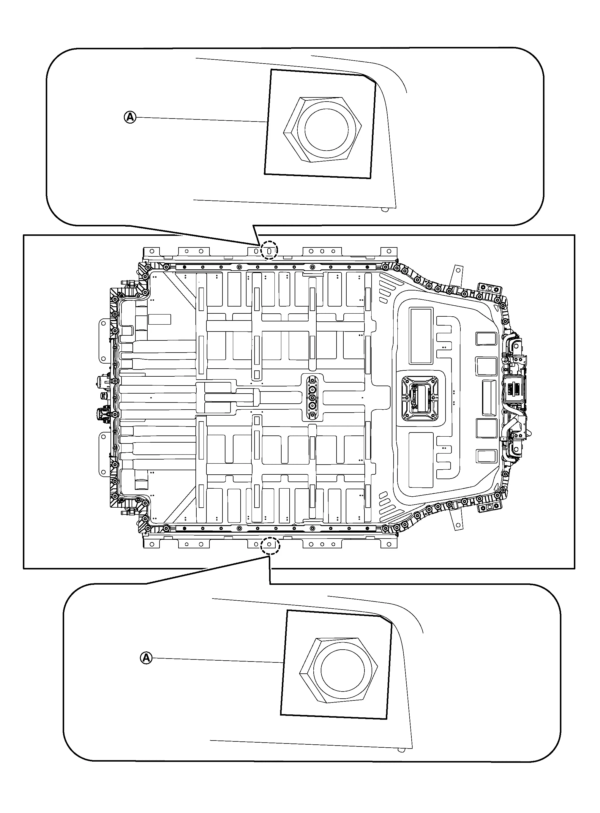
INSTALLATION
Install the LiB assembly installation guide pins [SST: KV99119500 (NI-53347)](A) to the locate pin holes in the Nissan Ariya vehicle body.
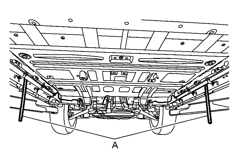
Position the lift table (SST: NI-53034) with the battery support fixtures (SST: NI-53359) and the Li-ion battery under the Nissan Ariya vehicle body.
Align LiB assembly installation guide pins [SST: KV99119500 (NI-53347)] (A) with holes of Li-ion battery.
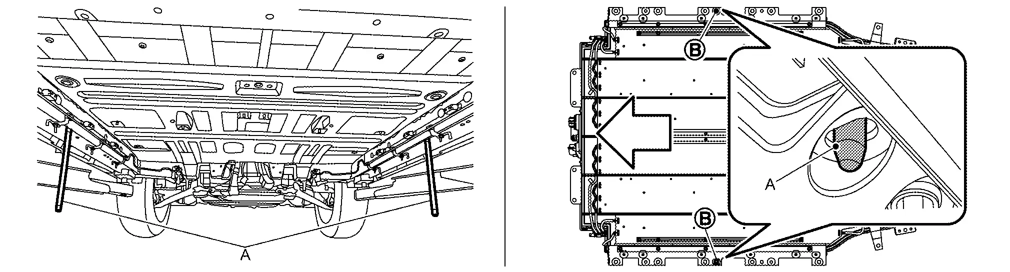
|
: Nissan Ariya Vehicle front |
Raise the lift table (B) with the battery support fixtures (A) and the Li-ion battery. Adjust the position of the lift table so that the holes in the Li-ion battery align with the LiB assembly installation guide pins.
Remove LiB assembly installation guide pins [SST: NI-53347] from Nissan Ariya vehicle and install locate pin of vehicle side.
Tighten mounting bolts of Li-ion battery to the specified torque and remove lift table.
Install rear stabilizer. Refer to REAR STABILIZER : Removal & Installation.
Install right and left rear diffuser brackets .
Install Li-ion side only of water hose. Refer to COOLANT : Draining.
Remove mounting bolt of right member stay (Front side). Refer to FRONT SUSPENSION MEMBER : Removal & Installation.
|
: Nissan Ariya Vehicle front |
Install right member stay (Front side) .
|
: Nissan Ariya Vehicle front |
Remove mounting bolt of left member stay (Front side). Refer to FRONT SUSPENSION MEMBER : Removal & Installation.
|
: Nissan Ariya Vehicle front |
Install left member stay (Front side) .
|
: Nissan Ariya Vehicle front |
Remove mounting bolt of right member stay (Rear side). Refer to REAR SUSPENSION MEMBER : Removal & Installation.
|
: Nissan Ariya Vehicle front |
Install right member stay (Rear side) . Refer to REAR SUSPENSION MEMBER : Removal & Installation.
|
: Nissan Ariya Vehicle front |
Cut metal plate
next to the nut using nippers (B).Do not use tools that generate sparks or fire, such as power tools.
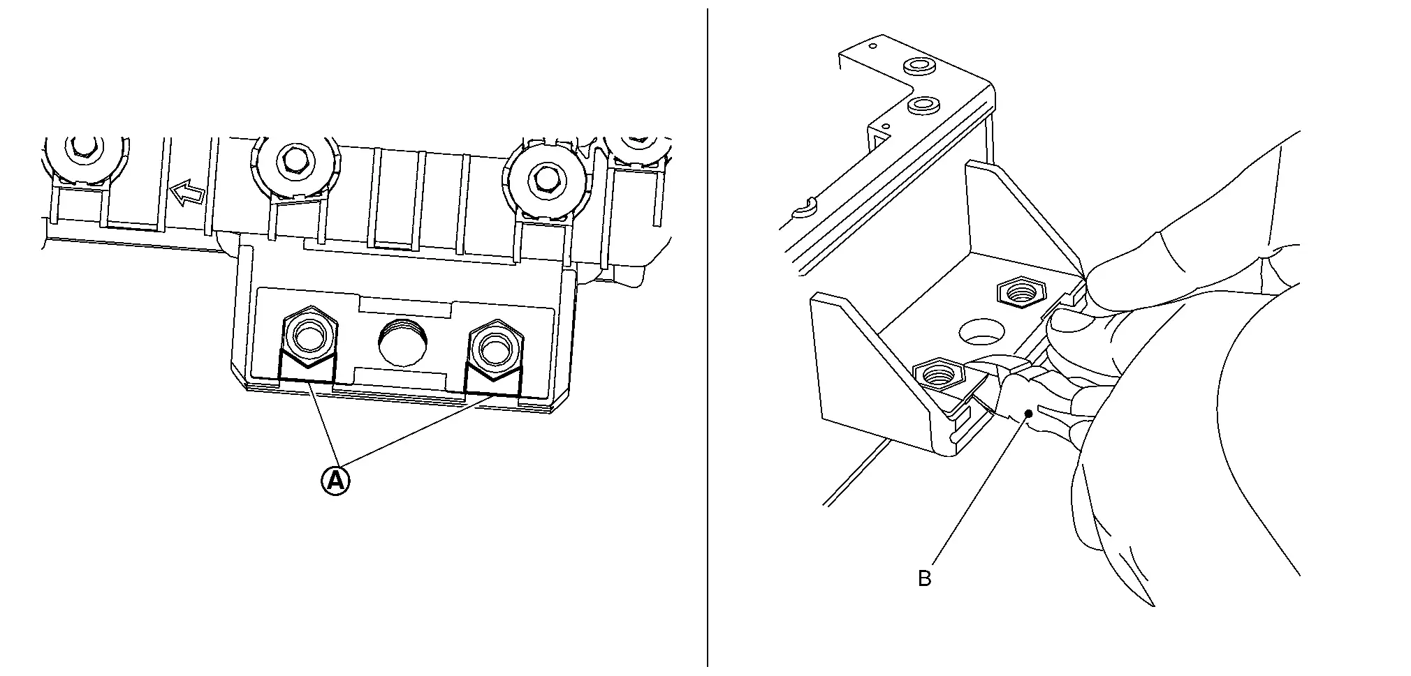
Slide nuts
to the arrow direction and remove them from Li-ion battery.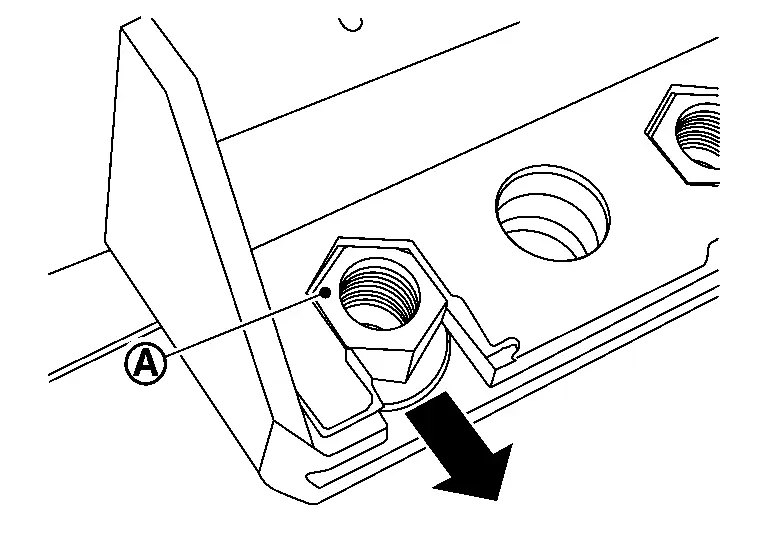
Slide new nut
to the arrow direction and install it from Li-ion battery.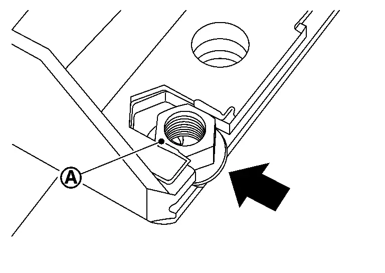
Remove mounting bolt of left member stay (Rear side). Refer to REAR SUSPENSION MEMBER : Removal & Installation.
|
: Nissan Ariya Vehicle front |
Install left member stay (Rear side). Refer to REAR SUSPENSION MEMBER : Removal & Installation.
|
: Nissan Ariya Vehicle front |
Install high voltage harness connector of quick charge port.
|
: Nissan Ariya Vehicle front |
- There is the danger of electric shock caused by contact with the terminals. Be sure to wear insulated protective gear.
Install high voltage harness connector of quick charge port according to the following procedure.

Install Nissan Ariya vehicle communication connector of Li-ion battery while turning the connector clockwise.

|
: Nissan Ariya Vehicle front |
Install high voltage harness connector of quick charge port.
|
: Nissan Ariya Vehicle front |
- There is the danger of electric shock caused by contact with the terminals. Be sure to wear insulated protective gear.
Install high voltage connector according to the following procedure.
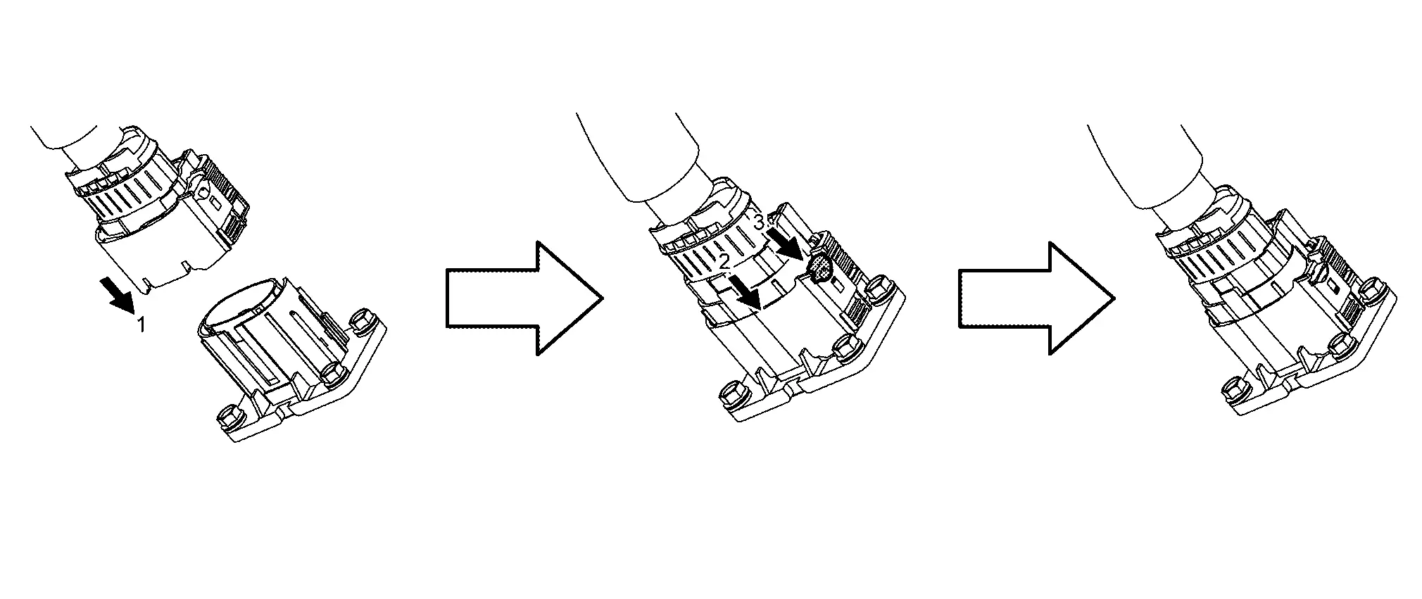
Install high voltage harness bracket mounting bolt of quick charge port.
|
: Nissan Ariya Vehicle front |
Install in the reverse order of removal.
Inspection
Equipotential inspection
After installing battery pack to vehicle, measure resistance between battery pack ground bolt and body ground.
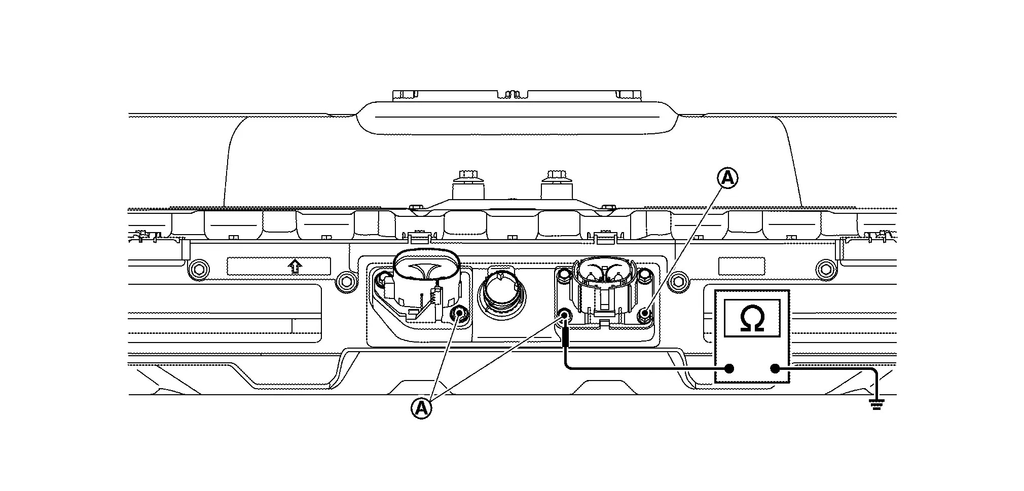
| Specified value | :less than 0.05 Ω |
If measured value deviates from the specified value, check ground bolts & for installation and tightening.

|
: Left front frame |
 |
: Li-ion battery bottom |
|
Nissan Ariya Vehicle front |