Precautions
- Precautions
- Cautions as to High Voltage
- Procedure for Park Lock Release
- Lifting Point
- Tow Truck Towing
Precautions Nissan Ariya 2023
DESCRIPTION : Precautions
Observe the following precautions to ensure safe and proper servicing. These precautions are not described in each individual section.
PRECAUTIONS FOR SUPPLEMENTAL RESTRAINT SYSTEM (SRS) AIR BAG AND SEAT BELT PRE-TENSIONER : Precautions
The Supplemental Restraint System such as “AIR BAG” and “SEAT BELT PRE-TENSIONER”, used along with a front seat belt, helps to reduce the risk or severity of injury to the driver and front passenger for certain types of collision.
Information necessary to service the system safely is included in the “SRS AIR BAG” and “SEAT BELT” of this Service Manual.
To avoid rendering the SRS inoperative, which could increase the risk of personal injury or death in the event of a collision that would result in air bag inflation, it is recommended that all maintenance and repair be performed by an authorized NISSAN/INFINITI dealer.
Improper repair, including incorrect removal and installation of the SRS, can lead to personal injury caused by unintentional activation of the system. For removal of Spiral Cable and Air Bag Module, see “SRS AIR BAG”.
Never use electrical test equipment on any circuit related to the SRS unless instructed to in this Service Manual. SRS wiring harnesses can be identified by yellow and/or orange harnesses or harness connectors.
PRECAUTIONS WHEN USING POWER TOOLS (AIR OR ELECTRIC) AND HAMMERS
When working near the Air Bag Diagnosis Sensor Unit or other Air Bag System sensors with the ignition/power switch ON or engine running, never use air or electric power tools or strike near the sensor(s) with a hammer. Heavy vibration could activate the sensor(s) and deploy the air bag(s), possibly causing serious injury.
When using air or electric power tools or hammers, always switch the ignition/power switch OFF, disconnect the 12V battery or batteries, and wait at least 3 minutes before performing any service.
PRECAUTIONS FOR PROCEDURE WITHOUT COWL TOP COVER : Precautions
When performing the procedure after removing cowl top cover, cover the lower end of windshield with urethane, etc to prevent damage to windshield.

PRECAUTIONS CONCERNING ON-BOARD SERVICING OF EV SYSTEMS : Precautions
Also, lock hood unless necessary to prevent 12V battery voltage from dropping.
PRECAUTIONS FOR REMOVING BATTERY TERMINAL : Precautions
With the adoption of Auto ACC function, ACC power is automatically supplied by operating the Intelligent Key or remote keyless entry or by opening/closing the driver side door. In addition, ACC power is supplied even after the ignition switch is turned to the OFF position, i.e. ACC power is supplied for a certain fixed time.
When disconnecting the 12V battery terminal, turn off the ACC power before disconnecting the 12V battery terminal, observing “How to disconnect 12V battery terminal” described below.
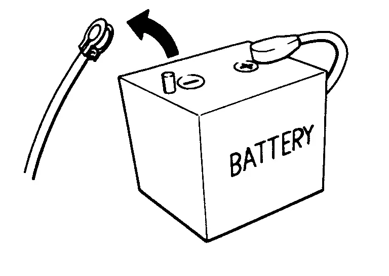
Always disconnect the battery terminal within 60 minutes after turning OFF the power switch. Even when the power switch is OFF, the 12V battery automatic charge control may automatically start after a lapse of 60 minutes from power switch OFF.
Disconnect 12V battery terminal according to the following steps.
WORK PROCEDURE
Open the hood (LHD models) or the back door (RHD models).
Check that charge cable (including EVSE) is not connected to the charge port.
Turn the power switch OFF → ON → press the power switch for at least 2 seconds to turn the high voltage system OFF, and then check that the charging status indicator is not illuminated.
Get out of the Nissan Ariya vehicle. Close all doors {except the hood (LHD models) or the back door (RHD models)}.
Check that the combination meter turns OFF and wait for 5 minutes or more.
Check that the followings are not illuminated.
Charging status indicator
Electric parking brake warning lamp
Remove 12V battery terminal within 60 minutes after the power switch is turned OFF at Step 3.
For vehicles with the 2-batteries, be sure to connect the main battery and the sub battery before turning ON the power switch.
After installing the 12V battery, always check "Self Diagnosis Result" of all ECUs and erase DTC.
Cautions as to High Voltage Nissan Ariya first Gen
PRECAUTIONS FOR HIGH VOLTAGE : Precautions
DANGER: Since hybrid vehicles and electric vehicles contain a high voltage battery, there is the risk of electric shock, electric leakage, or similar accidents resulting in death or severe injury, if high voltage components and Nissan Ariya vehicle are mishandled. When performing an inspection or maintenance, be sure to comply with the instructions below to perform correct work procedures.
POINT TO BE CHECKED BEFORE STARTING MAINTENANCE WORK
The high voltage system may starts automatically. It is required to check that the charge cable (including EVSE) is not connected to charge port before starting maintenance work.
HIGH VOLTAGE HARNESS AND EQUIPMENT IDENTIFICATION
All the high voltage harnesses and connectors are orange. The Li-ion battery and other high voltage devices include an orange high voltage label. Never touch these harnesses and high voltage parts.
HANDLING OF HIGH VOLTAGE HARNESS AND TERMINALS
Immediately insulate disconnected high voltage connectors and terminals with insulating tape.
GUIDELINES ON WORKERS WITH MEDICAL ELECTRONICS
PROHIBITED ITEMS TO CARRY DURING THE WORK
Hybrid vehicles and electric vehicles contain parts with high voltage and intense magnetic force. Never carry metal products and magnetic recording media (e.g. credit card, debit card) to repair/inspect high voltage parts. If this is not observed, the metal products may create a risk of short circuit and the magnetic recording media may lose their magnetic recording.
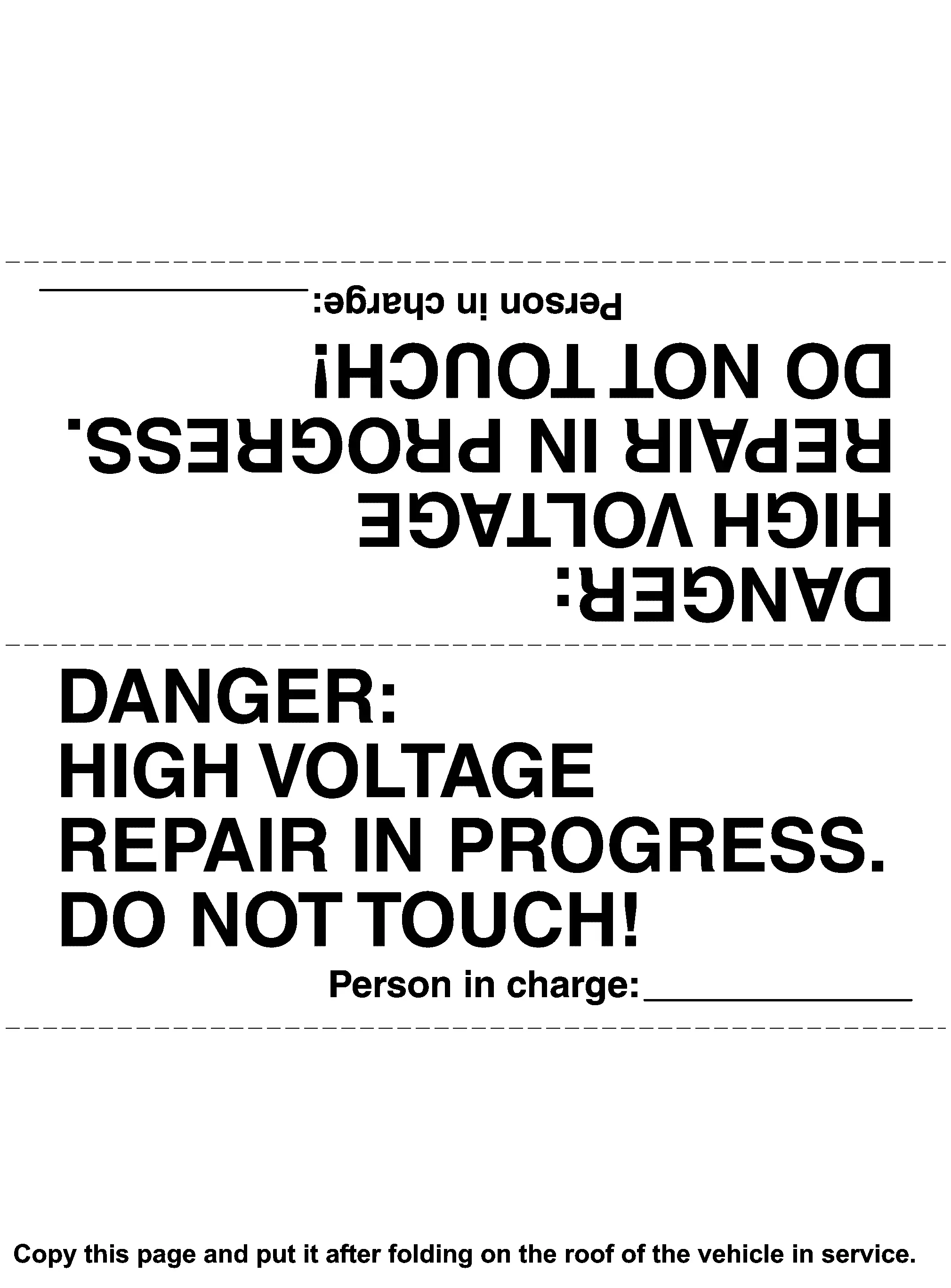
POST A SIGN OF “DANGER! HIGH VOLTAGE AREA. KEEP OUT”
Call the attention of other workers and indicate "High voltage work in progress." Do not touch vehicles where work is being performed on high voltage systems.
PRECAUTIONS FOR TECHNICIANS USING MEDICAL ELECTRIC : Precautions
OPERATION PROHIBITION
NORMAL CHARGE PRECAUTION
PRECAUTION AT TELEMATICS SYSTEM OPERATION
PRECAUTION AT INTELLIGENT KEY SYSTEM OPERATION
HOW TO DISCONNECT HIGH VOLTAGE : Precautions
PROCEDURE FOR DISCONNECTING HIGH VOLTAGE
Be sure to follow the procedure below and disconnect the high voltage before performing inspection or servicing of the high voltage system.
Turn power switch OFF.
Disconnect 12V battery negative terminal.
Remove service plug, following below procedure.
Open the zipper
 on the rear seat cushion.
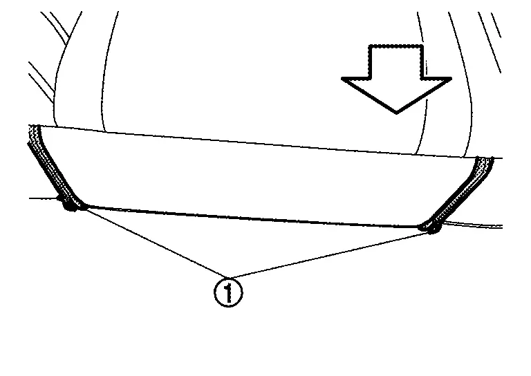

: Engine front Remove the service plug terminal cover mounting bolts
 and nuts
 , and remove the service plug terminal cover.

Remove service plug as per the following steps:


Push up lever until the stops.
Press pawl to unlock.
Push up lever.
Pull out service plug.
After removing the service plug, immediately wind the insulation tape around the terminal on the Li-ion battery side.
DANGER:Touching high voltage components without using the appropriate protective equipment will cause electrocution.Wait for a minimum of approximately 10 minutes after the service plug is removed.
PROCEDURE FOR CONNECTING HIGH VOLTAGE
Check that 12V battery negative terminal is disconnected.
Install service plug as per the following steps.
DANGER:Touching high voltage components without using the appropriate protective equipment will cause electrocution.
Install service plug.
Push down lever.
Press pawl to lock lever.
Check that lever is locked.
Connect 12V battery negative terminal.
CHECK VOLTAGE IN HIGH VOLTAGE CIRCUIT : Precautions
DANGER:Since hybrid vehicles and electric vehicles contain a high voltage battery, there is the risk of electric shock, electric leakage, or similar accidents if the high voltage component and Nissan Ariya vehicle are handled incorrectly. Be sure to follow the correct work procedures when performing inspection and maintenance.
INSPECTION
Remove the bus bar cover from high voltage junction box. Refer to HIGH VOLTAGE POWER DELIVERY ASSEMBLY : Removal & Installation.
Measure the voltage between the terminals of the bus bar.
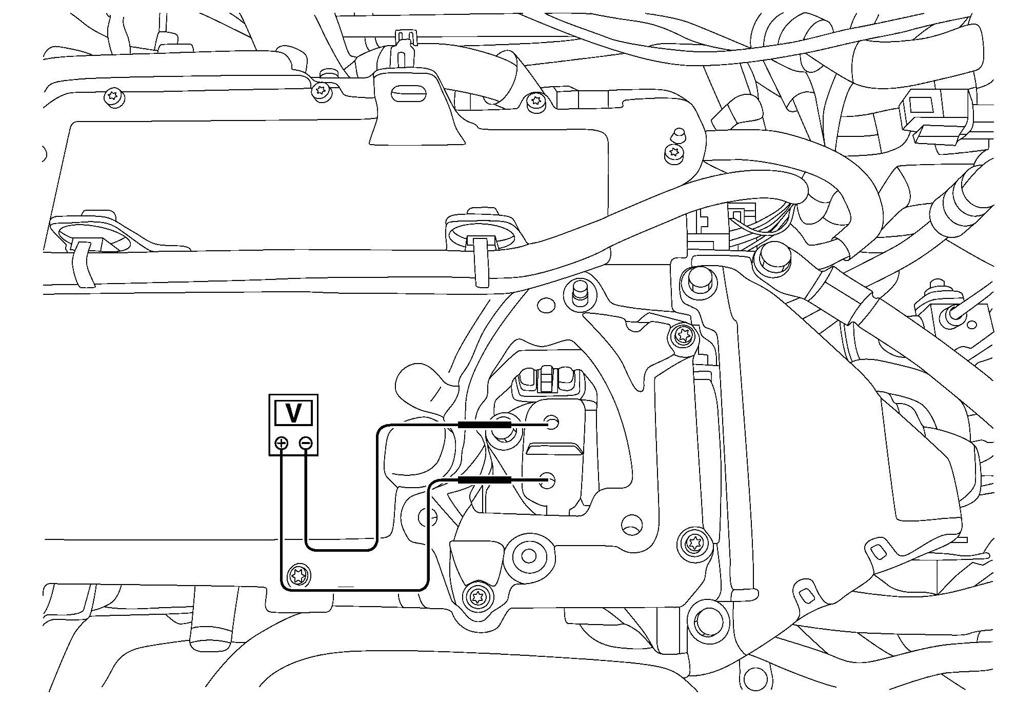
Standard : 5 V or less
HIGH VOLTAGE WARNING LABEL : Precautions
LOCATION TO APPLY HIGH VOLTAGE WARNING LABEL
2WD

| No. | Position to apply | Refer to |
|---|---|---|
|
Li-ion battery |
|
 |
High voltage harness (Rear) |
|
 |
Service plug |
|
 |
High voltage harness (Front) |
|
 |
PTC heater | High Voltage Warning Label |
 |
High voltage junction box | Component Description |
| On-board charger | ||
| DC/DC converter |
AWD
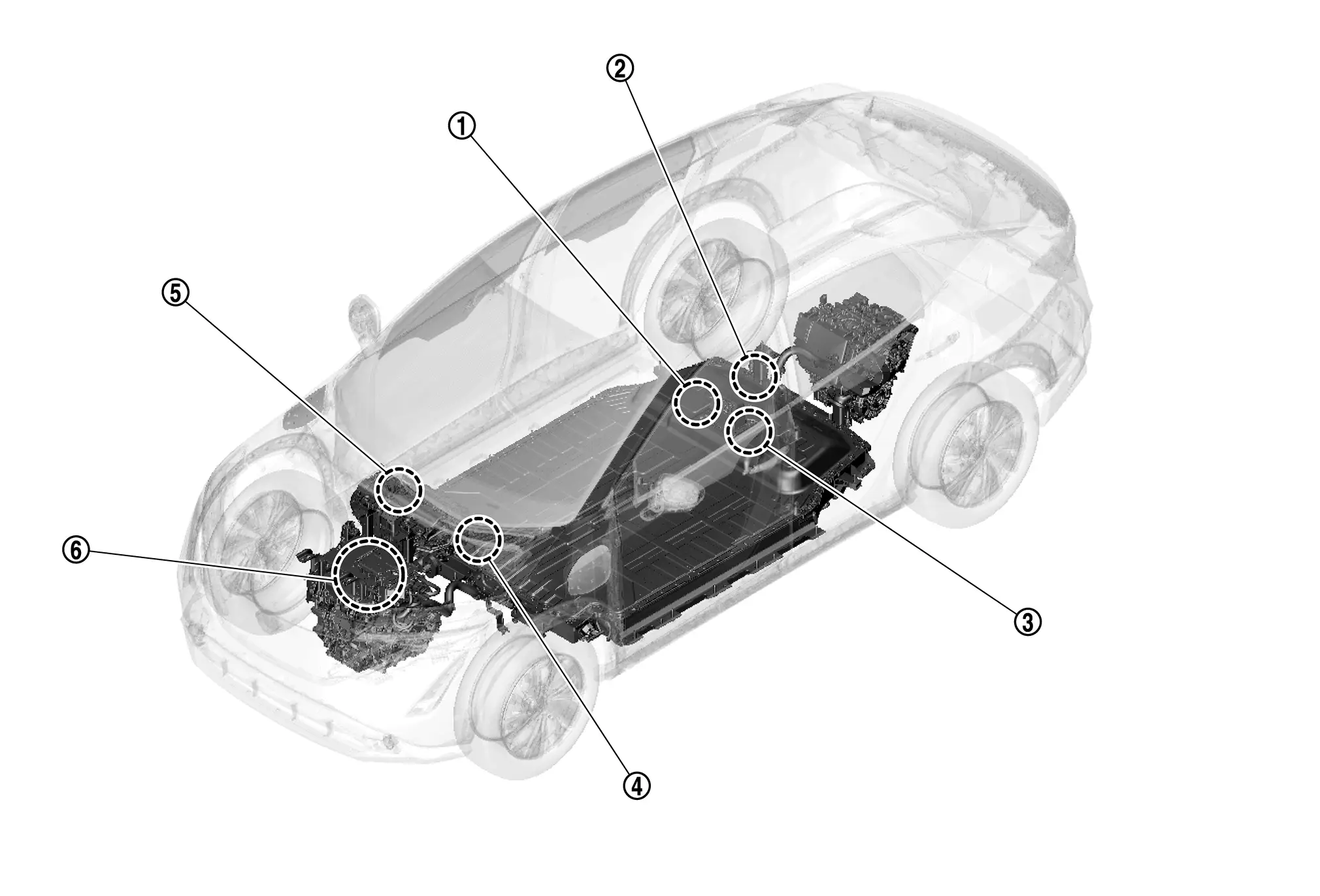
| No. | Position to apply | Refer to |
|---|---|---|
|
Li-ion battery |
|
|
High voltage harness (Rear) |
|
|
Service plug |
|
|
High voltage harness (Front) |
|
|
PTC heater | High Voltage Warning Label |
|
High voltage junction box | Component Description |
| On-board charger | ||
| DC/DC converter |
INSULATED PROTECTIVE WEAR AND INSULATING TOOLS : Precautions
PROTECTIVE WEAR CONTROL
Perform an inspection before beginning work, and do not use any items where abnormalities are found.
DAILY INSPECTION
This inspection is performed before and after use, the worker in responsible who will directly use the items inspects them and checks for deterioration and damage.
Insulated gloves
Inspect the insulated gloves for scratches, holes, and tears. (Visual check and air leakage test)
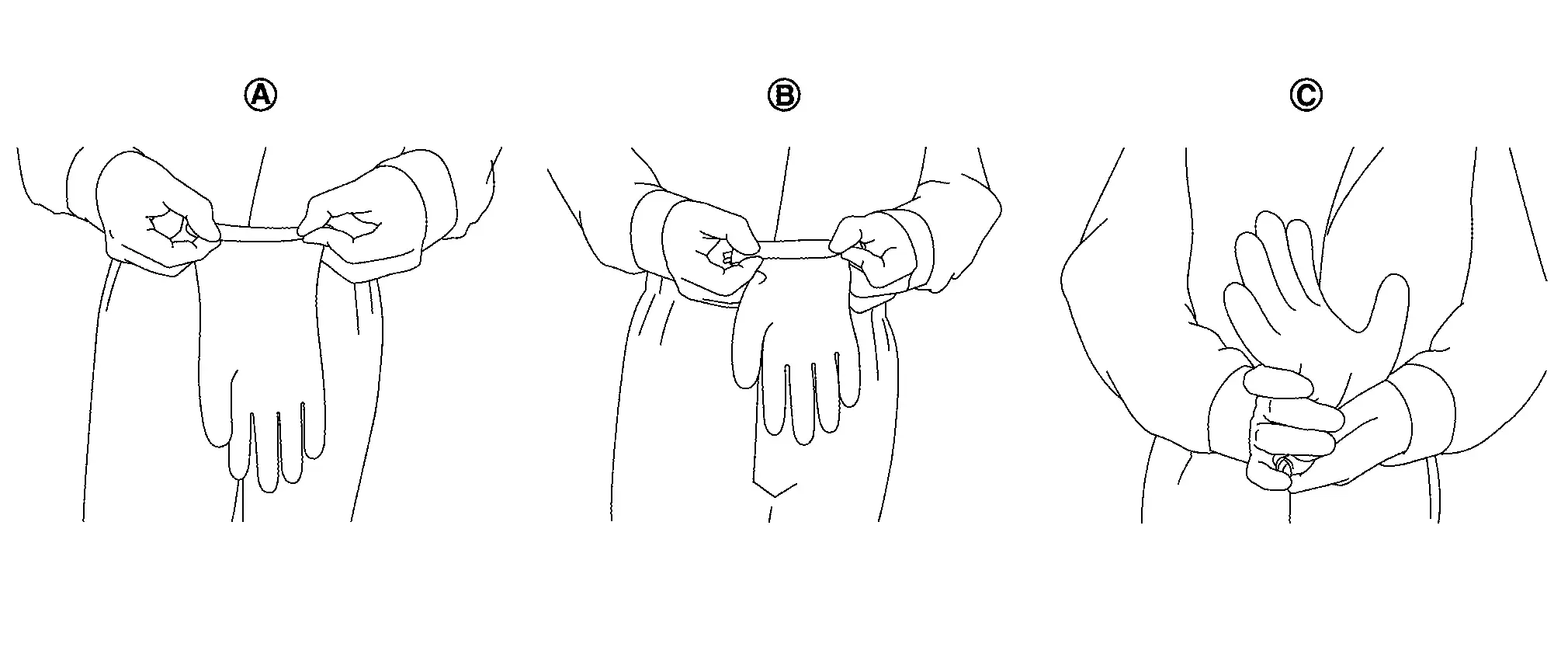
A : Hold glove and fold as shown in the figure. B : Fold three or four more times, preventing air from escaping from the glove. C : Squeeze glove to check that the glove has no holes. Insulated safety shoes
Inspect the insulated safety boots for holes, damage, nails, metal pieces, wear or other problems on the soles. (Visual check)
Insulated rubber sheet
Inspect the insulated rubber sheet for tears. (Visual inspection)
INSULATING TOOLS
When performing work at locations where high voltage is applied (such as terminals), use insulated tools.
HANDLING OF INSULATION RESISTANCE TESTER
CAUTIONS FOR SCRAPPING VEHICLES : Precautions
The Li-ion battery must be removed from the vehicle before the vehicle is scrapped.
HANDLING OF DAMAGED VEHICLES : Precautions
PREPARATION ITEMS
| Preparation items | Specification | Purpose | |
|---|---|---|---|
| PPE (Personal Protective Equipment) | Insulated gloves | Up to 1,000 V | To protect people from high voltage electrical shock. |
| Insulated safety shoes | — | ||
| Safety shield | — | ||
| Wrenches | Size: 10mm | To remove the service plug access cover bolts. To remove the 12V battery terminal bolt. |
|
Heat proof solvent resistant protection gloves Heat proof solvent resistant protection shoes |
Heat proof solvent resistant protection tools. | To utilize in the event of a Li-ion battery electrolytic solution leak. | |
| Absorbent pad | The same pad used for internal combustion engine fluids can be used. | To absorb any Li-ion battery electrolytic solution leakage. | |
| Extinguisher | Type ABC For electrical fires caused by the electrical harnesses and components, etc. and oil fires. |
To extinguish a fire. | |
| Insulated tape | Insulating | To cover the damaged harnesses to protect from and prevent electrical shock. Tape should cover all bare or damaged wire. | |
HOW TO HANDLE THE DAMAGED VEHICLES AT AN ACCIDENT SCENE
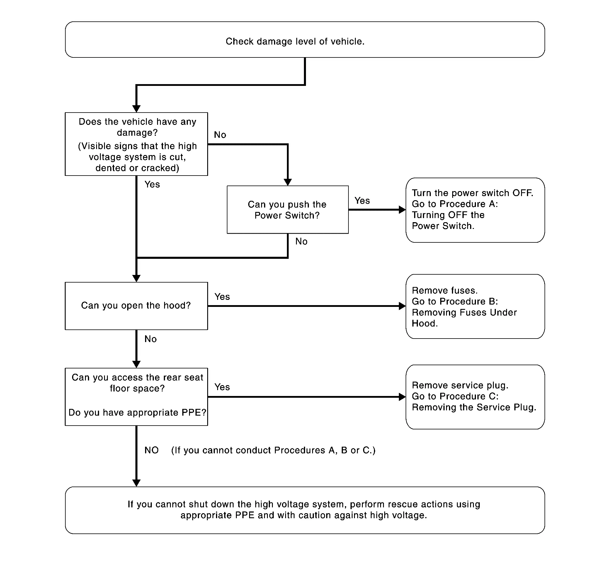
High voltage system shut-down procedure
Shut down the high voltage system according to vehicle damage level. Any of the following procedures can shut down the high voltage system. The first response operation should be done after shutting down the high voltage system.
If the vehicle is heavily damaged, for example the Li-ion battery is deformed, broken or cracked, appropriate PPE must be used and the Li-ion battery and high voltage components must not be touched.
DANGER:- Failure to properly shut down the high voltage system before the Emergency Response Procedures are performed may result in serious injury or death from electrical shock. To prevent from serious injury or death, DO NOT touch high voltage harnesses or components with bare hands.
- When contact with high voltage components or high voltage harnesses is unavoidable, or when there is risk of such contact, be sure to wear appropriate PPE.
Indications the high voltage system is ON
If the READY indicator is ON, the high voltage system is active.
If the charge indicator is ON, the high voltage system is active.
If the air conditioning remote timer indicator (located on the HVAC controller) is ON, the high voltage system is active.
If the remote controlled air conditioning system is active, push the power switch to the ON position. This will turn OFF the remote controlled air conditioning system.
Before disconnecting the 12V battery terminal, if necessary, set the parking brake, lower the windows, unlock the doors, and open the rear hatch as required. Once 12V battery is disconnected, power controls will not operate.
Procedure A: Turning OFF the Power Switch.
Check the READY indicator status. If it is ON, the high voltage system is active.
Press the power switch once to turn OFF the high voltage system. Then verify whether the READY indicator is OFF.
If possible, keep the Intelligent Key at least 5 meters (16 feet) away from the Nissan Ariya vehicle.
Open the hood.
Disconnect the negative 12V battery cable. Insulate the negative 12V battery cable terminal with insulated tape.
Wait 10 minutes for complete discharge of the high voltage condenser after the power switch has been turned OFF and the battery cable has been disconnected.
Perform the first response action.
Procedure B: Removing Fuses Under Hood
Open the hood.
Press and expand the pawls on the sides of the fuse box and remove the fuse box from its housing.
Remove the following fuses:
VCM IG fuse (F15 VCM IGN 10A)
PBW Fuse (F21 PBW IGN 15A)
VCM Fuse (F3 VCM 20A)
If you cannot identify the above fuses, remove all fuse in the fuse box.
Disconnect the negative 12V battery cable. Insulate the negative 12V battery cable terminal with insulated tape.
Wait 10 minutes for complete discharge of the high voltage condenser after the fuses and pulled and battery cable has been disconnected.
Perform the first response action.
Procedure C: Removing the Service Plug
DANGER:- Do not remove the service plug without wearing appropriate PPE to help protect the responder from any serious injury or death by electrical shock.
- Immediately cover the service plug socket with insulated tape. To avoid electric shock, DO NOT touch the terminals inside the socket.
Turn power switch OFF.
Disconnect 12V battery negative terminal.
Remove service plug, following below procedure.
Open the zipper
on the rear seat cushion.: Engine front Remove the service plug terminal cover mounting bolts
and nuts , and remove the service plug terminal cover.Remove service plug as per the following steps:
Push up lever until the stops.
Press pawl to unlock.
Push up lever.
Pull out service plug.
After removing the service plug, immediately wind the insulation tape around the terminal on the Li-ion battery side.
DANGER:Touching high voltage components without using the appropriate protective equipment will cause electrocution.Wait for a minimum of approximately 10 minutes after the service plug is removed.
VEHICLE FIRE
In case of vehicle fire, contact fire department immediately and extinguish the fire if possible. If you must walk away from the Nissan Ariya vehicle, notify an appropriate responder or a rescue person of the fact that the vehicle is an electric car and contains a high voltage system and warm all others.
LI-ION BATTERY DAMAGE AND FLUID LEAKS
Li-ion Battery Electrolyte Solution Characteristics:
Clear in color
Sweet odor
Similar viscosity to water
Skin irritant
Eye irritant - If contact with plenty of water and see a doctor immediately.
Highly flammable
Electrolyte liquid or fumes that have come into contact with water vapors in the air will create an oxidized substance. This substance may irritate skin and eyes. In these cases, rinse with plenty of water and see a doctor immediately.
Since the Li-ion battery is made up of many small sealed battery modules, electrolyte solution should not leak in large quantity.
HANDLING OF A VEHICLE WITH A DEAD BATTERY : Precautions
For the handling of a vehicle when the battery is dead, refer to Tow Truck Towing.
Procedure for Park Lock Release Nissan Ariya
Work Procedure
For maintaining N position status, perform the following work. If the Nissan Ariya vehicle is moved without performing the following work, serious accident may be caused.
But if not need unavoidably towing moved (if not emergency situation), Refer to Tow Truck Towing.
WORK PROCEDURE
12 V electric power is supplied with booster cable to the 12V battery.
Set the power switch to ON without depressing brake pedal.
Check that parking brake is activated. (Check that indicator lamp for parking brake is ON.)
Select N position.
Depress brake pedal and shift to “N” position. After maintaining this status some time, check that shift position indicator is indicated to “N” position.
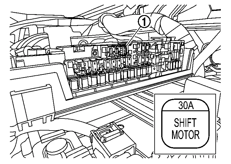
Open hood and remove fuse and fusible link block cover
.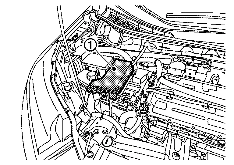
Remove 30A fuse (shown as SHIFT MOTOR)
.
Release parking brake.
Set the power switch to OFF.
Remove booster cable from 12V battery.
Move the Nissan Ariya vehicle while power switch is OFF.
PROCEDURE OF RECOVERY TO THE NORMAL STATE AFTER COMPLETION OF WORK
Disconnect the 12V battery cable from the negative terminal.
Install 30A fuse (shown as SHIFT MOTOR).
Install fuse and fusible link block cover.
Connect the 12V battery cable to the negative terminal.
Wait for 5 seconds after set the power switch to ON and then push P position switch.
Set the power switch to OFF and wait for 5 seconds.
Check "Self Diagnostic Result" of all ECUs and erase detected DTC.
Lifting Point Nissan Ariya
Commercial Service Tools
| Tool name | Description |
|---|---|
| Board on attachment |  |
| Safety stand attachment | 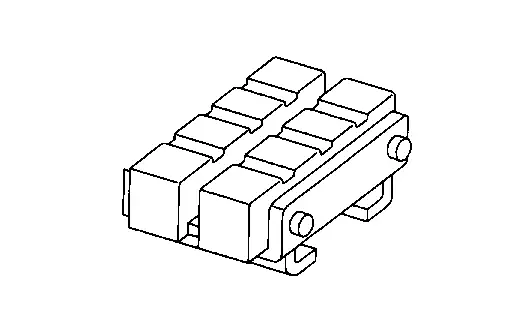 |
Garage Jack and Safety Stand and 2-Pole Lift
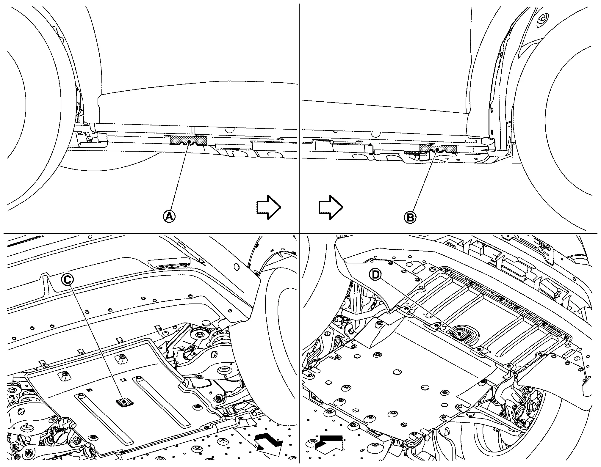
|
Safety stand point and lift up point (rear) | |
Safety stand point and lift up point (front) |  |
Garage jack point (rear) |
 |
Garage jack point (front) | ||||
|
: Nissan Ariya Vehicle front |
Board-On Lift
The board-on lift attachment (A) set at front end of Nissan Ariya vehicle should be set on the front of the sill under the front door opening.
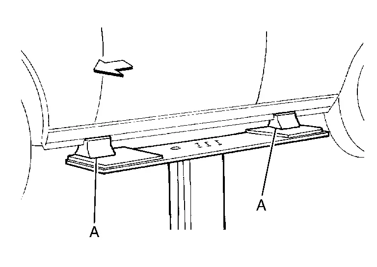
: Nissan Ariya Vehicle front Position attachments at front and rear ends of board-on lift.
Tow Truck Towing Nissan Ariya 2026
Tow Truck Towing
2WD MODELS
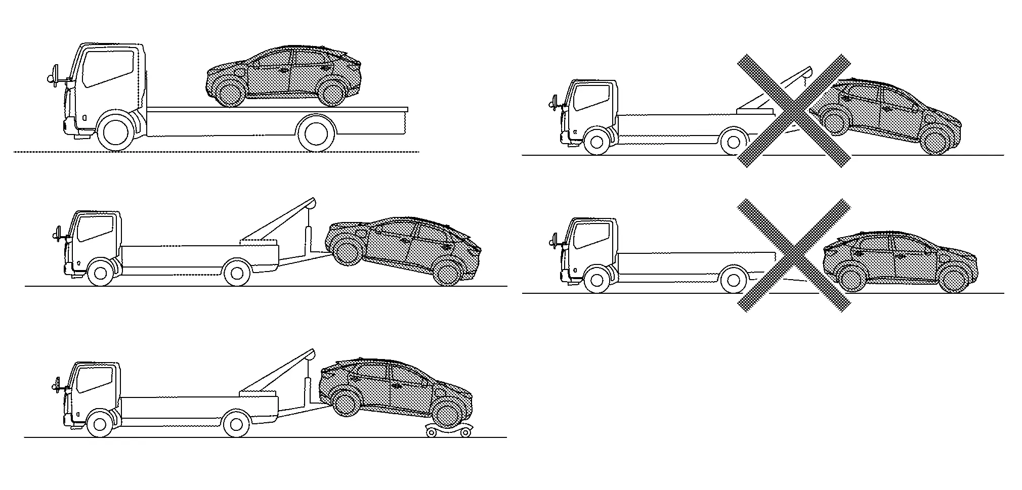
NISSAN recommends that the vehicle be towed with the driving (front) wheels off the ground or that the Nissan Ariya vehicle be placed on a flatbed truck as illustrated.
AWD MODELS

NISSAN recommends that a dolly used as illustration when towing AWD models.
Vehicle Recovery (Freeing a Stuck Vehicle)
FRONT
Remove the hook cover from the bumper using a remover tool.
Securely install the Nissan Ariya vehicle recovery hook stored.
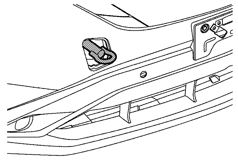
Check that the hook is properly secured in the stored place after use.