Description
- Component Parts
- Mechanical System. Electric Shift
- System
- Diagnosis System (electric Shift Control Module). Consult Function
Mechanical System. Electric Shift Nissan Ariya 2026
Structure and Operation
Parking Mechanism
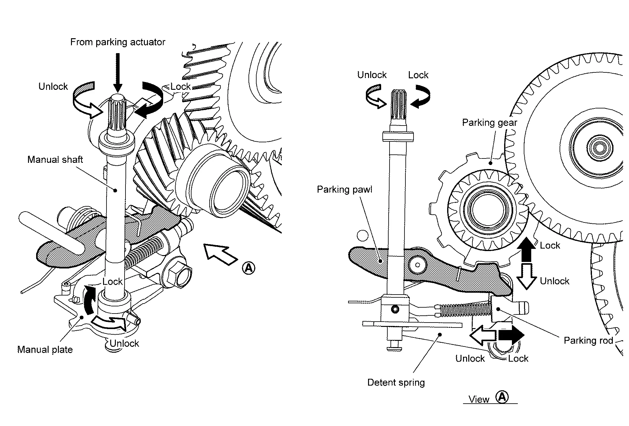
The parking mechanism is composed of the manual shaft, manual plate, detent spring, parking rod, parking pawl, and parking gear. It locks/unlocks the parking mechanism by operation of the parking actuator.
When the parking actuator operates by the signal from the electric shift control module, the manual shaft and the manual plate connected mechanically with the parking actuator rotates and the parking rod slides.
The parking pawl is pushed by sliding the parking rod and it meshes with the parking gear to lock the parking mechanism.
Diagnosis System (electric Shift Control Module). Consult Function Nissan Ariya first Gen
Diagnosis Description
APPLICATION ITEMS
CONSULT can display each diagnostic item using the diagnostic test modes as follows.
| Diagnostic test mode | Function |
|---|---|
| Self Diagnostic Result | Display DTC which electric shift control module memorizes. |
| Data Monitor | Input/Output data in the electric shift control module can be read. |
| Work support | This mode enable a technician to adjust some devices faster and more accurately by following the indication on the CONSULT. |
| ECU Identification | Part number of electric shift control module can be read. |
*: The following diagnosis information is erased by erasing.
DTC
Freeze frame data (FFD)
SELF DIAGNOSTIC RESULT
Refer to DTC Index.
When “Current DTC” is displayed on self-diagnosis result.
The system is presently malfunctioning.
When “Past DTC” is displayed on self-diagnosis result.
System malfunction in the past is detected, but the system is presently normal.
FREEZE FRAME DATA (FFD)
Records the following vehicle conditions when DTC is detected and displays them on CONSULT.
| Monitor item (Unit) | Remarks | |
|---|---|---|
| ODO/TRIP METER | (km or mile) | Displays the total mileage (odometer value) when the DTC was detected. |
| DTC count | (count) | Displays the DTC detection count. |
| System error type | Displays the malfunction type when a malfunction occurred in the system. Type 1: Shift input system error Type 2: Parking actuator system error Type 3: Internal error of electric shift control module Type 4: P position switch input error Type 5: Parking actuator heating protection state Type 6: ― Type 7: Error other than types 1 - 5 |
|
| Ignition power supply | Displays the power supply state based on the power switch ON signal. | |
| GADE | Displayed but not used. | |
| Power supply voltage | (V) | Displays the 12V power supply voltage that is input into the electric shift control module. |
| Travel distance | (km or mile) | Displays the total mileage (odometer value) when the DTC was detected. |
| Target shift position | Displays the target shift position which is recognized by the electric shift control module. | |
| Actual shift position | Displays the shift position which is recognized by the electric shift control module. | |
| Parking actuator relay | Displays the instruction state sent from the electric shift control module to the parking actuator relay. | |
| Park lock state | Displays the status of the parking mechanism. | |
| Ignition signal | Displays the input status of the power switch signal. | |
| ECU control mode | Displays the system control status that was judged by the electric shift control module. | |
| Motor drive mode 1 | Displays the motor driving status of the parking actuator (when normal). | |
| CPU reset | Displays whether or not the data inside the electric shift control module is reset when shift change occurs. | |
| Motor drive mode 2 | Displays the motor driving status of the parking actuator (when encoder provisional error was detected). | |
| U voltage | (V) | Displays the A/D conversion value for the motor U-phase terminal voltage. |
| V voltage | (V) | Displays the A/D conversion value for the motor V-phase terminal voltage. |
| W voltage | (V) | Displays the A/D conversion value for the motor W-phase terminal voltage. |
| Power supply voltage (after filter) | (V) | Monitors the main power voltage value of the electric shift control module and displays the monitor value. |
| Motor control mode | Displays the motor control state inside the parking actuator. | |
| Target park lock/unlock counter value | (count) | Displays the target count value of the parking actuator. |
| Current park lock/unlock counter value | (count) | Displays the encoder count value after parking actuator activation. |
| Current monitor | (A) | Displays the parking actuator electrical current value during wall contact control. |
| Current monitor (resistor diagnosis) | (A) | Displays the parking actuator electrical current value when diagnosis of the current detection circuit is performed. |
| Encoder temporary error flag | Displays the encoder provisional error status inside the parking actuator. | |
| Record counter | (count) | Displays the malfunction detection count. |
DATA MONITOR
| Monitor item (Unit) | Remarks | |
|---|---|---|
| Lever position 1 | Displays that the selector lever is in the R position. | |
| Lever position 2 | Displays that the selector lever is in the Nr position. | |
| Lever position 3 | Displays that the selector lever is in the H position. | |
| Lever position 4 | Displays that the selector lever is in the Nd position. | |
| Lever position 5 | Displays that the selector lever is in the D/B position. | |
| P position 1 | Displays the operating status of the P position switch. | |
| System error type | Displays the malfunction type when a malfunction occurred in the system. Type 1: Shift input system error Type 2: Parking actuator system error Type 3: Internal error of electric shift control module Type 4: P position switch input error Type 5: Parking actuator heating protection state Type 6: ― Type 7: Error other than types 1 - 5 |
|
| Ignition power supply | Displays the power supply state based on the power switch ON signal. | |
| GADE | Displayed but not used. | |
| Power supply voltage | (V) | Displays the 12V power supply voltage that is input into the electric shift control module. |
| Travel distance | (km or mile) | Displays the total mileage (odometer value). |
| Target shift position | Displays the target shift position which is recognized by the electric shift control module. | |
| Actual shift position | Displays the shift position which is recognized by the electric shift control module. | |
| Parking actuator relay | Displays the instruction state sent from the electric shift control module to the parking actuator relay. | |
| Park lock state | Displays the status of the parking mechanism. | |
| Shift sensor 1 | Displays the signal status of the electric shift sensor No.1. | |
| Shift sensor 2 | Displays the signal status of the electric shift sensor No.2. | |
| Shift sensor 3 | Displays the signal status of the electric shift sensor No.3. | |
| Shift sensor 4 | Displays the signal status of the electric shift sensor No.4. | |
| Shift sensor 5 | Displays the signal status of the electric shift sensor No.5. | |
| Shift sensor 6 | Displays the signal status of the electric shift sensor No.6. | |
| Shift sensor 7 | Displays the signal status of the electric shift sensor No.7. | |
| Shift sensor 8 | Displays the signal status of the electric shift sensor No.8. | |
| P position switch signal | Displays the signal status of P position switch No.1 and No.2. | |
| Ignition signal | Displays the input status of the power switch signal. | |
| Range shift inhibit | Displays the status of shift operation inhibition due to low voltage. | |
| Shifter error status | Display the malfunction status of the electric shift sensors. | |
| ECU control mode | Displays the system control status that was judged by the electric shift control module. | |
| Motor control stop request | Displays the motor control stop request inside the parking actuator. | |
| Open control request | Displays the motor activation request when an encoder provisional error is detected. | |
| Parking actuator relay OFF request | Displays the OFF request status for the parking actuator relay. | |
| Shift sensor 1 voltage | (V) | Displays the voltage value of electric shift sensor No.1. |
| Shift sensor 2 voltage | (V) | Displays the voltage value of electric shift sensor No.2. |
| Shift sensor 3 voltage | (V) | Displays the voltage value of electric shift sensor No.3. |
| Shift sensor 4 voltage | (V) | Displays the voltage value of electric shift sensor No.4. |
| Shift sensor 5 voltage | (V) | Displays the voltage value of electric shift sensor No.5. |
| Shift sensor 6 voltage | (V) | Displays the voltage value of electric shift sensor No.6. |
| Shift sensor 7 voltage | (V) | Displays the voltage value of electric shift sensor No.7. |
| Shift sensor 8 voltage | (V) | Displays the voltage value of electric shift sensor No.8. |
| P position switch 1 voltage | (V) | Displays the voltage value of P position switch No.1. |
| P position switch 2 voltage | (V) | Displays the voltage value of P position switch No.2. |
| Motor drive mode 1 | Displays the motor driving status of the parking actuator (when normal). | |
| Parking actuator working refusal | Displays the operation rejection status for the parking actuator. | |
| CPU reset | Displays whether or not the data inside the electric shift control module is reset when shift change occurs. | |
| Motor drive mode 2 | Displays the motor driving status of the parking actuator (when encoder provisional error was detected). | |
| U voltage | (V) | Displays the A/D conversion value for the motor U-phase terminal voltage. |
| V voltage | (V) | Displays the A/D conversion value for the motor V-phase terminal voltage. |
| W voltage | (V) | Displays the A/D conversion value for the motor W-phase terminal voltage. |
| Power supply voltage (after filter) | (V) | Monitors the main power voltage value of the electric shift control module and displays the monitor value. |
| Motor control mode | Displays the motor control state inside the parking actuator. | |
| Current monitor | (A) | Displays the parking actuator electrical current value during wall contact control. |
| Current monitor (resistor diagnosis) | (A) | Displays the parking actuator electrical current value when diagnosis of the current detection circuit is performed. |
| Encoder temporary error flag | Displays the encoder provisional error status inside the parking actuator. | |
WORK SUPPORT
| Item | Usage |
|---|---|
| ACTUATOR LERNING VALUE ELIMINATION | Erases the learned parking actuator P position. |
ECU IDENTIFICATION
Part number of electric shift control module can be read.