Ev Control System

In this manual: Ev Control System
How to Use This Manual — 1Precautions — 1Preparation — 1Vehicle Information — 1Basic Inspection — 1Preparation. Commercial Service Tools Or/and Repair Part — 1Description — 1Component Parts — 1System — 1Diagnosis System (vcm) — 1Ecu Diagnosis Information. Vcm — 1Ev Control System — 1Ev/hev (vcm) — 1Component Parts /circuit Diagnosis — 1Ev Control System — 1Periodic Maintenance. Ev System Warning Lamp — 1Removal and Installation. Vcm — 1Traction Motor System :: Front Traction Motor — 1Preparation — 1Description — 4Basic Inspection — 2Dtc Diagnosis — 2Component Parts /circuit Diagnosis — 1Traction Motor System :: Rear Traction Motor — 1Description — 4Basic Inspection — 2Dtc Diagnosis — 2Component Parts /circuit Diagnosis — 1Removal and Installation — 1Ev Battery System :: 66kwh Li-Ion Battery — 1Description — 4Basic Inspection — 2Dtc Diagnosis — 2Component Parts /circuit Diagnosis — 1Removal and Installation — 1Disassembly and Assembly — 2Service Data — 1Ev Battery System :: 91kwh Li-Ion Battery — 1Description — 4Basic Inspection — 2Dtc Diagnosis — 2Component Parts /circuit Diagnosis — 1Removal and Installation — 1Disassembly and Assembly — 1Service Data — 2Preparation. Vehicle Charging System — 1Vehicle Charging System :: Description — 1Component Parts — 2System — 1Diagnosis System (on-Board Charger) — 1Diagnosis System (dc/dc Converter) — 1Ecu Diagnosis Information — 1Vehicle Charging System — 1Charger/pd Module (on-Board Charger) — 1Cplc (cplc) — 1Dcdc (dc/dc Converter) — 1Component Parts/circuit Diagnosis — 1Symptom Diagnosis — 1Evse Inspection — 1Periodic Maintenance — 1Removal and Installation — 1Disassembly and Assembly — 1Preparation. High Voltage Cooling System — 1Description — 1Symptom Diagnosis. Overheating Cause Analysis — 1Periodic Maintenance — 1Coolant — 1Removal and Installation — 1Radiator — 1Service Data — 1Removal and Installation. Accelerator Control System — 1Reduction Gear: Re1f62a — 1Removal and Installation — 1Transaxle & Transmission :: Electric Shift — 1Description — 3Basic Inspection — 2Dtc Diagnosis — 2Component Parts /circuit Diagnosis — 1Removal and Installation — 1Rear Final Drive: Rn1r62a — 1Removal and Installation — 1Preparation. Front Axle System — 1Symptom Diagnosis. Noise, Vibration and Harshness (nvh) Troubleshooting — 1Periodic Maintenance — 1Removal and Installation — 1Service Data. Front Drive Shaft — 12wd — 14wd — 1Periodic Maintenance — 1Removal and Installation — 1Preparation. Front Suspension System — 1Symptom Diagnosis. Noise, Vibration and Harshness (nvh) Troubleshooting — 1Periodic Maintenance — 1Removal and Installation — 1Service Data — 1Symptom Diagnosis. Noise, Vibration and Harshness (nvh) Troubleshooting — 1Periodic Maintenance — 1Removal and Installation — 1Service Data — 1Preparation. Road Wheels & Tires System — 1Description — 1System — 1Ecu Diagnosis Information. Bcm (body Control Module) — 1Tpms — 1Dtc/circuit Diagnosis — 1Symptom Diagnosis — 1Periodic Maintenance. Road Wheels & Tires — 1Removal and Installation — 1Service Data — 1Preparation. Brake System — 1System Description — 1Component Parts — 1Ecu Diagnosis Information. Electrically-Driven Intelligent Brake Unit — 1Basic Inspection — 1Dtc/circuit Diagnosis — 1Symptom Diagnosis — 1Periodic Maintenance — 1Removal and Installation — 1Service Data — 1Preparation. Parking Brake System — 1System Description — 1Component Parts — 1System — 1Ecu Diagnosis Information. Abs Actuator and Electric Unit (control Unit) — 1Basic Inspection. Diagnosis and Repair Work Flow — 1Component Parts /circuit Diagnosis — 1Symptom Diagnosis — 1Removal and Installation — 1Brake Control System :: With Vdc — 1System Description — 3Basic Inspection — 2Dtc/circuit Diagnosis — 1Symptom Diagnosis — 2Removal and Installation — 1Brake Control System :: Automatic Brake Hold — 1System Description — 3Component Parts /circuit Diagnosis — 1Removal and Installation — 1Brake Control System :: E-Step — 1System Description — 3Removal and Installation — 1System Description — 1Ecu Diagnosis Information — 1Basic Inspection — 1Symptom Diagnosis — 1Rear Automatic Braking — 1System Description — 1Basic Inspection — 1Preparation. Steering System — 1System Description — 1Component Parts — 1Basic Inspection — 1Dtc/circuit Diagnosis — 1Symptom Diagnosis — 1Periodic Maintenance. Steering Wheel — 1Removal and Installation — 1Service Data — 1System Description — 1Component Parts — 1Steering Control System — 1Ecu Diagnosis Information. Power Steering Control Module — 1Dtc/circuit Diagnosis — 1Component Parts /circuit Diagnosis — 1Symptom Diagnosis — 1Removal and Installation. Power Steering Control Module — 1System Description — 1Removal and Installation — 1System Description — 1System — 1Basic Inspection. Diagnosis and Repair Work Flow — 1Dtc/circuit Diagnosis — 1Symptom Diagnosis — 1Component Parts — 1Basic Inspection — 1Removal and Installation — 1System Description — 1System — 1Ecu Diagnosis Information. Air Bag Diagnosis Sensor Unit — 1Basic Inspection — 1Dtc/circuit Diagnosis — 1Symptom Diagnosis — 1System Description. Description. Ventilation System — 1Removal and Installation — 1Preparation. Preparation — 1System Description — 1Basic Inspection — 1Symptom Diagnosis — 1Removal and Installation — 1Electric Compressor — 1Cooler Pipe and Hose — 1A/c Unit Assembly Cover — 1A/c Unit Assembly — 1Heater & Air Conditioning Control System :: Automatic Air Conditioning — 1System Description — 1Ecu Diagnosis Information — 1Basic Inspection — 2Dtc Diagnosis — 1Symptom Diagnosis — 1Removal and Installation — 2Preparation. Preparation — 1Symptom Diagnosis. Squeak and Rattle Trouble Diagnoses — 1Removal and Installation — 1Preparation. Instrument Panel — 1Component Parts — 1System — 1Ecu Diagnosis Information. Flexible Center Storage Control Module — 1Basic Inspection. Diagnosis and Repair Work Flow — 1Dtc/circuit Diagnosis — 1Symptom Diagnosis — 1Removal and Installation — 1Preparation. Preparation — 1Component Parts — 1System — 1Ecu Diagnosis Information. Driver Lumbar Support Control Module — 1Basic Inspection. Diagnosis and Repair Work Flow — 1Dtc/circuit Diagnosis — 1Symptom Diagnosis — 1Removal and Installation — 1System Description — 1System — 1Ecu Diagnosis Information — 1Basic Inspection — 1Dtc/circuit Diagnosis — 1Symptom Diagnosis — 1Manual Function Does Not Operate — 1Memory Function Does Not Operate — 1Removal and Installation — 1Preparation. Preparation — 1System Description — 1System (intelligent Key System) — 1Diagnosis System (bcm) — 1Ecu Diagnosis Information — 1Basic Inspection — 1Dtc/circuit Diagnosis — 1U2141-87 Can Comm Circuit — 1Power Supply and Ground Circuit — 1Symptom Diagnosis — 1Automatic Back Door Operation Does Not Operate — 1Back Door Does Not Open — 1Door Does Not Lock/unlock with Door Lock and Unlock Switch — 1Removal and Installation — 1Hood — 1Radiator Core Support — 1Charge Port Lid — 1Front Fender — 1Front Door — 1Rear Door — 1Back Door — 1Hood Lock — 1Front Door Lock — 1Rear Door Lock — 1Back Door Lock — 1Outside Key Antenna — 1System Description — 1System — 1Ecu Diagnosis Information. Inverter (front), Inverter (rear), Bcm, Intelligent Key Unit — 1Basic Inspection — 1Dtc/circuit Diagnosis — 1Symptom Diagnosis — 1Preparation — 1Symptom Diagnosis. Squeak and Rattle Trouble Diagnoses — 1Removal and Installation — 1System Description — 1Ecu Diagnosis Information — 1Basic Inspection — 1Dtc/circuit Diagnosis — 1Power Supply and Ground Circuit — 1Symptom Diagnosis — 1Front Passenger Side Power Window Does Not Operate — 1Rear Lh Side Power Window Does Not Operate — 1Rear Rh Side Power Window Does Not Operate — 1Removal and Installation. Power Window Main Switch — 1Preparation. Preparation — 1System Description — 1Ecu Diagnosis Information — 1Basic Inspection — 1Dtc/circuit Diagnosis — 1Power Supply and Ground Circuit — 1Sunroof Switch Assembly — 1Symptom Diagnosis — 1Auto Operation Does Not Operate — 1Removal and Installation — 1Preparation — 1Description — 1Symptom Diagnosis. Squeak and Rattle Trouble Diagnoses — 1Removal and Installation — 1Service Information — 6Repair Information — 1Precaution — 1Preparation — 1Removal and Installation — 1Service Data — 1Preparation. Preparation — 1Component Parts — 1System — 1Ecu Diagnosis Information — 1Wiring Diagram. Door Mirror — 1Basic Inspection. Diagnosis and Repair Work Flow — 1Dtc/circuit Diagnosis — 1Power Supply and Ground Circuit — 1Symptom Diagnosis — 1Removal and Installation — 1Exterior Lighting System :: Led Headlamp — 1System Description — 3Basic Inspection — 1Dtc/circuit Diagnosis — 1Symptom Diagnosis — 1Periodic Maintenance — 1Removal and Installation — 1System Description — 1System — 1Diagnosis System (bcm) — 1Ecu Diagnosis Information. Bcm, Intelligent Key Unit — 1Basic Inspection. Diagnosis and Repair Work Flow — 1Dtc/circuit Diagnosis — 1Symptom Diagnosis. Interior Lighting System Symptom — 1Removal and Installation — 1Service Data. Bulb Specifications — 1System Description — 1System — 1Ecu Diagnosis Information. Bcm, Ipdm E/r — 1Basic Inspection. Diagnosis and Repair Work Flow — 1Dtc/circuit Diagnosis — 1Symptom Diagnosis — 1Removal and Installation — 1System Description — 1Ecu Diagnosis Information. Bcm — 1Basic Inspection. Diagnosis and Repair Work Flow — 1Dtc/circuit Diagnosis — 1Symptom Diagnosis — 1Removal and Installation — 1Preparation. Preparation — 1Removal and Installation. Horn — 1Preparation. Commercial Service Tools Or/and Repair Part — 1System Description — 1Component Parts — 1Ecu Diagnosis Information. Approaching Vehicle Sound for Pedestrians (vsp) Control Unit — 1Approaching Vehicle Sound for Pedestrians (vsp) — 1Vsp [approaching Vehicle Sound for Pedestrians (vsp) Control Unit] — 1Approaching Vehicle Sound for Pedestrians (vsp) System — 1Removal and Installation — 1Removal and Installation — 1Wireless Charger — 1System Description — 1Basic Inspection — 1Dtc/circuit Diagnosis — 1Removal and Installation — 1Component Parts — 1System — 1Diagnosis System (bcm) — 1Ecu Diagnosis Information. Bcm — 1Basic Inspection — 1Dtc/circuit Diagnosis — 1Symptom Diagnosis — 1Removal and Installation — 1Can Fundamental — 1Description — 1Trouble Diagnosis — 1Can (controller Area Network) — 1Description — 1
20steps
~120min
5/5difficulty
Done 0 of 20
  • Diagnosis and Repair Work Flow
  • Additional Service When Replacing Vcm
  • Accelerator Pedal Released Position Learning
  • Mac Key Writing
  • Write Vehicle Identification Number Data

Diagnosis and Repair Work Flow Nissan Ariya 2026

Work Flow

BASIC INSPECTION FLOW
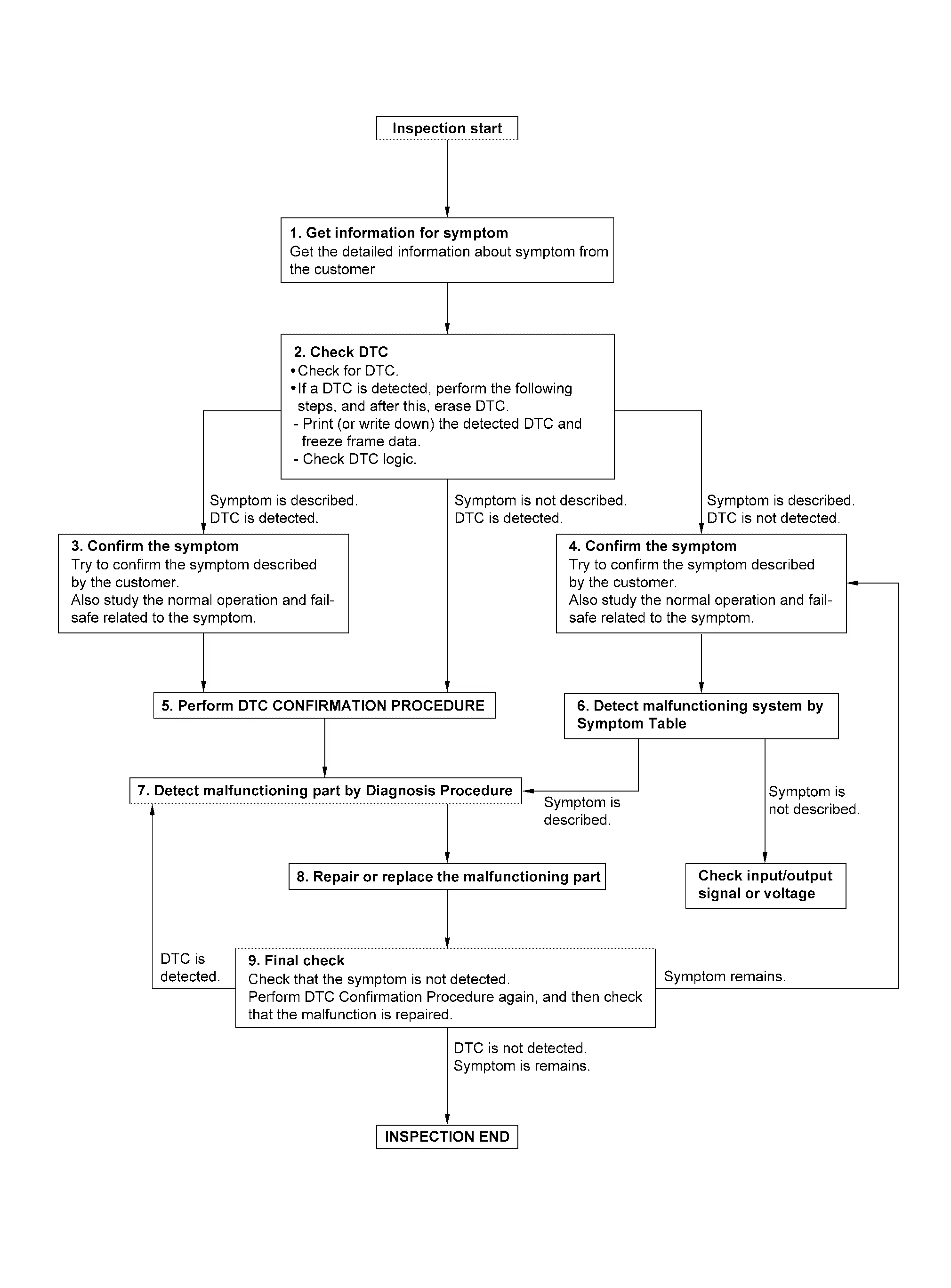
BASIC INSPECTION FLOW DETAIL

GET INFORMATION OF SYMPTOM

When vehicle is taken into the workshop with malfunction, try to get detailed information from the customer about the symptom (the condition and the environment when the incident/malfunction occurred) using the “Diagnostic Work Sheet”. Refer to Diagnostic Work Sheet.

>>

GO TO 2.

CHECK DTC

  1. Check DTC.

  2. If a DTC is detected, perform the following steps, and after this, erase DTC.

    • Print (or write down) the detected DTC and freeze frame data.

    • Check DTC logic. Refer to DTC Index.

    • Study the relationship between the cause detected by DTC and the symptom described by the customer. (Symptom Diagnosis is useful. Refer to Symptom Table.)

Are any symptoms described and any DTCs detected?

Symptom is described, DTC is detected>>

GO TO 3.

Symptom is described, DTC is not detected>>

GO TO 4.

Symptom is not described, DTC is detected>>

GO TO 5.

CONFIRM THE SYMPTOM

Try to confirm the symptom described by the customer.

Also study the normal operation and fail-safe related to the symptom. Refer to Fail-safe.

Diagnosis Work Sheet is useful to verify the incident.

Verify relation between the symptom and the condition when the symptom is occurred.

>>

GO TO 5 .

CONFIRM THE SYMPTOM

Try to confirm the symptom described by the customer.

Also study the normal operation and fail-safe related to the symptom. Refer to Fail-safe.

Diagnosis Work Sheet is useful to verify the incident.

Verify relation between the symptom and the condition when the symptom is occurred.

>>

GO TO 6.

PERFORM "DTC CONFIRMATION PROCEDURE"

Perform "DTC CONFIRMATION PROCEDURE" for the displayed DTC, and then check that DTC is detected again.

If two or more DTCs are detected, Refer to DTC Inspection Priority Chart. and determine trouble diagnosis order.

Is DTC detected?

YES>>

GO TO 7.

NO>>

Refer to Intermittent Incident.

DETECT MALFUNCTIONING SYSTEM BY "SYMPTOM TABLE"

Based on the confirmed symptom verification result in step 4, identify the place to start the trouble diagnosis based on the possible causes and symptom. Refer to Symptom Table.

Is a malfunctioning part detected?

YES>>

GO TO 7.

NO>>

Monitor input data from related sensors or check voltage of related VCM terminals using CONSULT. Refer to Physical Values.

DETECT MALFUNCTIONING PART BY DIAGNOSIS PROCEDURE

Inspect according to Diagnosis Procedure of the system.

Is a malfunctioning part detected?

YES>>

GO TO 8.

NO>>

Refer to Intermittent Incident.

REPAIR OR REPLACE THE MALFUNCTIONING PART

  1. Repair or replace the malfunctioning part.

  2. Reconnect parts or connectors disconnected during Diagnosis Procedure again after repair and replacement.

  3. Check DTC. If DTC is displayed, erase it. Refer to Diagnosis Description.

>>

GO TO 9.

FINAL CHECK

Perform DTC CONFIRMATION PROCEDURE or DTC Component Function Check again, and then check that the malfunction have been completely repaired. When symptom was described from the customer, refer to confirmed symptom in step 4 or 5, and check that the symptom is not detected.

Is DTC detected and does symptom remain?

YES-1>>

(DTC is detected): GO TO 7.

YES-2>>

(Symptom remains): GO TO 4.

NO>>

Before delivery the Nissan Ariya vehicle to the customer, always erase DTC.

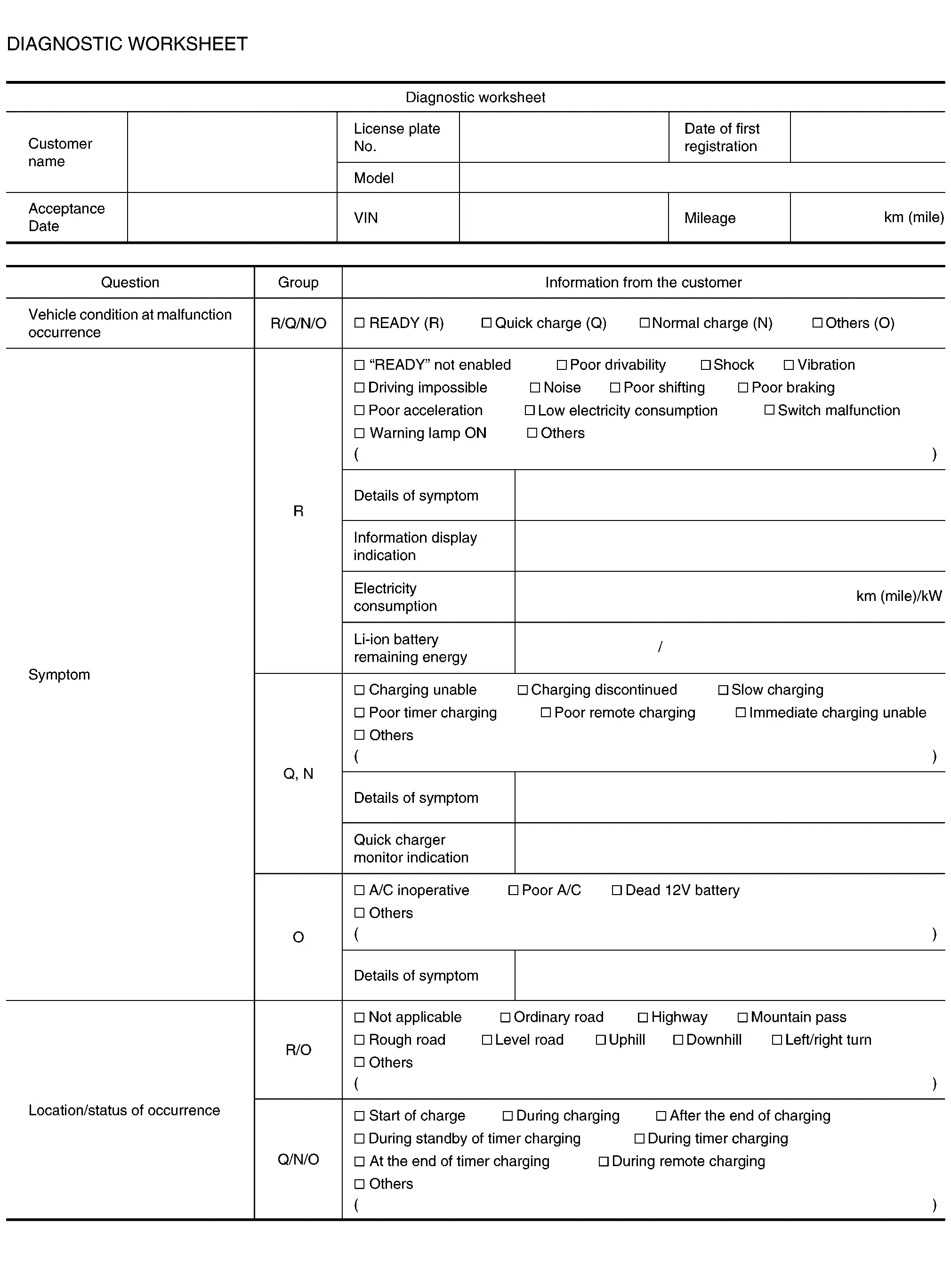
Diagnostic Work Sheet

DESCRIPTION

There are many operating conditions that lead to the malfunction of EV control system. A good grasp of such conditions can make troubleshooting faster and more accurate.

KEY POINT
WHAT Nissan Ariya Vehicle and parts
WHEN Date, Frequencies
WHERE Road conditions
HOW Operating conditions, Weather conditions, Symptoms

In general, each customer feels differently about symptoms. It is important to fully understand the symptoms or conditions for a customer complaint.

Utilize a diagnostic worksheet like the WORKSHEET SAMPLE below in order to organize all the information for troubleshooting.

Diagnostic Work Sheet
Additional Service When Replacing Vcm Nissan Ariya

Description

Vehicle specification needs to be written with CONSULT because it is not written after replacing the VCM.

CONSULT connects to network and then it downloads the configuration data from the server. Then CONSULT writes the Nissan Ariya vehicle specification to the VCM.

When replacing VCM, the following procedure must be performed.

  • Replace ECU

  • Write VIN data

  • MAC key writing

  • Accelerator pedal released position learning

Work Procedure

WRITING VEHICLE SPECIFICATION

With CONSULT

Perform writing Nissan Ariya vehicle specification to VCM according to "Replace ECU" in CONSULT Operation Manual.

>>

GO TO 2 .

WRITE VIN DATA

Refer to Work Procedure.

>>

GO TO 3.

WRITE MAC KEY

Refer to Work Procedure.

>>

GO TO 4.

LEARN ACCELERATOR PEDAL RELEASED POSITION

Refer to Work Procedure.

>>

GO TO 5.

CHECK DTC

  1. Turn OFF high voltage system by pushing power switch for two seconds or longer, and check that charge indicator is turned OFF.

  2. After turning OFF the high voltage system, open driver's door, get out Nissan Ariya vehicle, close driver's door, and wait for 5 minutes or more.

  3. Power switch ON

  4. Check DTC. If DTC in not detected, erase DTC.

>>

END

Accelerator Pedal Released Position Learning Nissan Ariya 1st generation

Description

Accelerator Pedal Fully Closed Position Learning is a function of VCM to learn the fully released position of the accelerator pedal by monitoring the accelerator pedal position sensor output signal. This work must be performed each time the harness connector of the accelerator pedal position sensor or VCM harness connector is disconnected. (For details, refer to Work Procedure.)

Work Procedure

ACCELERATOR PEDAL FULLY CLOSED POSITION LEARNING

  1. Check that accelerator pedal is fully closed position.

  2. Wait for 10 seconds or longer after power switch is ON.

  3. Turn OFF high voltage system by pushing power switch for two seconds or longer, and check that charge indicator is turned OFF.

  4. Repeat step 2 and step 3 four times.

  5. After turning OFF the high voltage system, open driver's door, get out Nissan Ariya vehicle, close driver's door, and wait for 5 minutes or more.

    If operating the vehicle, wait for least 5 minutes from that point.

>>

END

Mac Key Writing Nissan Ariya 1st generation

Description

When replacing VCM, it is necessary to write MAC key to VCM. Write MAC key to VCM according to "MAC Key writing" procedure of "CONSULT Operation Manual".

  • Power switch ON

  • CONSULT is connected to internet

Work Procedure

PERFORM MAC KEY WRITING

  1. Power switch ON.

  2. Select "MAC Key writing" on "Work Support" of "VCM" using CONSULT.

  3. Touch "Write".

>>

WORK END

Write Vehicle Identification Number Data Nissan Ariya 2026

Description

VIN Registration is an operation to register the VIN in VCM. (For details, refer to Work Procedure.)

Work Procedure

CHECK VIN

Check VIN of vehicle and note it. For VIN stamped position, Refer to Information About Identification or Model Code.

>>

GO TO 2 .

PERFORM VIN REGISTRATION

With CONSULT

  1. Power switch ON.

  2. Select “VIN REGISTRATION” at "WORK SUPPORT" mode on the CONSULT screen.

  3. Follow the instructions on the CONSULT screen.

>>

END