Component Parts /circuit Diagnosis
- Power Supply and Ground Circuit (li-Ion Battery Controller)
- Cell Controller Communication Circuit
- Cell Voltage Inspection
- Cell Voltage Circuit
- Module Temperature Sensor
- Module
- Interlock Detection Switch (service Plug)
- Battery Current Sensor Circuit
- Battery Pack Water Temperature Sensor Circuit
- Battery Coolant Heater (ptc)
- High Voltage Fuse
- Li-Ion Battery Insulation Resistance Loss Inspection. 2wd
Power Supply and Ground Circuit (li-Ion Battery Controller) Nissan Ariya first Gen
Diagnosis Procedure
CHECK FUSE
Check the following fuse
| Power supply | Fuse No. |
|---|---|
| Main switch ON power supply (12V main relay power supply) | 102 |
Is inspection result normal?
YES>>GO TO 2.
NO>>Replace the fuse after repairing the circuit that caused blown fuse.
PRECONDITIONING-1
Turn power switch OFF.
Remove the service plug. Refer to HOW TO DISCONNECT HIGH VOLTAGE : Precautions.
GO TO 3.
CHECK LI-ION BATTERY GROUND CIRCUIT
Disconnect Li-ion battery Nissan Ariya vehicle communication harness connector.
Check the continuity between Li-ion battery vehicle communication harness connector and ground.
+ − Continuity Li-ion battery Connector Terminal E9 6 Ground Exist 13 20
Is inspection result normal?
YES>>GO TO 4.
NO>>Check and repair ground circuit. Refer to Wiring Diagram.
CHECK 12V BATTERY MAIN RELAY POWER SUPPLY
Connect 12V battery negative terminal.
Check the voltage between Li-ion battery Nissan Ariya vehicle communication harness connector and 12V main relay harness connector.
+ − Voltage Li-ion battery Connector Terminal E9 11 Ground 9 – 16 V
Is inspection result normal?
YES>>GO TO 6.
NO>>GO TO 5.
CHECK 12V MAIN RELAY POWER SUPPLY
Check continuity between Li-ion battery Nissan Ariya vehicle communication harness connector and 12V main relay harness connector.
| + | − | ||
|---|---|---|---|
| Li-ion battery | 12V main relay | ||
| Connector | Terminal | Connector | Terminal |
| E9 | 11 | E106 | 5 |
Is inspection result normal?
YES>>Check 12V main relay. Refer to Diagnosis Procedure.
NO>>Repair and replace malfunction parts.
PRECONDITIONING-2
Turn power switch OFF.
Disconnect 12V battery negative terminal.
Remove Li-ion battery from Nissan Ariya vehicle. Refer to Removal & Installation.
Remove battery pack upper case. Refer to Removal & Installation.
GO TO 7.
CHECK CONNECTOR CONNECTION CONDITION
Check the connection of LBC harness connectors.
Is the inspection result normal?
YES>>GO TO 8.
NO>>Repair harness connector connection.
CHECK CONTINUITY BETWEEN LI-ION BATTERY AND LBC
Remove LBC. Refer to Removal & Installation.
Check continuity between Li-ion battery Nissan Ariya vehicle communication harness connector and LBC harness connector.
Li-ion battery LBC Continuity Connector Terminal Connector Terminal Z405 12 Z467 4 Exist 6 10 13 11 20 12 Check harnesses for short to ground and short to lines
Is the inspection result normal?
YES>>INSPECTION END
NO>>Repair or replace Li-ion battery Nissan Ariya vehicle communication harness.
Cell Controller Communication Circuit Nissan Ariya first Gen
Diagnosis Procedure
PRECONDITIONING
Disconnect the high voltage. Refer to HOW TO DISCONNECT HIGH VOLTAGE : Precautions.
Check voltage of high voltage circuit. Refer to CHECK VOLTAGE IN HIGH VOLTAGE CIRCUIT : Precautions.
Remove Li-ion battery from Nissan Ariya vehicle. Refer to Removal & Installation.
Remove battery pack upper case. Refer to Removal & Installation.
GO TO 2.
CHECK CONNECTOR CONNECTION CONDITION
Check the connection condition of LBC and each cell controller harness connectors.
Is the inspection result normal?
YES>>GO TO 3.
NO>>Repair harness connector connection.
CHECK CONTINUITY OF CELL CONTROLLER COMMUNICATION CIRCUIT HARNESS.
Remove LBC and each cell controller harness connector.
Check resistance value between LBC harness connector and each cell controller harness connector.
LBC Cell controller No.1 Resistance value Connector Terminal Connector Terminal Z469 2 Z465 24 0 Ω approx. 1 23 6 18 5 17 Cell controller No.1 Cell controller No.2 Resistance value Connector Terminal Connector Terminal Z465 22 Z464 24 0 Ω approx. 21 23 32 18 31 17 Cell controller No.2 Cell controller No.3 Resistance value Connector Terminal Connector Terminal Z464 22 Z461 24 0 Ω approx. 21 23 32 18 31 17 Cell controller No.3 Cell controller No.4 Resistance value Connector Terminal Connector Terminal Z461 22 Z460 24 0 Ω approx. 21 23 32 18 31 17 Cell controller No.4 Cell controller No.5 Resistance value Connector Terminal Connector Terminal Z460 22 Z476 24 0 Ω approx. 21 23 32 18 31 17 Cell controller No.5 Cell controller No.6 Resistance value Connector Terminal Connector Terminal Z476 22 Z474 24 0 Ω approx. 21 23 32 18 31 17 Cell controller No.6 Cell controller No.7 Resistance value Connector Terminal Connector Terminal Z474 22 Z472 24 0 Ω approx. 21 23 32 18 31 17 Cell controller No.7 Cell controller No.8 Resistance value Connector Terminal Connector Terminal Z472 22 Z470 24 0 Ω approx. 21 23 32 18 31 17
Is the inspection result normal?
YES>>INSPECTION END
NO>>Repair or replace harness.
Cell Voltage Inspection Nissan Ariya SUV
Diagnosis Procedure
CHECK CELL VOLTAGE WITH DATA MONITOR
 With CONSULT
Power switch ON.
Select “Data Monitor” of “HIGH VOLTAGE BATTERY”.
Record “Maximum cell voltage”.
Select “Cell voltage 01 - 96”.
Check abnormal voltage of any cell by comparing each monitored value.
Is there any abnormal cell?
YES>>GO TO 2.
NO>>DIAGNOSIS END
CHECK PATTERN OF ABNORMAL CELL
With CONSULT
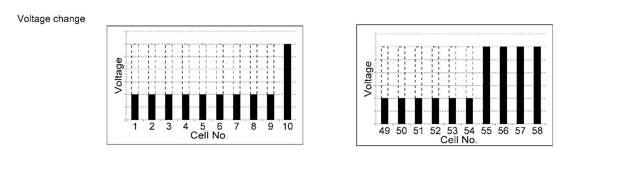
Check with CONSULT, if the voltage fluctuation pattern of abnormal cells applies to any one of the following conditions.
In comparison with the cell controller (ASIC), the voltage of consecutive 12 cell or 13 cell is almost the same and drops.

In comparison with the module, the voltage of consecutive 9 cell or 6 cell is almost the same and drops.
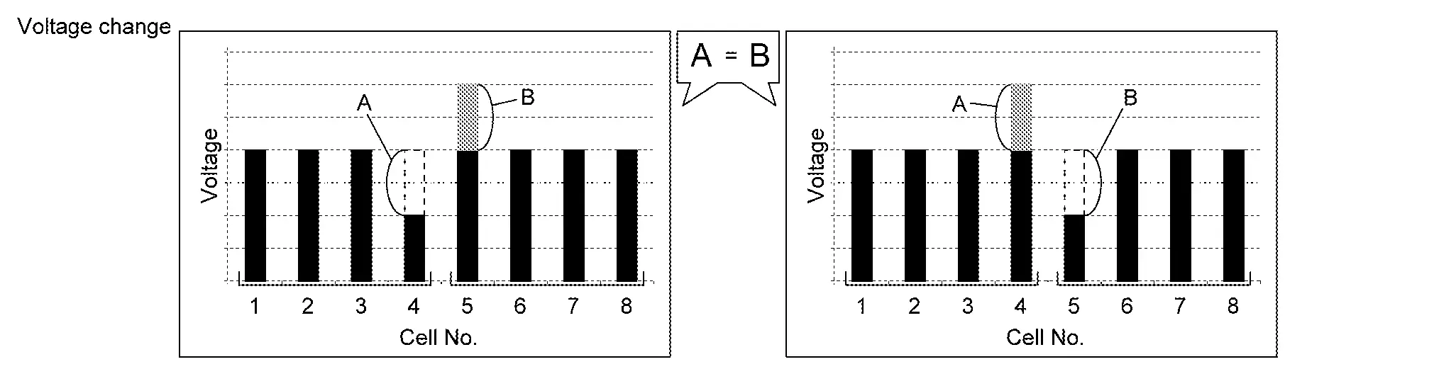
The potential difference between two adjacent cells fluctuates unsymmetrically.

The potential difference between two adjacent cells fluctuates symmetrically.
Does the abnormal cell voltage fluctuation pattern apply to any one of the above conditions?
YES-1>>In comparison with the cell controller (ASIC), the voltage of consecutive 12 cell or 13 cell is almost the same and drops.
Possible malfunction parts: Cell controller internal malfunction (ASIC circuit). Replace cell controller. Refer to Removal & Installation.
YES-2>>In comparison with the module, the voltage of consecutive 9 cell or 6 cell is almost the same and drops.
Possible malfunction parts: Module or cell voltage circuit (Harness connector).GO TO 3.
YES-3>>The potential difference between two adjacent cells fluctuates unsymmetrically.
The potential difference between two adjacent cells fluctuates symmetrically.
Possible malfunction parts: Cell voltage circuit (Harness connector) or cell controller. GO TO 4.
NO>>Does not apply to any one of them.
Possible malfunction parts: Cell, module, cell voltage circuit (Harness connector) or cell controller. GO TO 5.
CHECK CELL VOLTAGE CIRCUIT-1
Check cell voltage circuit (Harness connector) connected to abnormal cells. Refer to Diagnosis Procedure.
Is the inspection result normal?
YES>>Replace corresponding module.
Refer to Disassembly & Assembly.
Refer to Disassembly & Assembly.
Repair or replace malfunctioning parts.
CHECK CELL VOLTAGE CIRCUIT-2
Check cell voltage circuit (Harness connector) connected to abnormal cells. Refer to Diagnosis Procedure.
Is the inspection result normal?
YES>>Replace corresponding cell controller. Refer to Removal & Installation.
NO>>Repair or replace malfunctioning parts.
CHECK CELL VOLTAGE CIRCUIT-3
Check cell voltage circuit (Harness connector) connected to abnormal cells. Refer to Diagnosis Procedure.
Is the inspection result normal?
YES>>GO TO 6.
NO>>Repair or replace malfunctioning parts.
CHECK MODULE VOLTAGE
Check voltage of module corresponding to abnormal cell number. Refer to Component Inspection.
Is the inspection result normal?
YES>>Replace corresponding cell controller. Refer to Removal & Installation.
NO>>GO TO 7.
MODULE REPLACED HISTORY CONFIRMATION
Confirm the latest replacing history of an abnormal module.
Was the module changed?
YES>>Replace corresponding module and cell controller.
Module:
Refer to Disassembly & Assembly.
Refer to Disassembly & Assembly.
Cell controller: Refer to Removal & Installation.
Replace corresponding module.
Refer to Disassembly & Assembly.
Refer to Disassembly & Assembly.
Cell Voltage Circuit Nissan Ariya 1st generation
Diagnosis Procedure
PRECONDITIONING-1
Disconnect the high voltage. Refer to HOW TO DISCONNECT HIGH VOLTAGE : Precautions.
Check voltage of high voltage circuit. Refer to CHECK VOLTAGE IN HIGH VOLTAGE CIRCUIT : Precautions.
Remove Li-ion battery. Refer to Removal & Installation.
Remove battery pack upper case. Refer to Removal & Installation.
GO TO 2.
CHECK CONNECTOR CONNECTION CONDITION
Check the connection of LBC harness connectors and each module stack harness connector.
Is the inspection result normal?
YES>>GO TO 3.
NO>>Repair harness connector connection.
CHECK TOTAL CELL VOLTAGE DETECTION HARNESS CONTINUITY
Disconnect all harness connectors of LBC, each cell controller, and each module stack.
Check resistance value between LBC harness connector, module No.1 (MD1) harness connector and cell controller harness connector.
LBC Cell controller 1 Resistance Connector Terminal Connector Terminal Z469 40 Z465 19 Less than 700 mΩ Z466 15 41 Z465 19 Z466 15 LBC MD1 Resistance Connector Terminal Connector Terminal Z469 40 Z414 6 Less than 700 mΩ 41
Is the inspection result normal?
YES>>GO TO 4.
NO>>Repair harness connector connection.
CHECK CELL VOLTAGE DETECTION HARNESS CONTINUITY
Check resistance value between each cell controller harness connector and each module stack harness connector.
Module No. Cell No. Connector Terminal Cell controller No. Connector Terminal Resistance MD1 CELL01- Z414 6 Cell controller No.1 Z466 15 Less than 700 mΩ CELL02- 1 14 CELL03- 5 4 CELL04- 3 13 CELL05- 12 12 CELL06- 10 11 CELL07- 11 10 CELL08- 9 9 CELL09- 16 3 Module No. Cell No. Connector Terminal Cell controller No. Connector Terminal Resistance MD2 CELL10- Z421 6 Cell controller No.1 Z466 8 Less than 700 mΩ CELL11- 1 2 CELL12- 5 7 CELL13- 3 1 Cell controller No.2 Z463 15 CELL14- 12 14 CELL15- 10 4 CELL16- 11 13 CELL17- 9 12 CELL18- 16 11 Module No. Cell No. Connector Terminal Cell controller No. Connector Terminal Resistance MD3 CELL19- Z420 6 Cell controller No.2 Z463 10 Less than 700 mΩ CELL20- 1 9 CELL21- 5 3 CELL22- 3 8 CELL23- 12 2 CELL24- 10 7 CELL25- 11 1 Cell controller No.3 Z462 15 CELL26- 9 14 CELL27- 16 4 Module No. Cell No. Connector Terminal Cell controller No. Connector Terminal Resistance MD4 CELL28- Z419 6 Cell controller No.3 Z462 13 Less than 700 mΩ CELL29- 1 12 CELL30- 5 11 CELL31- 3 10 CELL32- 12 9 CELL33- 10 3 CELL34- 11 8 CELL35- 9 2 CELL36- 16 7 Module No. Cell No. Connector Terminal Cell controller No. Connector Terminal Resistance MD5 CELL37- Z425 6 Cell controller No.3 Z462 1 Less than 700 mΩ Cell controller No.4 Z459 15 CELL38- 1 14 CELL39- 16 4 CELL40- 4 13 CELL41- 13 12 CELL42- 14 11 Module No. Cell No. Connector Terminal Cell controller No. Connector Terminal Resistance MD6 CELL43- Z424 6 Cell controller No.4 Z459 10 Less than 700 mΩ CELL44- 1 9 CELL45- 16 3 CELL46- 4 8 CELL47- 13 2 CELL48- 14 7 CELL48+ 8 1 Module No. Cell No. Connector Terminal Cell controller No. Connector Terminal Resistance MD7 CELL49- Z423 6 Cell controller No.5 Z477 15 Less than 700 mΩ CELL50- 1 14 CELL51- 16 4 CELL52- 4 13 CELL53- 13 12 CELL54- 14 11 Module No. Cell No. Connector Terminal Cell controller No. Connector Terminal Resistance MD8 CELL55- Z422 6 Cell controller No.5 Z477 10 Less than 700 mΩ CELL56- 1 9 CELL57- 16 3 CELL58- 4 8 CELL59- 13 2 CELL60- 14 7 Module No. Cell No. Connector Terminal Cell controller No. Connector Terminal Resistance MD9 CELL61- Z418 6 Cell controller No.5 Z477 1 Less than 700 mΩ Cell controller No.6 Z475 15 CELL62- 1 14 CELL63- 5 4 CELL64- 3 13 CELL65- 12 12 CELL66- 10 11 CELL67- 11 10 CELL68- 9 9 CELL69- 16 3 Module No. Cell No. Connector Terminal Cell controller No. Connector Terminal Resistance MD10 CELL70- Z417 6 Cell controller No.6 Z475 8 Less than 700 mΩ CELL71- 1 2 CELL72- 5 7 CELL73- 3 1 Cell controller No.7 Z473 15 CELL74- 12 14 CELL75- 10 4 CELL76- 11 13 CELL77- 9 12 CELL78- 16 11 Module No. Cell No. Connector Terminal Cell controller No. Connector Terminal Resistance MD11 CELL79- Z416 6 Cell controller No.7 Z473 10 Less than 700 mΩ CELL80- 1 9 CELL81- 5 3 CELL82- 3 8 CELL83- 12 2 CELL84- 10 7 CELL85- 11 1 Cell controller No.8 Z471 15 CELL86- 9 14 CELL87- 16 4 Module No. Cell No. Connector Terminal Cell controller No. Connector Terminal Resistance MD12 CELL88- Z415 6 Cell controller No.8 Z471 13 Less than 700 mΩ CELL89- 1 12 CELL90- 5 11 CELL91- 3 10 CELL92- 12 9 CELL93- 10 3 CELL94- 11 8 CELL95- 9 2 CELL96- 16 7 CELL96+ 8 1
Is the inspection result normal?
YES>>INSPECTION END
NO>>Repair harness connector connection.
Module Temperature Sensor Nissan Ariya 2026
Diagnosis Procedure
PRECONDITIONING-1
Disconnect the high voltage. Refer to HOW TO DISCONNECT HIGH VOLTAGE : Precautions.
Check voltage of high voltage circuit. Refer to CHECK VOLTAGE IN HIGH VOLTAGE CIRCUIT : Precautions.
Remove Li-ion battery. Refer to Removal & Installation.
Remove battery pack upper case. Refer to Removal & Installation.
GO TO 2.
CHECK CONNECTOR CONNECTION CONDITION
Check the connection of each cell controller harness connectors and each module stack harness connector.
Is the inspection result normal?
YES>>GO TO 3.
NO>>Repair harness connector connection.
CHECK MODULE TEMPERATURE SENSOR
Disconnect each cell controller harness connector.
Check module temperature sensor. Refer to Component Inspection.
Is the inspection result normal?
YES>>GO TO 4.
NO>>Replace malfunction module.
CHECK CONTINUITY BETWEEN MODULE TEMPERATURE SENSOR AND LBC
Disconnect connector of corresponding module.
Check continuity between module harness connector and cell controller harness connector.
MD1 Cell controller No.2 Resistance Connector Terminal Connector Terminal Z414 4 Z463 16 0 Ω approx. 14 6 MD2 Cell controller No.2 Resistance Connector Terminal Connector Terminal Z421 4 Z463 16 0 Ω approx. 14 6 MD3 Cell controller No.3 Resistance Connector Terminal Connector Terminal Z420 4 Z462 16 0 Ω approx. 14 6 MD4 Cell controller No.3 Resistance Connector Terminal Connector Terminal Z419 4 Z462 16 0 Ω approx. 14 6 MD5 Cell controller No.4 Resistance Connector Terminal Connector Terminal Z425 11 Z459 16 0 Ω approx. 10 5 MD6 Cell controller No.4 Resistance Connector Terminal Connector Terminal Z424 11 Z459 16 0 Ω approx. 10 6 MD7 Cell controller No.6 Resistance Connector Terminal Connector Terminal Z423 11 Z475 16 0 Ω approx. 10 5 MD8 Cell controller No.6 Resistance Connector Terminal Connector Terminal Z422 11 Z475 16 0 Ω approx. 10 6 MD9 Cell controller No.7 Resistance Connector Terminal Connector Terminal Z418 4 Z473 16 0 Ω approx. 14 5 MD10 Cell controller No.7 Resistance Connector Terminal Connector Terminal Z417 4 Z473 16 0 Ω approx. 14 6 MD11 Cell controller No.8 Resistance Connector Terminal Connector Terminal Z416 4 Z471 16 0 Ω approx. 14 5 MD12 Cell controller No.8 Resistance Connector Terminal Connector Terminal Z415 4 Z471 16 0 Ω approx. 14 6 Check harnesses for short to ground and short to lines.
Is the inspection result normal?
YES>>INSPECTION END
NO>>Replace or repair Li-ion batter Nissan Ariya vehicle communication harness.
Component Inspection
PRECONDITIONING-1
Disconnect the high voltage. Refer to HOW TO DISCONNECT HIGH VOLTAGE : Precautions.
Check voltage of high voltage circuit. Refer to CHECK VOLTAGE IN HIGH VOLTAGE CIRCUIT : Precautions.
Remove Li-ion battery. Refer to Removal & Installation.
Remove battery pack upper case. Refer to Removal & Installation.
GO TO 2.
CHECK MODULE TEMPERATURE SENSOR
Disconnect each cell controller harness connector.
Check resistance of module temperature sensor.
2P9S Module Measurement Condition Resistance Terminal 4 14 40 °C 18 kΩ approx. 25 °C 10 kΩ approx. 40 °C 5.8 kΩ approx. 2P6S Module Measurement Condition Resistance Terminal 11 10 10 °C 18 kΩ approx. 25 °C 10 kΩ approx. 40 °C 5.8 kΩ approx.
Is the inspection result normal?
YES>>INSPECTION END
NO>>Replace module.
Module Nissan Ariya 2023
Component Inspection
CHECK MODULE VOLTAGE
Check voltage of module.
2P9S (23 Parallel 9 Series)
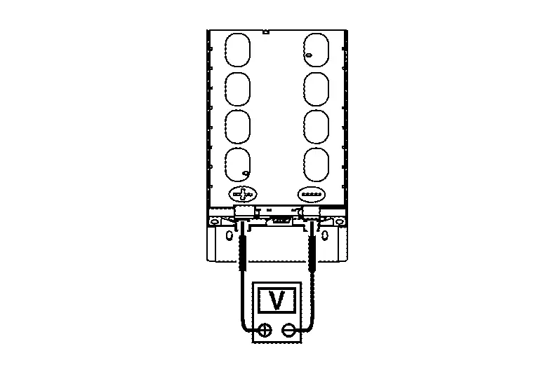
Terminal Voltage + − Module Positive terminal Negative terminal 25.2 - 37.656 V 2P6S (2 Parallel 6 Series)

Terminal Voltage + − Module Positive terminal Negative terminal 16.8 - 25.104 V
Is the inspection result normal?
YES>>INSPECTION END
NO>>Replace module.
Interlock Detection Switch (service Plug) Nissan Ariya: FE0
Diagnosis Procedure
CHECK INSTALLATION CONDITION OF SERVICE PLUG
Check service plug installation condition. Refer to HOW TO DISCONNECT HIGH VOLTAGE : Precautions.
Is the inspection result normal?
YES>>GO TO 2.
NO>>Install service plug properly.
CHECK INTERLOCK DETECTING SWITCH (SERVICE PLUG)
Check interlock detecting switch (Service plug). Refer to Component Inspection.
Is the inspection result normal?
YES>>GO TO 3.
NO>>Replace service plug.
CHECK INSTALLATION CONDITION OF HIGH-VOLTAGE HARNESS CONNECTOR
Check the connection status of high-voltage harness connector (Front) for locking and interlocking.
Is the inspection result normal?
YES>>GO TO 4.
NO>>Connect high-voltage harness connector (front) harness connector properly.
CHECK INTERLOCK DETECTING SWITCH [HIGH VOLTAGE HARNESS CONNECTOR (FRONT)]
Check interlock detecting switch [(High-voltage harness connector(Front)]. Refer to Component Inspection.
Is the inspection result normal?
YES>>GO TO 5.
NO>>Replace Li-ion battery high-voltage harness.
REMOVE LI-ION BATTERY
Remove Li-ion battery. Refer to Removal & Installation.
Remove battery pack upper case. Refer to Removal & Installation.
GO TO 6.
CHECK CONNECTOR CONNECTION CONDITION
Check connection status of LBC harness connector, interlock detecting switch (Service plug) harness connector and interlock detecting switch [High voltage harness connector (Front)] harness connector.
Is the inspection result normal?
YES>>GO TO 7.
NO>>Repair harness connector connection.
CHECK INTERLOCK DETECTING CIRCUIT CONTINUITY
Remove LBC harness connector, interlock detecting switch (Service plug) harness connector and interlock detecting switch [High voltage harness connector (Front)] harness connector.
Check continuity between LBC harness connector and interlock detecting switch (Service plug) harness connector.
LBC Interlock detecting switch
(Service plug)Continuity Connector Terminal Connector Terminal Z468 21 Z404 3 Exist Check harness for short to ground and short to lines.
Check continuity between interlock detecting switch (Service plug) harness connector and interlock detecting switch [high voltage harness connector (front)] harness connector.
Interlock detecting switch
(Service plug)Interlock detecting switch
[High voltage harness connector (Front)]Continuity Connector Terminal Connector Terminal Z404 4 Z407 1 Exist Check harness for short to ground and short to lines.
Check continuity between interlock detecting switch [High voltage harness connector (Front)] and LBC harness connector.
Interlock detecting switch
[High voltage harness connector (Front)]LBC Continuity Connector Terminal Connector Terminal Z407 2 Z468 31 Exist Check harness for short to ground and short to lines.
GO TO 8.
NO>>Repair or replace Li-ion battery Nissan Ariya vehicle communication harness.
CHECK HIGH VOLTAGE HARNESS CONNECTOR (FRONT)
Check continuity between high voltage harness connector and interlock detecting switch (High voltage harness) harness connector.
High voltage harness connector (Front) Interlock detecting switch
[High voltage harness connector (Front)]Continuity Connector Terminal Connector Terminal Z445 2 Z407 2 Exist 1 1 Check harness for short to ground and short to lines.
INSPECTION END
NO>>Replace high voltage harness connector. Refer to Disassembly & Assembly.
Component Inspection
SERVICE PLUG REMOVING
Remove the service plug. Refer to HOW TO DISCONNECT HIGH VOLTAGE : Precautions.
GO TO 2.
CHECK INTERLOCK DETECTING SWITCH (SERVICE PLUG)
Check visually that the terminals are not a corrosion, a bend, a break or a damage.
Check the continuity between terminals.
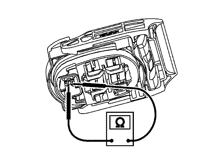
| Value: | 0 Ω approx. |
Is the inspection result normal?
YES>>INSPECTION END
NO>>Replace service plug.
Battery Current Sensor Circuit Nissan Ariya 1st generation
Diagnosis Procedure
PRECONDITIONING-1
Disconnect the high voltage. Refer to HOW TO DISCONNECT HIGH VOLTAGE : Precautions.
Check voltage of high voltage circuit. Refer to CHECK VOLTAGE IN HIGH VOLTAGE CIRCUIT : Precautions.
Remove Li-ion battery. Refer to Removal & Installation.
Remove battery pack upper case. Refer to Removal & Installation.
GO TO 2.
CHECK CONNECTOR CONNECTION CONDITION
Check the connection status of the LBC harness connector and junction box harness connectors.
Is the inspection result normal?
YES>>GO TO 3.
NO>>Repair harness connector connection.
CHECK CONTINUITY BETWEEN BATTERY CURRENT SENSOR (BATTERY JUNCTION BOX) AND LBC HARNESS CONNECTOR
Remove LBC harness connector and battery junction box harness connector.
Check continuity LBC harness connector and battery junction box harness connector.
Battery junction box LBC Continuity Connector Terminal Connector Terminal Z413 11 Z468 17 Exist 12 18 13 Z467 9 14 3 Check harness for short to ground and short to lines.
Is inspection result normal?
YES>>Replace battery junction box. Refer to Disassembly & Assembly.
NO>>Repair or replace Li-ion battery Nissan Ariya vehicle communication harness.
Battery Pack Water Temperature Sensor Circuit Nissan Ariya SUV
Diagnosis Procedure
PRECONDITIONING-1
Disconnect the high voltage. Refer to HOW TO DISCONNECT HIGH VOLTAGE : Precautions.
Check voltage of high voltage circuit. Refer to CHECK VOLTAGE IN HIGH VOLTAGE CIRCUIT : Precautions.
Remove Li-ion battery. Refer to Removal & Installation.
Remove battery pack upper case. Refer to Removal & Installation.
GO TO 2.
CHECK CONNECTOR CONNECTION CONDITION
Check the connection status of the LBC harness connector and battery pack water temperature sensor harness connector.
Is the inspection result normal?
YES>>GO TO 3.
NO>>Repair harness connector connection.
CHECK BATTERY PACK WATER TEMPERATURE SENSOR
Disconnect battery pack water temperature sensor harness connector.
Check battery pack water temperature sensor. Refer to Component Inspection.
Is the inspection result normal?
YES>>GO TO 4.
NO>>Replace battery pack water temperature sensor.
CHECK CONTINUITY BETWEEN BATTERY PACK WATER TEMPERATURE SENSOR AND LBC
Remove LBC connector.
Check continuity between battery pack water temperature sensor harness connector and LBC harness connector.
Battery pack water temperature sensor LBC Continuity Connector Terminal Connector Terminal Z411 1 Z468 23 Exist 2 24 Check harness for short to ground and short to lines.
Is inspection result normal?
YES>>INSPECTION END
NO>>Repair or replace Li-ion battery Nissan Ariya vehicle communication harness.
Component Inspection
PRECONDITIONING
Disconnect the high voltage. Refer to HOW TO DISCONNECT HIGH VOLTAGE : Precautions.
Check voltage of high voltage circuit. Refer to CHECK VOLTAGE IN HIGH VOLTAGE CIRCUIT : Precautions.
Remove Li-ion battery. Refer to Removal & Installation.
Remove battery pack upper case. Refer to Removal & Installation.
GO TO 2.
CHECK BATTERY PACK WATER TEMPERATURE SENSOR
Disconnect battery pack water temperature sensor harness connector.
Check resistance of battery pack water temperature sensor.
Battery pack water temperature sensor Condition Resistance Terminal 1 2 25 °C 3960 Ω - 4040 Ω
Is the inspection result normal?
YES>>INSPECTION END
NO>>Replace battery pack water temperature sensor.
Battery Coolant Heater (ptc) Nissan Ariya first Gen
Diagnosis Procedure
PRECONDITIONING-1
Disconnect the high voltage. Refer to HOW TO DISCONNECT HIGH VOLTAGE : Precautions.
Check voltage of high voltage circuit. Refer to CHECK VOLTAGE IN HIGH VOLTAGE CIRCUIT : Precautions.
GO TO 2.
CHECK CONTINUITY BATTERY PTC Nissan Ariya Vehicle COMMUNICATION CIRCUIT
Remove vehicle communication harness connector and vehicle communication harness connector (Battery PTC) connector.
Check continuity between Nissan Ariya vehicle communication harness connector and vehicle communication harness connector (Battery PTC) and vehicle communication harness connector (Battery PTC).
Nissan Ariya Vehicle communication harness connector Vehicle communication harness connector
(Battery PTC)Continuity Connector Terminal Connector Terminal Z405 17 Z401 15 Exist 27 17 30 23 Check harness for short to ground and short to lines.
Is inspection result normal?
YES>>When checking only battery PTC Nissan Ariya vehicle communication: INSPECTION END
When also checking battery high voltage circuit: GO TO 5.
GO TO 3.
PRECONDITIONING-2
Remove Li-ion battery from Nissan Ariya vehicle. Refer to Removal & Installation.
Remove battery pack upper case. Refer to Removal & Installation.
GO TO 4.
CHECK CONNECTOR CONNECTING CONDITION
Check connection status of intermediate connector (Z402).
Is the inspection result normal?
YES>>Repair replace Li-ion battery Nissan Ariya vehicle communication harness.
NO>>Repair harness connector connection.
PRECONDITIONING-3
Remove Li-ion battery from Nissan Ariya vehicle. Refer to Removal & Installation.
Remove battery pack upper case. Refer to Removal & Installation.
GO TO 6.
CHECK CONNECTOR CONNECTING CONDITION
Check connection status of the junction box connector (Z409 and Z408), and intermediate connector (Z478 and Z429).
Is the inspection result normal?
YES>>GO TO 7.
NO>>Repair harness connector connection.
CHECK BATTERY PTC FUSE
Check battery PTC fuse. Refer to Component Inspection.
Is the inspection result normal?
YES>>GO TO 8.
NO>>Replace junction box.
CHECK CONTINUITY BETWEEN HARNESS CONNECTORS OF JUNCTION BOX AND BATTERY PTC.
Remove harness connectors of junction box and battery PTC.
Check continuity between harness connectors of junction box and battery PTC.
Junction box Battery PTC Continuity Connector Terminal Connector Terminal Z409 P12 Z448 N 0Ω approx. Z408 P11 P
Is the inspection result normal?
YES>>INSPECTION END
NO>>Replace high voltage harness battery PTC.
High Voltage Fuse Nissan Ariya 2026
Component Inspection
REMOVE BATTERY PACK
Remove Li-ion battery from Nissan Ariya vehicle. Refer to Removal & Installation.
Remove battery pack upper case. Refer to Removal & Installation.
Remove junction box cover.
GO TO 2.
CHECK HIGH VOLTAGE FUSE (MAIN)
Check continuity of high voltage fuse (Main).
High voltage fuse (Main)
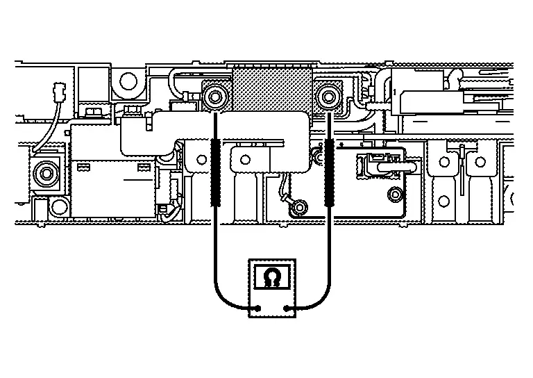
Value: 0 Ω approx. High voltage fuse (Quick charge)
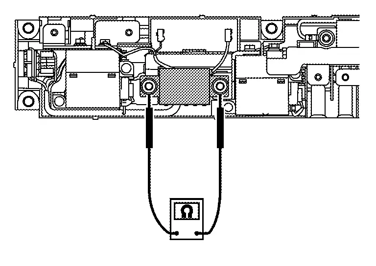
Value: 0 Ω approx. PTC fuse
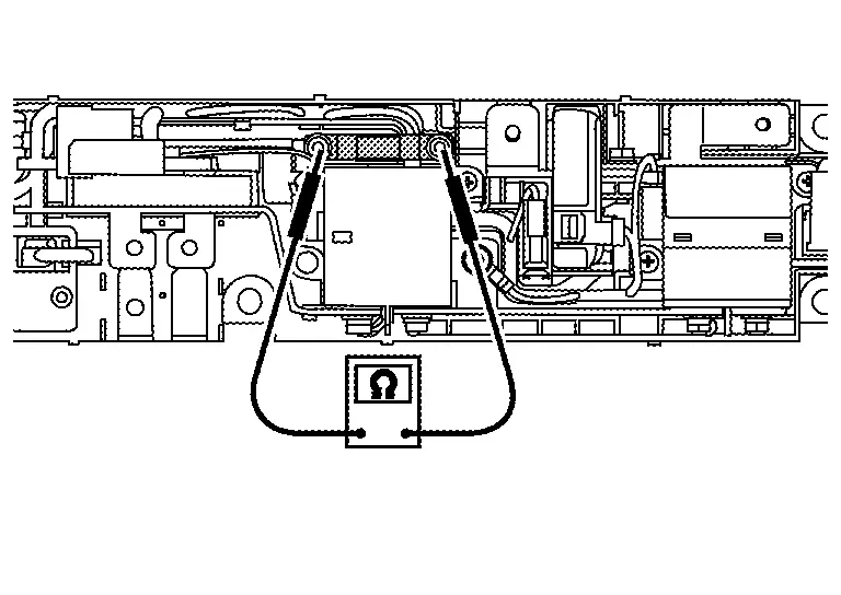
Value: 0 Ω approx.
Is the inspection result normal?
YES>>INSPECTION END
NO>>Replace junction box.
Li-Ion Battery Insulation Resistance Loss Inspection. 2wd Nissan Ariya 2026
Diagnosis Procedure
CHECK MAXIMUM CELL VOLTAGE
With CONSULT
Power switch ON.
Select “Data Monitor” of “HIGH VOLTAGE BATTERY”.
Record “Maximum cell voltage”.
GO TO 2.
PRECONDITIONING
Disconnect the high voltage. Refer to HOW TO DISCONNECT HIGH VOLTAGE : Precautions.
Check voltage in high voltage circuit. Refer to CHECK VOLTAGE IN HIGH VOLTAGE CIRCUIT : Precautions.
Remove Li-ion battery. Refer to Removal & Installation.
Remove battery pack upper case. Refer to Removal & Installation.
Remove LBC. Refer to Removal & Installation.
GO TO 3.
CHECK INSULATION RESISTANCE OF HIGH-VOLTAGE CONNECTOR (FRONT) AND HIGH-VOLTAGE CONNECTOR (QUICK CHARGE)
Using insulation resistance tester, measure insulation resistance between terminals of high-voltage connector (front) and high voltage connector (quick charge).
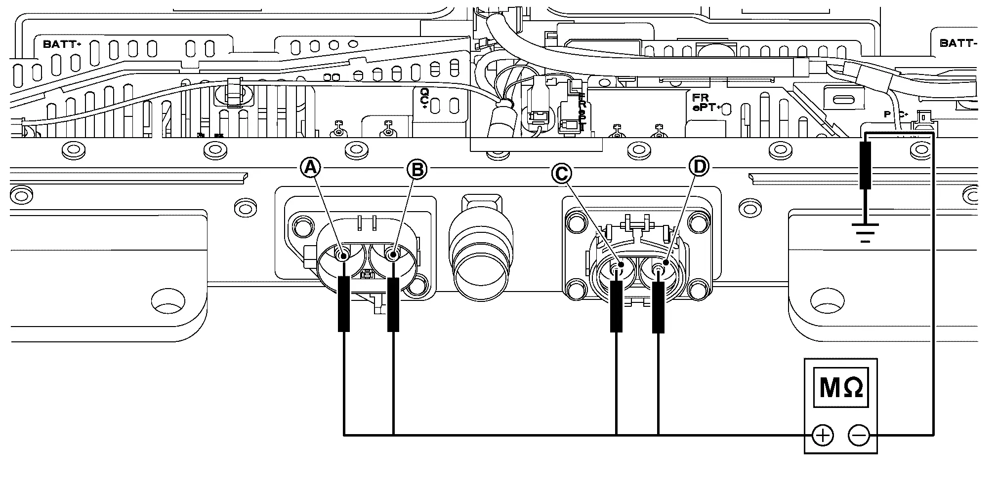
| Probe | Resistance | |
|---|---|---|
| + | − | |
High-voltage connector (Front) terminal |
Battery pack lower case | 1000 MΩ or more |
High-voltage connector (Front) terminal |
||
High-voltage connector (Quick charge) terminal |
||
High-voltage connector (Quick charge) terminal |
||
If used incorrectly, there is the danger of electric shock. If used in the Nissan Ariya vehicle 12 V system, there is the danger of damage to electronic devices. Read the insulation resistance tester instruction manual carefully and be sure to work safely.
Is the inspection result normal?
YES>>GO TO 6.
NO>>GO TO 4.
CHECK BUS BAR BETWEEN HIGH VOLTAGE CONNECTOR AND JUNCTION BOX.
Remove high voltage connector (front) and high voltage connector (quick charge).
Remove each connector of junction box.
Remove the following bus bar.
Bus bar (Bus bar 1) between high voltage connector (Front) and junction box.
Bus bar (Bus bar 20) between high voltage connector (Quick charge) and junction box.
Check that each bus bar shield have no scratches and cracks.
Is the inspection result normal?
YES>>GO TO 5.
NO>>Take note about replaced malfunction parts. Then GO TO 5.
BATTERY JUNCTION BOX INSULATION RESISTANCE-1
Remove high voltage connector (Front) and high voltage connector (Quick charge).
Remove each connector of junction box.
Using insulation resistance tester, measure insulation resistance between battery junction box terminals and battery pack ground.
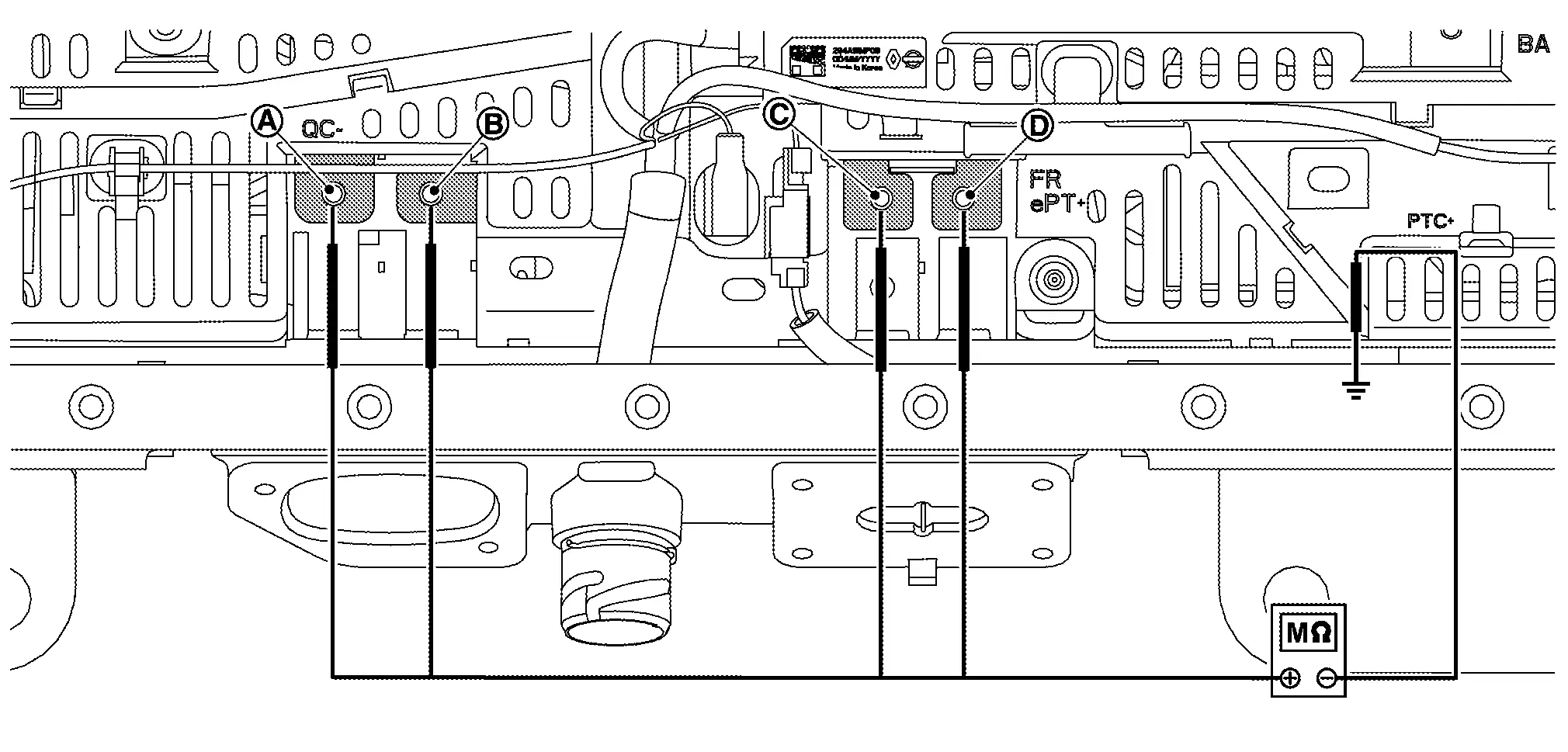
Probe Resistance + − Battery junction box terminals (P1) Battery pack lower case 1000 MΩ or more Battery junction box terminals (P3) Battery junction box terminals (P5) Battery junction box terminals (P6)
Is the inspection result normal?
YES>>Take note about replacement of high voltage connector (Front) and high voltage connector (Quick charge) Then GO TO 6.
NO>>Take note about malfunction parts. Then GO TO 6.
CHECK INSULATION RESISTANCE OF HIGH VOLTAGE CONNECTOR (BATTERY PTC CONNECTOR)
Using insulation resistance tester, measure insulation resistance between high-voltage connector (Battery PTC) terminals and battery pack ground (battery pack lower case).

| Probe | Resistance | |
|---|---|---|
| + | − | |
| High-voltage connector (Battery PTC) terminal |
Battery pack lower case | 1000 MΩ or more |
| High-voltage connector (Battery PTC) terminal |
||
Is the inspection result normal?
YES>>GO TO 8.
NO>>GO TO 7.
CHECK INSULATION RESISTANCE BETWEEN HARNESSES OF BATTERY PTC AND JUNCTION BOX
Remove battery PTC connector of junction box.
Using insulation resistance tester, measure insulation resistance between battery PTC harness and battery pack lower case.
Probe Resistance + − High-voltage connector (Battery PTC) terminal Battery pack lower case 1000 MΩ or more High-voltage connector (Battery PTC) terminal
Is the inspection result normal?
YES>>Record replacement of high voltage connector (Battery PTC) Then GO TO 8.
NO>>Record replacement of harnesses between battery PTC and junction box. Then GO TO 8.
CHECK BUS BAR BETWEEN JUNCTION BOX AND MODULE
Remove the following parts.
Bus bar (bas bar2) between junction box and module No.1.
Bus bar (bas bar19) between junction box and module No.12.
Check that each bus bar shield have no scratches and cracks.
Is the inspection result normal?
YES>>GO TO 9.
NO>>Record replacement of malfunction parts. Then GO TO 9.
CHECK INSULATION RESISTANCE OF BATTERY JUNCTION BOX
Using insulation resistance tester, measure insulation resistance between battery junction box and battery pack lower case.
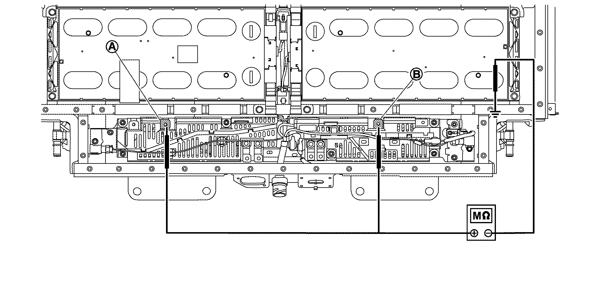
| Probe | Resistance | |
|---|---|---|
| + | − | |
| Battery junction box terminals (P2) |
Battery pack lower case | 1000 MΩ or more |
| Battery junction box terminals (P4) |
||
Is the inspection result normal?
YES>>GO TO 10.
NO>>Record replacement of junction box. Then GO TO 10.
CHECK BUS BAR BETWEEN SERVICE PLUG SWITCH AND MODULE
Remove the following parts.
Bus bar (Bas bar8) between service plug and module No.6
Bus bar (Bas bar13) between service plug and module No.13.
Check that each bus bar shield have no scratches and cracks.
Is the inspection result normal?
YES>>GO TO 11.
NO>>Record replacement of malfunction parts. Then GO TO 11.
CHECK INSULATION RESISTANCE OF SERVICE PLUG SWITCH
Remove service plug switch bracket together with bus bar.
Remove bus bar
from service plug.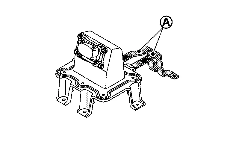
Check that each bus bar shield have no scratches and cracks.
Using insulation resistance tester, measure insulation resistance between service plug switch terminal
and service plug switch bracket.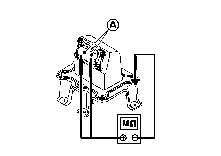
+ − Resistance Service plug switch terminals Service plug switch bracket. 1000 MΩ or more
Is the inspection result normal?
YES>>GO TO 12.
NO>>Record replacement of malfunction parts. Then GO TO 12.
CHECK EACH BUS BAR
Remove the following bus bars.
Bus bar (Bus bar 3) between module No.1 and module No.2
Bus bar (Bus bar 4) between module No.2 and module No.3
Bus bar (Bus bar 5) between module No.3 and module No.4
Bus bar (Bus bar 6) between module No.4 and module No.5
Bus bar (Bus bar 7) between module No.5 and module No.6
Bus bar (Bus bar 14) between module No.7 and module No.7
Bus bar (Bus bar 15) between module No.8 and module No.8
Bus bar (Bus bar 16) between module No.9 and module No.9
Bus bar (Bus bar 17) between module No.10 and module No.10
Bus bar (Bus bar 18) between module No.11 and module No.12
Check that each bus bar shield have no scratches and cracks.
Is the inspection result normal?
YES>>GO TO 13.
NO>>Record replacement of malfunction parts. Then GO TO 13.
CHECK INSULATION VOLTAGE OF MODULE
Disconnect cell voltage detecting connector of each module.
Measure voltage between positive and negative terminal of each module and battery lower case ground.
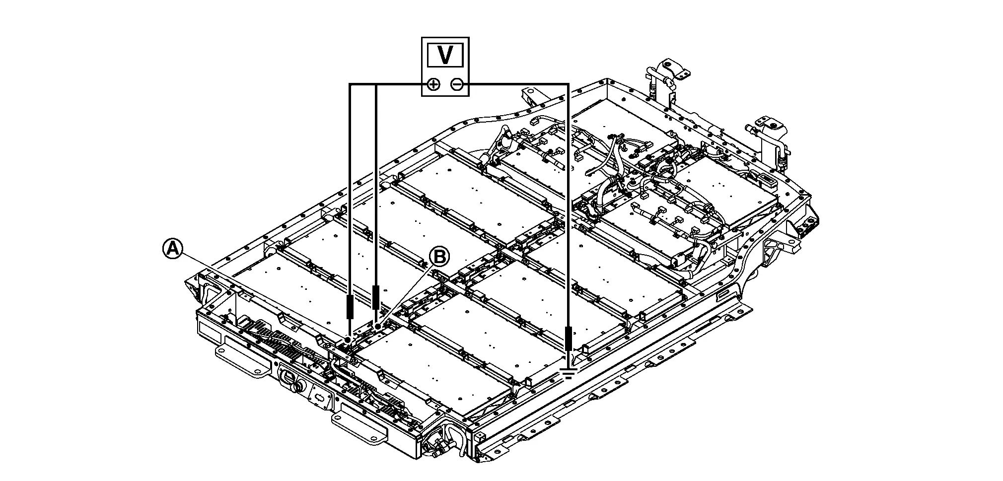
Probe Resistance + − Module positive terminal Battery pack lower case 0 V approx. Module negative terminal
Is the inspection result normal?
YES>>GO TO 14.
NO>>GO TO 15.
CHECK RESULT CONFIRMATION
Confirm malfunction parts written or record by check.
Is there malfunction parts?
YES>>Replace all parts written down or recorded.
NO>>Replace LBC.
MODULE APPEARANCE CHECK
Remove the module that has malfunction at voltage leak check from battery pack lower case.
Check the module for any of the following abnormalities by comparing its appearance with other normal modules.
There are dents or deformation on the module surface.
Liquid adheres to the module surface.
Module emits a strong organic solvent-like odor and continues.
Record replacement of malfunction module and GO TO 14.