Component Parts /circuit Diagnosis
- Power Supply and Ground Circuit (vcm)
- Accelerator Pedal Position Sensor
- Active Grille Shutter 1
- Charge Connector Lock Actuator
- Charge Connector Lock Status Detection Signal Circuit
- Charging Status Indicator
- Charge Port Light
- Charge Port Lid Actuator
- Cooling Fan
- Electric Water Pump Relay
- Electric Water Pump 1
- Ev Power Relay
- Evse Connecting Signal Circuit
- High Voltage Junction Box Temperature Sensor
- Immediate Charging Switch
- Insulation Resistance (high Voltage Harness)
- Pre-Charge Relay Circuit
- Quick Charge Relay Circuit
- Refrigerant Pressure Sensor
- Stop Lamp Switch
- Traction Motor Oil Pump Relay
- Quick Charger Port Temperature Sensor Circuit
Power Supply and Ground Circuit (vcm) Nissan Ariya 2023
Diagnosis Procedure
CHECK FUSE
Check that the fuses below are not blown.
| Power supply | Fuse number |
|---|---|
| 12 V battery power supply | 93 |
| 103 | |
| Power switch ON power supply | 140 |
Is the inspection result normal?
YES>>GO TO 2.
NO>>Replace the fuse after repairing the applicable circuit.
CHECK VCM GROUND CIRCUIT
Power switch OFF.
Disconnect VCM harness connector.
Check for continuation between the VCM harness connector and ground.
+ − Continuity VCM Connector Terminal E46 28 Ground Existing 29 32
Is the inspection result normal?
YES>>GO TO 3.
NO>>Repair or replace error-detected parts.
CHECK 12 V BATTERY POWER SUPPLY-1
Install any removed fuses.
Check voltage between the VCM harness connector and ground.
+ − Voltage VCM Connector Terminal E48 153 Ground 12 V battery power supply voltage
Is the inspection result normal?
YES>>GO TO 5.
NO>>GO TO 4.
CHECK 12 V BATTERY POWER SUPPLY CIRCUIT
Remove fuse #93.
Check for continuation between fuse #93 and the VCM harness connector.
+ − Continuity VCM Connector Terminal Fuse #93 terminal E48 153 Existing Also check harness for short to ground.
Is the inspection result normal?
YES>>Check 12 V battery power supply circuit.
NO>>Repair or replace error-detected parts.
CHECK 12 V BATTERY POWER SUPPLY-2
Check voltage between the VCM harness connector and ground.
| + | − | Voltage | |
|---|---|---|---|
| VCM | |||
| Connector | Terminal | ||
| E48 | 158 | Ground | 12 V battery power supply voltage |
Is the inspection result normal?
YES>>GO TO 7.
NO>>GO TO 6.
CHECK 12 V BATTERY POWER SUPPLY CIRCUIT
Remove fuse #103.
Check for continuation between fuse #103 and the VCM harness connector.
+ − Continuity VCM Connector Terminal Fuse #103 terminal E48 158 Existing Also check harness for short to ground.
Is the inspection result normal?
YES>>Check 12 V main relay and 12 V battery power supply circuit.
NO>>Repair or replace error-detected parts.
CHECK POWER SWITCH ON POWER SUPPLY
Power switch ON.
Check voltage between the VCM harness connector and ground.
+ − Voltage VCM Connector Terminal E46 13 Ground 12 V battery power supply voltage
Is the inspection result normal?
YES>>INSPECTION END
NO>>GO TO 8.
CHECK POWER SWITCH ON POWER SUPPLY CIRCUIT
Power switch OFF.
Disconnect IPDM E/R harness connector.
Check for continuation between the VCM harness connector and the IPDM E/R harness connector.
+ − Continuity IPDM E/R VCM Connector Terminal Connector Terminal E39 70 E46 13 Existing Also check harness for short to ground.
Is the inspection result normal?
YES>>Check IGN relay and power switch ON power supply circuit.
NO>>Repair or replace error-detected parts.
Accelerator Pedal Position Sensor Nissan Ariya: FE0
Diagnosis Procedure
CHECK ACCELERATOR PEDAL POSITION SENSOR POWER SUPPLY-1
Power switch OFF.
Disconnect accelerator pedal position sensor harness connector.
Power switch ON.
Check voltage between the accelerator pedal position sensor harness connector terminals.
Accelerator pedal position sensor Voltage
(Approx.)Sensor Connector + − Terminal 1 E8 3 5 5 V 2 2 6
Is the inspection result normal?
YES>>GO TO 6.
NO>>GO TO 2.
CHECK ACCELERATOR PEDAL POSITION SENSOR POWER SUPPLY-2
Check voltage between the accelerator pedal position sensor harness connector and ground.
| + | − | Voltage (Approx.) | ||
|---|---|---|---|---|
| Accelerator pedal position sensor | ||||
| Sensor | Connector | Terminal | ||
| 1 | E8 | 3 | Ground | 5 V |
| 2 | 2 | |||
Is the inspection result normal?
YES>>GO TO 4.
NO>>GO TO 3.
CHECK ACCELERATOR PEDAL POSITION SENSOR POWER SUPPLY CIRCUIT
Power switch OFF.
Disconnect VCM harness connector.
Check for continuation between the accelerator pedal position sensor harness connector and the VCM harness connector.
+ − Continuity Accelerator pedal position sensor VCM Sensor Connector Terminal Connector Terminal 1 E8 3 E46 26 Existing 2 2 22 Also check harness for short to power supply and ground.
Is the inspection result normal?
YES>>Perform VCM power supply and ground inspection. Refer to Diagnosis Procedure.
NO>>Repair or replace error-detected parts.
CHECK ACCELERATOR PEDAL POSITION SENSOR GROUND CIRCUIT
Power switch OFF.
Disconnect VCM harness connector.
Check for continuation between the accelerator pedal position sensor harness connector and the VCM harness connector.
+ − Continuity Accelerator pedal position sensor VCM Sensor Connector Terminal Connector Terminal 1 E8 5 E46 31 Existing 2 6 24 Also check harness for short to power supply.
Is the inspection result normal?
YES>>GO TO 5.
NO>>Repair or replace error-detected parts.
CHECK VCM GROUND CIRCUIT
Check for continuation between the VCM harness connector and ground.
| + | − | Continuity | |
|---|---|---|---|
| VCM | |||
| Connector | Terminal | ||
| E46 | 28 | Ground | Existing |
| 29 | |||
| 32 | |||
Is the inspection result normal?
YES>>INSPECTION END
NO>>Repair or replace error-detected parts.
CHECK ACCELERATOR PEDAL POSITION SENSOR SIGNAL CIRCUIT
Power switch OFF.
Disconnect VCM harness connector.
Check for continuation between the accelerator pedal position sensor harness connector and the VCM harness connector.
+ − Continuity Accelerator pedal position sensor VCM Sensor Connector Terminal Connector Terminal 1 E8 4 E46 30 Existing 2 1 23 Also check harness for short to power supply and ground.
Is the inspection result normal?
YES>>GO TO 7.
NO>>Repair or replace error-detected parts.
CHECK ACCELERATOR PEDAL POSITION SENSOR
Check accelerator pedal position sensor. Refer to Component Inspection.
Is the inspection result normal?
YES>>INSPECTION END
NO>>Repair or replace error-detected parts.
Component Inspection
CHECK ACCELERATOR PEDAL POSITION SENSOR
Power switch OFF.
Reconnect all disconnected harness connectors.
Power switch ON.
Check voltage between the VCM harness connector terminals.
VCM Condition Voltage (V) Connector + – Terminal Terminal E46 30 (Accelerator pedal position sensor 1) 31 Accelerator pedal Fully closed 0.6 – 0.9 Fully open 3.9 – 4.8 23 (Accelerator pedal position sensor 2) 24 Fully closed 0.3 – 0.45 Fully open 1.95 – 2.4
Is the inspection result normal?
YES>>INSPECTION END
NO>>Replace accelerator pedal assembly. Refer to ACCELERATOR CONTROL SYSTEM : Removal & Installation.
Active Grille Shutter 1 Nissan Ariya
Diagnosis Procedure
CHECK ACTIVE GRILLE SHUTTER 1 STATE
Power switch OFF.
Check active grille shutter 1 for operation interference from foreign matter.
Check active grille shutter 1 installation condition.
Is the inspection result normal?
YES>>GO TO 2.
NO>>Repair or replace error-detected parts.
CHECK ACTIVE GRILLE SHUTTER 1 POWER SUPPLY
Disconnect active grille shutter 1 harness connector.
Check voltage between the active grille shutter 1 harness connector and ground.
+ − Voltage Active grille shutter 1 Connector Terminal E60 1 Ground 12 V battery voltage
Is the inspection result normal?
YES>>GO TO 4.
NO>>GO TO 3.
CHECK FUSE
Remove fuse #105.
Check that the fuse is not blown.
Is the inspection result normal?
YES>>Check battery power supply circuit.
NO>>Replace the fuse after repairing the applicable circuit.
CHECK ACTIVE GRILLER SHUTTER 1 GROUND CIRCUIT
Check for continuation between the active grille shutter 1 harness connector and ground.
+ − Continuity Active grille shutter 1 Connector Terminal E60 4 Ground Existing Also check harness for short.
Is the inspection result normal?
YES>>GO TO 5.
NO>>Repair or replace error-detected parts.
CHECK ACTIVE GRILLE SHUTTER 1 INPUT SIGNAL CIRCUIT
Disconnect VCM harness connector.
Check for continuation between the VCM harness connector and the active grille shutter 1 harness connector.
+ − Continuity VCM Active grille shutter 1 Connector Terminal Connector Terminal E48 99 E60 3 Existing Also check harness for short to power supply and ground.
Is the inspection result normal?
YES>>GO TO 6.
NO>>Repair or replace error-detected parts.
CHECK ACTIVE GRILLE SHUTTER 1
Check active grille shutter 1. Refer to Component Inspection.
Is the inspection result normal?
YES>>INSPECTION END
NO>>Replace active grille shutter. Refer to Removal & Installation.
Component Inspection
CHECK ACTIVE GRILLLE SHUTTER 1
 With CONSULT
Set the Nissan Ariya vehicle to READY.
Select “Active grille shutter 1” in “ACTIVE TEST MODE” of “EV/HEV” using CONSULT.
Touch “Position adjustment”.
After calibration is finished, check the active grille shutter 1 operation under the conditions below.
Condition Active grille shutter 1 Select “Close” Open ⇒ Closed Select “Open” Closed ⇒ Open
 Without CONSULT
Power switch OFF.
Set the shutter to a closed state by hand.
Check the active grille shutter 1 operation under the condition below.
Condition Active grille shutter 1 Power switch ON Closed ⇒ Open
Is the inspection result normal?
YES>>INSPECTION END
NO>>Replace active grille shutter. Refer to Removal & Installation.
Charge Connector Lock Actuator Nissan Ariya SUV
Diagnosis Procedure
CHECK CHARGE CONNECTOR LOCK ACTUATOR CIRCUIT
Power switch OFF.
Disconnect VCM harness connector and charge connector lock actuator harness connector.
Check for continuation between the VCM harness connector and the charge connect lock actuator harness connector.
+ − Continuity VCM Charge port Connector Terminal Connector Terminal E47 94 E27 15 Existing 95 14 Also check harness for short to power supply and ground.
Is the inspection result normal?
YES>>GO TO 2.
NO>>Repair or replace error-detected parts.
CHECK CHARGE CONNECTOR LOCK ACTUATOR
Check charge connector lock actuator. Refer to Component Inspection.
Is the inspection result normal?
YES>>INSPECTION END
NO>>Replace charge port. Refer to CHARGE PORT : Removal & Installation.
Component Inspection
CHECK CHARGE CONNECTOR LOCK ACTUATOR
Power switch OFF.
Remove charge port. Refer to CHARGE PORT : Removal & Installation.
Apply 12 V power supply to the terminals below and check charge connector lock actuator operation.
Charge port Operation Connector Terminal + - E27 14 15 Operating 15 14
Is the inspection result normal?
YES>>INSPECTION END
NO>>Replace charge port. Refer to CHARGE PORT : Removal & Installation.
Charge Connector Lock Status Detection Signal Circuit Nissan Ariya first Gen
Diagnosis Procedure
CHECK CHARGE PORT
Power switch OFF.
Disconnect charge port Nissan Ariya vehicle side harness connector.
Check the charge port. Refer to Component Inspection.
Is the inspection result normal?
YES>>GO TO 2
NO>>Replace charge port. Refer to CHARGE PORT : Removal & Installation.
CHECK CHARGE CONNECTOR LOCK STATUS DETECTION SIGNAL CIRCUIT CONTINUITY
Disconnect VCM Nissan Ariya vehicle side harness connector.
Check for continuation between the charge port vehicle side harness connector and the VCM Nissan Ariya vehicle side harness connector.
Charge port VCM Continuity Connector Terminal Connector Terminal E27 16 E47 62 Existing Also check harness for short to ground and short between harnesses.
Is the inspection result normal?
YES>>Perform trouble cause simulation test. Refer to Intermittent Incident.
NO>>Repair or replace error-detected parts.
Charging Status Indicator Nissan Ariya 2026
Component Function Check
CHECK CHARGING STATUS INDICATOR FUNCTION
Connect the quick charge coupler or the normal charge coupler to the Nissan Ariya vehicle.
Check that the charging port light lights up.
Is the inspection result normal?
YES>>INSPECTION END
NO>>Refer to Diagnosis Procedure.
Diagnosis Procedure
CHECK CHARGING STATUS INDICATOR POWER SUPPLY
Power switch OFF.
Disconnect charging status indicator harness connector.
Check voltage between the charging status indicator harness connector and ground.
+ − Voltage Charging status indicator Connector Terminal M28 1 Ground 12 V battery voltage
Is the inspection result normal?
YES>>GO TO 4.
NO>>GO TO 2.
CHECK FUSE
Remove fuse #27 and check that it is not blown.
Is the inspection result normal?
YES>>GO TO 3
NO>>Replace the fuse after repairing the applicable circuit.
CHECK CHARGING STATUS INDICATOR POWER SUPPLY CIRCUIT
Check for continuation between the charging status indicator harness connector and fuse terminal.
+ − Continuity Charging status indicator Connector Terminal M28 1 #27 fuse terminal Existing Also check harness for short to power supply and ground.
Is the inspection result normal?
YES>>Check power supply circuit.
NO>>Repair or replace error-detected parts.
CHECK CHARGING STATUS INDICATOR GROUND CIRCUIT
Check for continuation between the charging status indicator harness connector and ground.
| + | − | Continuity | |
|---|---|---|---|
| Charging status indicator | |||
| Connector | Terminal | ||
| M28 | 3 | Ground | Existing |
Is the inspection result normal?
YES>>GO TO 5.
NO>>Repair or replace error-detected parts.
CHECK CHARGING STATUS INDICATOR CONTROL CIRCUIT
Disconnect VCM harness connector.
Check for continuation between the charging status indicator harness connector and the VCM harness connector.
+ − Continuity Charging status indicator VCM Connector Terminal Connector Terminal M28 2 E47 41 Existing Also check harness for short to power supply and ground.
Is the inspection result normal?
YES>>GO TO 6.
NO>>Repair or replace error-detected parts.
TROUBLE CAUSE SIMULATION TEST
Perform trouble cause simulation test. Refer to Intermittent Incident.
Is the inspection result normal?
YES>>Replace charging status indicator. Refer to CHARGING STATUS INDICATOR : Removal & Installation.
NO>>Repair or replace error-detected parts.
Charge Port Light Nissan Ariya
Component Function Check
CHECK CHARGE PORT LIGHT FUNCTION
After closing the Nissan Ariya vehicle door, set it to an open state.
Check that the charge port light lights up.
Is the inspection result normal?
YES>>INSPECTION END
NO>>Refer to Diagnosis Procedure.
Diagnosis Procedure
CHECK CHARGE PORT LIGHT POWER SUPPLY
Power switch OFF.
Disconnect charge port light harness connector.
After closing the Nissan Ariya vehicle door, set it to an open state.
Measure voltage between the charge port light and ground within 3 minutes.
+ − Voltage Charge port light Connector Terminal E81 1 Ground 12 V battery power supply voltage
Is the inspection result normal?
YES>>GO TO 3.
NO>>GO TO 2.
CHECK CHARGE PORT LIGHT CONTROL CIRCUIT
Disconnect VCM harness connector.
Check voltage between the charge port light harness connector and the VCM harness connector.
+ — Continuity Charge port light VCM Connector Terminal Connector Terminal E81 1 E47 38 Existing Also check harness for short to power supply and ground.
Is the inspection result normal?
YES>>Perform trouble cause simulation test. Refer to Intermittent Incident.
NO>>Repair or replace error-detected parts.
CHECK CHARGE PORT LIGHT GROUND CIRCUIT
Check for continuation between the charge port light harness connector and ground.
| + | − | Continuity | |
|---|---|---|---|
| Charge port light | |||
| Connector | Terminal | ||
| E81 | 2 | Ground | Existing |
Is the inspection result normal?
YES>>Replace charge port light. Refer to Removal & Installation.
NO>>Repair or replace error-detected parts.
Charge Port Lid Actuator Nissan Ariya 2023
Component Function Check
CHECK CHARGE PORT LID ACTUATOR FUNCTION-1
Close the charge port lid.
Unlock the doors.
Can the charge port lid be opened?
YES>>GO TO 2.
NO>>Refer to Diagnosis Procedure.
CHECK CHARGE PORT LID ACTUATOR FUNCTION-2
Lock the doors from outside of the Nissan Ariya vehicle.
Can the charge port lid be opened?
YES>>Refer to Diagnosis Procedure.
NO>>INSPECTION END
Diagnosis Procedure
CHECK CHARGE PORT LID ACTUATOR CIRCUIT
Power switch OFF.
Disconnect VCM harness connector and charge port lid actuator harness connector.
Check for continuation between the VCM harness connector and the charge port lid actuator harness connector.
+ − Continuity VCM Charge port lid actuator Connector Terminal Connector Terminal E47 74 E4 1 Existing 85 2 Also check harness for short to power supply and ground.
Is the inspection result normal?
YES>>GO TO 2.
NO>>Repair or replace error-detected parts.
CHECK CHARGE PORT LID ACTUATOR
Check charge port lid actuator. Refer to Component Inspection.
Is the inspection result normal?
YES>>INSPECTION END
NO>>Repair or replace error-detected parts.
Component Inspection
CHECK CHARGE PORT LID ACTUATOR
Power switch OFF.
Remove charge port lid lock assembly. Refer to Removal & Installation.
Apply 12 V between charge port lid actuator connector terminals and check that the charge port lid acutaor is operating.
Charge port lid actuator Condition Status + (Fuse) − Terminal 1 2 When 12 V is applied between number 1 and 2 terminals Charge port lid actuator is operating 2 1 When 12 V is applied between number 2 and 1 terminals
Is the inspection result normal?
YES>>INSPECTION END
NO>>Replace charge port lid lock assembly. Refer to Removal & Installation.
Cooling Fan Nissan Ariya first Gen
Component Function Check
CHECK COOLING FAN FUNCTION
With CONSULT
Power switch ON.
Select “Cooling fan” in “ACTIVE TEST MODE” using CONSULT.
Change the duty and check that the cooling fan speed changes accordingly.
Is the inspection result normal?
YES>>INSPECTION END
NO>>Refer to Diagnosis Procedure.
Diagnosis Procedure
CHECK COOLING FAN CONTROL MODULE POWER SUPPLY
Power switch OFF.
Disconnect cooling fan control module harness connector.
Power switch ON.
Check voltage between the cooling fan control module harness connector and ground.
+ − Voltage Cooling fan control module Connector Terminal E201 2 Ground 12 V battery voltage
Is the inspection result normal?
YES>>GO TO 4.
NO>>GO TO 2.
CHECK FUSIBLE LINK
Power switch OFF.
Remove fusible link #I.
Check that the fusible link is not blown.
Is the inspection result normal?
YES>>GO TO 3.
NO>>Replace the fusible link after repairing the applicable circuit.
CHECK COOLING FAN CONTROL MODULE POWER SUPPLY CIRCUIT
Check for continuation between the cooling fan control module harness connector and fusible link terminal.
+ − Continuity Cooling fan control module Connector Terminal E201 2 Fusible link #I terminal Existing Also check harness for short to power supply and ground.
Is the inspection result normal?
YES>>Perform trouble cause simulation test. Refer to Intermittent Incident.
NO>>Repair or replace error-detected parts.
CHECK COOLING FAN CONTROL MODULE GROUND CIRCUIT
Power switch OFF.
Check for continuation between the cooling fan control module harness connector and ground.
+ − Continuity Cooling fan control module Connector Terminal E201 1 Ground Existing
Is the inspection result normal?
YES>>GO TO 5.
NO>>Repair or replace error-detected parts.
CHECK COOLING FAN CONTROL MODULE CONTROL SIGNAL CIRCUIT
Disconnect IPDM E/R harness connector.
Check for continuation between the cooling fan control module harness connector and the IPDM E/R harness connector.
+ − Continuity Cooling fan control module IPDM E/R Connector Terminal Connector Terminal E201 4 E41 106 Existing Also check harness for short to power supply and ground.
Is the inspection result normal?
YES>>GO TO 6.
NO>>Repair or replace error-detected parts.
REPLACE COOLING FAN CONTROL MODULE
Replace cooling fan control module. Refer to COOLING FAN : Removal & Installation.
Power switch ON and erase DTC.
Perform component function check. Refer to Component Function Check.
Is the inspection result normal?
YES>>INSPECTION END
NO>>Replace IPDM E/R. Refer to Removal and Installation.
Electric Water Pump Relay Nissan Ariya SUV
Component Inspection
CHECK ELECTRIC WATER PUMP RELAY
Power switch OFF.
Remove electric water pump relay.
Check the electric water pump relay under the conditions below.
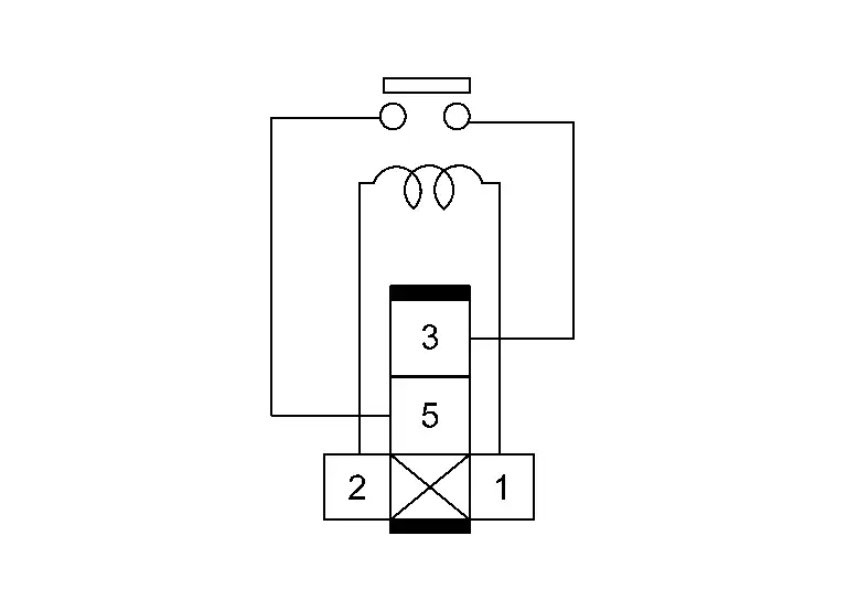
Terminal Condition Continuity 5– 3 When 12 V battery voltage is applied between terminals 1 and 2 Existing When 12 V battery voltage is not applied Non-existing
Is the inspection result normal?
YES>>INSPECTION END
NO>>Replace electric water pump relay.
Electric Water Pump 1 Nissan Ariya 1st generation
Diagnosis Procedure
CHECK ELECTRIC WATER PUMP 1 COMMUNICATION CIRCUIT
Power switch OFF.
Disconnect VCM harness connector and electric water pump 1 harness connector.
Check for continuation between the VCM harness connector and the electric water pump 1 harness connector.
+ − Continuity VCM Electric water pump 1 Connector Terminal Connector Terminal E48 143 F28 2 Existing Also check harness for short to power supply and ground.
Is the inspection result normal?
YES>>GO TO 2.
NO>>Repair or replace error-detected parts.
CHECK FUSE
Remove fuse #94.
Check that the fuse is not blown.
Is the inspection result normal?
YES>>GO TO 3.
NO>>Replace the fuse after repairing the applicable circuit.
CHECK ELECTRIC WATER PUMP 1 POWER SUPPLY
Install the removed fuse.
Reconnect VCM harness connector.
Power switch ON.
Check voltage between the electric water pump 1 harness connector and ground.
+ − Voltage Electric water pump 1 Connector Terminal F28 3 Ground 12 V battery voltage
Is the inspection result normal?
YES>>GO TO 4.
NO>>GO TO 9.
CHECK ELECTRIC WATER PUMP 1 GROUND CIRCUIT
Power switch OFF.
Check for continuation between the electric water pump 1 harness connector and ground.
+ − Continuity Electric water pump 1 Connector Terminal F28 1 Ground Existing
Is the inspection result normal?
YES>>GO TO 5.
NO>>Repair or replace error-detected parts.
CHECK THE HIGH VOLTAGE COOLING SYSTEM FOR LEAKAGE
Check the high voltage cooling system for leakage. Refer to COOLANT : Inspection.
Is the inspection result normal?
YES>>GO TO 6.
NO>>Repair or replace malfunctioning parts.
CHECK OPERATION OF ELECTRIC WATER PUMP
Power switch ON.
Use CONSULT to check "ELECTRIC WATER PUMP 1" for "ACTIVE TEST" on "EV/HEV".
Check electric water pump 1 for operation by changing rotation speed.
Is the inspection result normal?
YES>>GO TO 7.
NO>>Replace electric water pump 1. Refer to ELECTRIC WATER PUMP : Removal & Installation.
CHECK DETECTED DTC
Check DTC related to electric water pump 1.
Is DTC related electric water pump 1 detected?
YES>>GO TO 8.
NO>>INSPECTION END
PERFORM DTC CONFIRMATION PROCEDURE AGAIN
Erace detected DTC.
Perform detected DTC confirmation procedure again.
Use CONSULT to check "Self diagnosis result" for "EV/HEV".
Is DTC related electric water pump 1 detected again?
YES>>Replace electric water pump 1. Refer to ELECTRIC WATER PUMP : Removal & Installation.
NO>>INSPECTION END
CHECK ELECTRIC WATER PUMP 1 POWER SUPPLY CIRCUIT-1
Power switch OFF.
Remove fuse #94.
Check for continuation between fuse #94 and the electric water pump 1 harness connector.
+ − Continuity Electric water pump 1 Connector Terminal Fuse #94 terminal
(Electric water pump 1 side)F28 3 Existing Also check harness for short to power supply and ground.
Is the inspection result normal?
YES>>GO TO 10.
NO>>Repair or replace error-detected parts.
CHECK ELECTRIC WATER PUMP 1 POWER SUPPLY CIRCUIT-2
Remove electric water pump relay.
Check for continuation between fuse #94 and the electric water pump relay harness connector.
+ − Continuity Electric water pump relay Connector Terminal Fuse #94 terminal
(Electric water pump relay side)E129 5 Existing Also check harness for short to power supply and ground.
Is the inspection result normal?
YES>>GO TO 11.
NO>>Repair or replace error-detected parts.
CHECK 12 V BATTERY POWER SUPPLY-1
Check voltage between the electric water pump relay harness connector and ground.
| + | − | Voltage | |
|---|---|---|---|
| Electric water pump relay | |||
| Connector | Terminal | ||
| E129 | 1 | Ground | 12 V battery voltage |
| 3 | |||
Is the inspection result normal?
YES>>GO TO 15.
NO>>GO TO 12.
CHECK FUSIBLE LINK
Remove fusible link #S.
Check that the fusible link is not blown.
Is the inspection result normal?
YES>>GO TO 13.
NO>>Replace the fusible link after repairing the applicable circuit.
CHECK 12 V BATTERY POWER SUPPLY-2
Check voltage between fusible link terminal and ground.
| + | − | Voltage |
|---|---|---|
Fusible link #S (Battery side) |
Ground | 12 V battery voltage |
Is the inspection result normal?
YES>>GO TO 14.
NO>>Check power supply circuit.
CHECK 12 V BATTERY POWER SUPPLY CIRCUIT
Check for continuation between fusible link terminal and the electric water pump relay harness connector.
+ − Continuity Electric water pump relay Connector Terminal Fusible link #S terminal
(Relay side)E129 1 Existing 3 Also check harness for short to power supply and ground.
Is the inspection result normal?
YES>>Perform trouble cause simulation test. Refer to Intermittent Incident.
NO>>Repair or replace error-detected parts.
CHECK ELECTRIC WATER PUMP RELAY
Check electric water pump relay. Refer to Component Inspection.
Is the inspection result normal?
YES>>GO TO 16.
NO>>Replace electric water pump relay.
CHECK ELECTRIC WATER PUMP RELAY CONTROL CIRCUIT
Disconnect VCM harness connector.
Check for continuation between the electric water pump relay harness connector and the VCM harness connector.
+ − Continuity Electric water pump relay VCM Connector Terminal Connector Terminal E129 2 E47 46 Existing Also check harness for short to power supply and ground.
Is the inspection result normal?
YES>>Perform trouble cause simulation test. Refer to Intermittent Incident.
NO>>Repair or replace error-detected parts.
Ev Power Relay Nissan Ariya 2023
Diagnosis Procedure
CHECK 12 V BATTERY POWER SUPPLY-1
Power switch OFF.
Remove EV power relay.
Check voltage between the EV power relay harness connector and ground.
| + | − | Voltage | |
|---|---|---|---|
| EV power relay | |||
| Connector | Terminal | ||
| E139 | 2 | Ground | 12 V battery voltage |
| + | − | Voltage | |
|---|---|---|---|
| EV power relay | |||
| Connector | Terminal | ||
| E138 | 2 | Ground | 12 V battery voltage |
Is the inspection result normal?
YES>>GO TO 5.
NO>>GO TO 2.
CHECK FUSIBLE LINK
Remove fusible link #O.
Check that the fusible link is not blown.
Is the inspection result normal?
YES>>GO TO 3.
NO>>Replace the fusible link after repairing the applicable circuit.
CHECK 12 V BATTERY POWER SUPPLY-2
Check voltage between fusible link terminal and ground.
| + | − | Voltage |
|---|---|---|
Fusible link #O (Battery side) |
Ground | 12 V battery voltage |
Is the inspection result normal?
YES>>GO TO 4.
NO>>Check power supply circuit.
CHECK 12 V BATTERY POWER SUPPLY CIRCUIT
Check for continuation between fusible link terminal and the EV power relay harness connector.
With ProPILOT Assist 2.0 + − Continuity EV power relay Connector Terminal Fusible link #O terminal
(Relay side)E139 2 Existing Without ProPILOT Assist 2.0 + − Continuity EV power relay Connector Terminal Fusible link #O terminal
(Relay side)E138 2 Existing Also check harness for short to power supply and ground.
Is the inspection result normal?
YES>>Perform trouble cause simulation test. Refer to Intermittent Incident.
NO>>Repair or replace error-detected parts.
CHECK EV POWER RELAY
Check EV power relay. Refer to Component Inspection.
Is the inspection result normal?
YES>>GO TO 6.
NO>>Replace EV power relay.
CHECK EV POWER RELAY CONTROL CIRCUIT
Disconnect VCM harness connector.
Check for continuation between the EV power relay harness connector and the VCM harness connector.
With ProPILOT Assist 2.0 + − Continuity EV power relay VCM Connector Terminal Connector Terminal E139 1 E47 46 Existing Without ProPILOT Assist 2.0 + − Continuity EV power relay VCM Connector Terminal Connector Terminal E138 1 E47 46 Existing Also check harness for short to power supply and ground.
Is the inspection result normal?
YES>>GO TO 7.
NO>>Repair or replace error-detected parts.
CHECK VCM GROUND CIRCUIT
Check for continuation between the VCM harness connector and ground.
| + | − | Continuity | |
|---|---|---|---|
| VCM | |||
| Connector | Terminal | ||
| E46 | 28 | Ground | Existing |
| 29 | |||
| 32 | |||
Is the inspection result normal?
YES>>INSPECTION END
NO>>Repair or replace error-detected parts.
Component Inspection
CHECK EV POWER RELAY
Power switch OFF.
Remove EV power relay.
Check the EV power relay under the conditions below.
Terminal Condition Continuity 5 - 3 When 12 V battery voltage is applied between terminals 1 and 2 Existing When 12 V battery voltage is not applied Non-existing
Is the inspection result normal?
YES>>INSPECTION END
NO>>Replace EV power relay.
Evse Connecting Signal Circuit Nissan Ariya: FE0
Diagnosis Procedure
CHECK EVSE CONNECTING SIGNAL CIRCUIT
Power switch OFF.
Disconnect VCM harness connector.
Disconnect On-board charger harness connector.
Check for continuation between the VCM harness connector and the On-board charger harness connector.
+ − Continuity VCM On-board charger Connector Terminal Connector Terminal E47 88 E30 5 Existing Also check harness for short to power supply and ground.
Is the inspection result normal?
YES>>INSPECTION END
NO>>Repair or replace error-detected parts.
High Voltage Junction Box Temperature Sensor Nissan Ariya SUV
Diagnosis Procedure
CHECK HIGH VOLTAGE JUNCTION BOX TEMPERATURE SENSOR
Power switch OFF.
Disconnect high voltage junction box harness connector.
Perform high voltage junction box temperature sensor inspection. Refer to Component Inspection.
Is the inspection result normal?
YES>>GO TO 2.
NO>>Repair or replace error-detected parts.
CHECK HIGH VOLTAGE JUNCTION BOX TEMPERATURE SENSOR CIRCUIT
Disconnect VCM harness connector.
Check for continuation between the high voltage junction box harness connector and the VCM harness connector.
+ − Continuity High voltage junction box VCM Connector Terminal Connector Terminal E1 1 E47 52 Existing 12 68 Also check harness for short to power supply and ground.
Is the inspection result normal?
YES>>INSPECTION END
NO>>Repair or replace error-detected parts.
Component Inspection
CHECK HIGH VOLTAGE JUNCTION BOX TEMPERATURE SENSOR
Power switch OFF.
Disconnect high voltage junction box harness connector.
Check resistance between the high voltage junction box terminals.
High voltage junction box Condition Resistance
(Approx.)+ − Terminal 1 12 Temperature: 0 °C 25 – 31 kΩ Temperature: 25 °C 9 – 11 kΩ
Is the inspection result normal?
YES>>INSPECTION END
NO>>Replace high voltage junction box. Refer to HIGH VOLTAGE JUNCTION BOX : Disassembly & Assembly. (Built-in high voltage junction box temperature sensor)
Immediate Charging Switch Nissan Ariya first Gen
Diagnosis Procedure
CHECK IMMEDIATE CHARGING SWITCH POWER SUPPLY
Power switch OFF.
Disconnect immediate charging switch harness connector.
- Check voltage between the immediate charging switch harness connector and ground.
+ − Voltage Immediate charging switch Connector Terminal M140 1 Ground 12 V battery voltage
Is the inspection result normal?
YES>>GO TO 3.
NO>>GO TO 2.
CHECK IMMEDIATE CHARGING SWITCH SIGNAL CIRCUIT
Disconnect VCM harness connector.
Check for continuation between the immediate charging switch harness connector and the VCM harness connector.
+ − Continuity Immediate charging switch VCM Connector Terminal Connector Terminal M140 1 E46 10 Existing Also check harness for short to power supply and ground.
Is the inspection result normal?
YES>>Perform trouble cause simulation test. Refer to Intermittent Incident.
NO>>Repair or replace error-detected parts.
CHECK IMMEDIATE CHARGING SWITCH GROUND CIRCUIT
Check for continuation between the immediate charging switch harness connector and ground.
| + | − | Continuity | |
|---|---|---|---|
| Immediate charging switch | |||
| Connector | Terminal | ||
| M140 | 2 | Ground | Existing |
Is the inspection result normal?
YES>>GO TO 4.
NO>>Repair or replace error-detected parts.
CHECK IMMEDIATE CHARGING SWITCH
Check immediate charging switch. Refer to Component Inspection.
Is the inspection result normal?
YES>>INSPECTION END
NO>>Replace immediate charging switch. Refer to IMMEDIATE CHARGING SWITCH : Removal & Installation.
Component Inspection
CHECK IMMEDIATE CHARGING SWITCH
Power switch OFF.
Remove immediate charging switch.
Check for continuation between the immediate charging switch terminals under the conditions below.
Terminal Condition Continuity 1 – 2 Immediate charging switch Not pressed Non-existing Pressed Existing
Is the inspection result normal?
YES>>INSPECTION END
NO>>Replace immediate charging switch. Refer to IMMEDIATE CHARGING SWITCH : Removal & Installation.
Insulation Resistance (high Voltage Harness) Nissan Ariya: FE0
Component Inspection
PRECONDITIONING
Disconnect the high voltage circuit. Refer to HOW TO DISCONNECT HIGH VOLTAGE : Precautions.
Check the voltage in the high voltage circuit. Refer to CHECK VOLTAGE IN HIGH VOLTAGE CIRCUIT : Precautions.
GO TO 2.
CHECK HIGH VOLTAGE HARNESS INSULATION RESISTANCE
Check the insulation resistance of the high voltage harnesses using an insulation resistance tester.
Measuring points
With the Nissan Ariya vehicle in an assembled state
Resistance between the harness connector terminals and the body
Harness only
Resistance between the harness connector terminals and the harness connector plastic
Resistance between the harness connector terminals and the harness cover (Shield)
PTC heater
High voltage harness connector Resistance Connector Terminal H2 1 More than 100 MΩ 2 Li-ion battery [To Inverter (front)]
High voltage harness connector Resistance Connector Terminal H5 37 More than 100 MΩ 38 Li-ion battery [To Inverter (rear)]
High voltage harness connector Resistance Connector Terminal H7 40 More than 100 MΩ 41 Inverter (front) (To high voltage junction box)
High voltage harness connector Resistance Connector Terminal H12 N More than 100 MΩ P Electric compressor
High voltage harness connector Resistance Connector Terminal H9 7 More than 100 MΩ 8 Inverter (front) (To Li-ion battery)
High voltage harness connector Resistance Connector Terminal H6 N More than 100 MΩ P High voltage junction box (To PTC heater)
High voltage harness connector Resistance Connector Terminal H1 13 More than 100 MΩ 14 High voltage junction box (To inverter (front))
High voltage harness connector Resistance Connector Terminal H10 N More than 100 MΩ P High voltage junction box (To electric compressor)
High voltage harness connector Resistance Connector Terminal H11 18 More than 100 MΩ 19 Inverter (rear)
High voltage harness connector Resistance Connector Terminal H8 N More than 100 MΩ P
Is the inspection result normal?
YES>>INSPECTION END
NO>>Replace error-detected high voltage harness.
Pre-Charge Relay Circuit Nissan Ariya 2023
Diagnosis Procedure
CHECK PRE-CHARGE RELAY GROUND CIRCUIT
Power switch OFF.
Disconnect Li-ion battery harness connector.
Disconnect VCM harness connector.
Check for continuation between the Li-ion battery harness connector and the VCM harness connector.
Li-ion battery VCM Continuity Connector Terminal Connector Terminal E9 14 E47 72 Existing
Is the inspection result normal?
YES>>INSPECTION END
NO>>Repair or replace error-detected parts.
Quick Charge Relay Circuit Nissan Ariya 1st generation
Diagnosis Procedure
CHECK QUICK CHARGE RELAY GROUND CIRCUIT
Power switch OFF.
Disconnect Li-ion battery harness connector.
Disconnect VCM harness connector.
Check for continuation between the Li-ion battery harness connector and the VCM harness connector.
QUICK CHARGE RELAY-1 Li-ion battery VCM Continuity Connector Terminal Connector Terminal E9 2 E47 91 Existing QUICK CHARGE RELAY-2 Li-ion battery VCM Continuity Connector Terminal Connector Terminal E9 8 E47 92 Existing
Is the inspection result normal?
YES>>GO TO 2.
NO>>Repair or replace error-detected parts.
CHECK QUICK CHARGE RELAY STATE SIGNAL CIRCUIT
Check for continuation between the Li-ion battery harness connector and the VCM harness connector.
| Li-ion battery | VCM | Continuity | ||
|---|---|---|---|---|
| Connector | Terminal | Connector | Terminal | |
| E9 | 25 | E48 | 122 | Existing |
Is the inspection result normal?
YES>>GO TO 3.
NO>>Repair or replace error-detected parts.
PRECONDITIONING
Disconnect the high voltage circuit. Refer to HOW TO DISCONNECT HIGH VOLTAGE : Precautions.
Check the voltage in the high voltage circuit. Refer to CHECK VOLTAGE IN HIGH VOLTAGE CIRCUIT : Precautions.
Remove the Li-ion battery from the Nissan Ariya vehicle. Refer to Removal & Installation(66kWh LI-ION BATTERY 2WD models), Removal & Installation(66kWh LI-ION BATTERY AWD models), Removal & Installation(91kWh LI-ION BATTERY 2WD models), Removal & Installation(91kWh LI-ION BATTERY AWD models).
Remove battery pack upper case. Refer to Removal & Installation(66kWh LI-ION BATTERY), Removal & Installation(91kWh LI-ION BATTERY).
GO TO 4.
CHECK CONNECTOR CONNECTION CONDITION
Check the LBC and each of the junction box harness connectors connection conditions.
Is the inspection result normal?
YES>>GO TO 5.
NO>>Restore the connection condition.
CHECK FOR CONTINUATION BETWEEN THE HIGH VOLTAGE JUNCTION BOX AND THE Nissan Ariya Vehicle COMMUNICATION CONNECTOR
Disconnect high voltage junction box harness connector.
Check for continuation between the high voltage junction box harness connector and the Nissan Ariya vehicle communication harness connector. Refer to Circuit Diagram(66kWh LI-ION BATTERY), Circuit Diagram(91kWh LI-ION BATTERY).
High voltage junction box Nissan Ariya Vehicle communication connector Continuity Connector Terminal Connector Terminal LB11 S6 LB2 2 Existing S8 8 Also check harness for short to ground and short between harnesses.
Is the inspection result normal?
YES>>INSPECTION END
NO>>Repair or replace the Li-ion battery Nissan Ariya vehicle communication harness.
Refrigerant Pressure Sensor Nissan Ariya
Diagnosis Procedure
CHECK REFRIGERANT PRESSURE SENSOR POWER SUPPLY-1
Power switch OFF.
Disconnect refrigerant pressure sensor harness connector.
Power switch ON.
Check voltage between the refrigerant pressure sensor harness connector terminals.
Refrigerant pressure sensor Voltage
(Approx.)Connector + − Terminal B184 3 1 5 V
Is the inspection result normal?
YES>>GO TO 6.
NO>>GO TO 2.
CHECK REFRIGERANT PRESSURE SENSOR POWER SUPPLY-2
Check voltage between the refrigerant pressure harness connector and ground.
| + | − | Voltage (Approx.) | |
|---|---|---|---|
| Refrigerant pressure sensor | |||
| Connector | Terminal | ||
| B184 | 3 | Ground | 5 V |
Is the inspection result normal?
YES>>GO TO 4.
NO>>GO TO 3.
CHECK REFRIGERANT PRESSURE SENSOR POWER SUPPLY CIRCUIT
Power switch OFF.
Disconnect VCM harness connector.
Check for continuation between the refrigerant pressure sensor harness connector and the VCM harness connector.
+ − Continuity Refrigerant pressure sensor VCM Connector Terminal Connector Terminal B184 3 E48 145 Existing Also check harness for short to power supply and ground.
Is the inspection result normal?
YES>>Perform VCM power supply and ground inspection. Refer to Diagnosis Procedure.
NO>>Repair or replace error-detected parts.
CHECK REFRIGERANT PRESSURE SENSOR GROUND CIRCUIT
Power switch OFF.
Disconnect VCM harness connector.
Check for continuation between the refrigerant pressure sensor harness connector and the VCM harness connector.
+ − Continuity Refrigerant pressure sensor VCM Connector Terminal Connector Terminal B184 1 E48 134 Existing Also check harness for short to power supply and ground.
Is the inspection result normal?
YES>>GO TO 5.
NO>>Repair or replace error-detected parts.
CHECK VCM GROUND CIRCUIT
Check for continuation between the VCM harness connector and ground.
| + | − | Continuity | |
|---|---|---|---|
| VCM | |||
| Connector | Terminal | ||
| E46 | 28 | Ground | Existing |
| 29 | |||
| 32 | |||
Is the inspection result normal?
YES>>INSPECTION END
NO>>Repair or replace error-detected parts.
CHECK REFRIGERANT PRESSURE SENSOR SIGNAL CIRCUIT
Power switch OFF.
Disconnect VCM harness connector.
Check for continuation between the refrigerant pressure sensor harness connector and the VCM harness connector.
+ − Continuity Refrigerant pressure sensor VCM Connector Terminal Connector Terminal B184 2 E48 133 Existing Also check harness for short to power supply and ground.
Is the inspection result normal?
YES>>Replace refrigerant pressure sensor. Refer to Removal & Installation.
NO>>Repair or replace error-detected parts.
Stop Lamp Switch Nissan Ariya SUV
Diagnosis Procedure
CHECK STOP LAMP SWITCH INPUT SIGNAL
Power switch OFF.
Disconnect VCM harness connector.
Power switch ON.
Check voltage between the VCM harness connector and ground.
+ − Voltage VCM Connector Terminal E46 20 Ground 12 V battery voltage
Is the inspection result normal?
YES>>Perform trouble cause simulation test. Refer to Intermittent Incident.
NO>>GO TO 2.
CHECK STOP LAMP SWITCH POWER SUPPLY
Disconnect stop lamp switch harness connector.
Check voltage between the stop lamp switch harness connector and ground.
+ − Voltage Stop lamp switch Connector Terminal E115 4 Ground 12 V battery voltage
Is the inspection result normal?
YES>>GO TO 5.
NO>>GO TO 3.
CHECK FUSE
Power switch OFF.
Remove fuse #39.
Check that the fuse is not blown.
Is the inspection result normal?
YES>>GO TO 4.
NO>>Replace the fuse after repairing the applicable circuit.
CHECK STOP LAMP SWITCH POWER SUPPLY CIRCUIT
Check for continuation between fuse #39 terminal and the stop lamp switch harness connector.
+ − Continuity Stop lamp switch Connector Terminal Fuse #39 terminal
(Stop lamp switch side)E115 4 Existing Also check harness for short to power supply and ground.
Is the inspection result normal?
YES>>Check power supply circuit.
NO>>Repair or replace error-detected parts.
CHECK STOP LAMP SWITCH SIGNAL CIRCUIT
Check for continuation between the stop lamp switch harness connector and the VCM harness connector.
+ − Continuity Stop lamp switch VCM Connector Terminal Connector Terminal E115 3 E46 20 Existing Also check harness for short to power supply and ground.
Is the inspection result normal?
YES>>GO TO 6.
NO>>Repair or replace error-detected parts.
CHECK STOP LAMP SWITCH
Check stop lamp switch. Refer to Component Inspection.
Is the inspection result normal?
YES>>Perform trouble cause simulation test. Refer to Intermittent Incident.
NO>>Adjust or replace stop lamp switch.
Component Inspection
CHECK STOP LAMP SWITCH-1
Power switch OFF.
Disconnect stop lamp switch harness connector.
Check for continuation between the stop lamp switch terminals under the conditions below.
Terminal Condition Continuity 3 and 4 Brake pedal Depressed Non-existing Fully released Existing
Is the inspection result normal?
YES>>INSPECTION END
NO>>GO TO 2.
CHECK STOP LAMP SWITCH-2
Adjust stop lamp switch. Refer to BRAKE PEDAL : Periodic Maintenance Operation.
Check for continuation between the stop lamp switch terminals under the conditions below.
Terminal Condition Continuity 3 and 4 Brake pedal Depressed Non-existing Fully released Existing
Is the inspection result normal?
YES>>INSPECTION END
NO>>Replace stop lamp switch. Refer to BRAKE PEDAL : Removal & Installation.
Traction Motor Oil Pump Relay Nissan Ariya
Diagnosis Procedure
CHECK FUSE
Power switch OFF.
Remove fuse #90.
Check that the fuse is not blown.
Is the inspection result normal?
YES>>GO TO 2.
NO>>Replace the fuse after repairing the applicable circuit.
CHECK FUSIBLE LINK
Remove fusible link #P.
Check that the fusible link is not blown.
Is the inspection result normal?
YES>>GO TO 3.
NO>>Replace the fusible link after repairing the applicable circuit.
CHECK TRACTION MOTOR OIL PUMP RELAY CONTROL SIGNAL POWER SUPPLY
Install the removed fuse and the fusible link.
Remove traction motor oil pump relay.
Power switch ON.
Check voltage between the traction motor oil pump relay harness connector and ground.
+ − Voltage Traction motor oil pump relay Connector Terminal E128 2 Ground 12 V battery voltage
Is the inspection result normal?
YES>>GO TO 4.
NO>>GO TO 7.
CHECK TRACTION MOTOR OIL PUMP RELAY POWER SUPPLY
Check voltage between the traction motor oil pump relay harness connector and ground.
+ − Voltage Traction motor oil pump relay Connector Terminal E128 3 Ground 12 V battery voltage
Is the inspection result normal?
YES>>GO TO 5.
NO>>GO TO 8.
CHECK TRACTION MOTOR OIL PUMP RELAY CONTROL SIGNAL CIRCUIT
Power switch OFF.
Disconnect VCM harness connector.
Check for continuation between the traction motor oil pump relay harness connector and the VCM harness connector.
+ − Continuity Traction motor oil pump relay VCM Connector Terminal Connector Terminal E128 1 E48 97 Existing Also check harness for short to power supply and ground.
Is the inspection result normal?
YES>>GO TO 6.
NO>>Repair or replace error-detected parts.
CHECK TRACTION MOTOR OIL PUMP RELAY
Check traction motor oil pump relay. Refer to Component Inspection.
Is the inspection result normal?
YES>>Perform trouble cause simulation test. Refer to Intermittent Incident.
NO>>Repair or replace error-detected parts.
CHECK TRACTION MOTOR OIL PUMP RELAY CONTROL SIGNAL POWER SUPPLY CIRCUIT
Power switch OFF.
Check for continuation between the traction motor oil pump relay harness connector and fuse #90 terminal.
+ − Continuity Traction motor oil pump relay Connector Terminal Fuse #90 terminal E128 2 Existing
Is the inspection result normal?
YES>>Perform trouble cause simulation test. Refer to Intermittent Incident.
NO>>Repair or replace error-detected parts.
CHECK TRACTION MOTOR OIL PUMP RELAY POWER SUPPLY CIRCUIT
Power switch OFF.
Check for continuation between the traction motor oil pump relay harness connector and fusible link terminal.
+ − Continuity Traction motor oil pump relay Connector Terminal Fusible link #P terminal E128 3 Existing
Is the inspection result normal?
YES>>Perform trouble cause simulation test. Refer to Intermittent Incident.
NO>>Repair or replace error-detected parts.
Component Inspection
CHECK TRACTION MOTOR OIL PUMP RELAY
Power switch OFF.
Remove traction motor oil pump relay. Refer to Component Parts Location.
Check the traction motor oil pump relay under the conditions below.
Traction motor oil pump relay Condition Continuity Terminal 3 5 When 12 V battery voltage is applied between terminals 1 and 2 Existing When 12 V battery voltage is not applied Non-existing
Is the inspection result normal?
YES>>INSPECTION END
NO>>Replace traction motor oil pump relay.
Quick Charger Port Temperature Sensor Circuit Nissan Ariya SUV
Diagnosis Procedure
CHECK CHARGE PORT
Power switch OFF.
Disconnect charge port Nissan Ariya vehicle side harness connector.
Check the charge port. Refer to Component Inspection.
Is the inspection result normal?
YES>>GO TO 2.
NO>>Replace charge port. Refer to CHARGE PORT : Removal & Installation.
CHECK QUICK CHARGE PORT TEMPERATURE SENSOR CIRCUIT CONTINUITY
Disconnect VCM Nissan Ariya vehicle side harness connector.
Check for continuation between the VCM vehicle harness connector and the charge port Nissan Ariya vehicle side harness connector.
Charge port VCM Continuity Connector Terminal Connector Terminal E27 18 E48 135 Existing 19 124 Also check harness for short to ground and short between harnesses.
Is the inspection result normal?
YES>>GO TO 3
NO>>Repair or replace error-detected parts.
CHECK QUICK CHARGE PORT TEMPERATURE SENSOR GROUND CIRCUIT
Check for continuation between the charge port Nissan Ariya vehicle side harness connector and the VCM vehicle side harness connector.
| Charge port | VCM | Continuity | ||
|---|---|---|---|---|
| Connector | Terminal | Connector | Terminal | |
| E27 | 20 | E48 | 140 | Existing |
Is the inspection result normal?
YES>>GO TO 4
NO>>Repair or replace error-detected parts.
TROUBLE CAUSE SIMULATION TEST
Perform trouble cause simulation test. Refer to Intermittent Incident.
Is the inspection result normal?
YES>>INSPECTION END
NO>>Repair or replace error-detected parts.